Catalog mikro mikro din310-dienhathe.vn
•
0 gefällt mir•32 views

Xem thêm tại website : http://tailieukythuat.info

Empfohlen
Empfohlen
Weitere ähnliche Inhalte
Was ist angesagt?
Was ist angesagt? (12)
Ähnlich wie Catalog mikro mikro din310-dienhathe.vn
Ähnlich wie Catalog mikro mikro din310-dienhathe.vn (20)
Mehr von Dien Ha The
Mehr von Dien Ha The (20)
Kürzlich hochgeladen
Kürzlich hochgeladen (20)
Catalog mikro mikro din310-dienhathe.vn
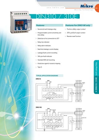
- 1. TRIP CONTACT LOAD L1 L2 L3 N 62 3 4 5 71 8 9 COM NO NC 10 11 12 13 14 L N AUX SHUNT TRIP MIKRO ZCT DIN310 Features • Numerical earth leakage relay • Programmable current sensitivity and time delay • Detection of no connection to ZCT • Relay trip indicator • Relay alarm indicator • Real-time leakage current display • Leakage fault current recording • 50% pre-fault indicator • Standard DIN rail mounting • Protection against nuisance tripping • Type A TYPICAL APPLICATION DIAGRAMS Features For DIN310E only • Positive safety output contact • 50% pre-fault output contact • Remote reset function DIN310 / 310E EarthLeakageRelayDIN310/310E TRIP CONTACT SAFETY CONTACT LOAD L1 L2 L3 N 62 3 4 5 71 8 9 10 11 12 13 14 L N AUX CONTACTOR MIKRO ZCT DIN310E REMOTE RESET ALARM CONTACT NO NC NCCOM COM NO DIN310 DIN310E
- 2. Technical Data AUXILIARY SUPPLY DIN310-240 A(6) : 204 ~ 265V AC DIN310E-240 A(6) : 204 ~ 265V AC Rated frequency : 50 or 60 Hz VA rating : 3VA typical SETTING RANGES Sensitivity adjustment : 30 mA, 50 mA, 0.10 A –1.00 A (Step = 50 mA), 1.00 A – 10.0 A (Step = 1.00 A) Time delay adjustment : Instantaneous, 0.1s – 3.0s. Step = 0.10 sec. CONTACTS Contact arrangement : Change-over Contact rating : 5 A, 250V AC ( cosj = 1 ) Contact material : Silver alloy Expected electrical life : 100,000 operations at rated current Expected mechanical life : 5 x 10⁶ operations RECORD Fault record : 3 latest tripped fault currents Storage : Non-volatile memory INPUT Remote reset* : N.O. dry contact OUTPUTS Trip Contact : Activated if relay tripped or ZCT fault Positive safety contact* : Activated when ZCT is connected properly to the relay Pre-fault alarm contact* : Activated when leakage current exceeded 50% of sensitivity setting INDICATORS 50% pre-fault alarm : Red indicator Time delay : Red indicator Leakage trip : 7-segment display and red indicator ZCT fault : 7-segment display and red indicator Real time leakage current : 7-segment display ZERO-PHASE CURRENT TRANSFORMER To operate with Mikro’s ZCT series of current transformer MECHANICAL Mounting method : Standard 35 mm DIN rail mounting Approximate weight : 0.38 kg (Excluding ZCT) ENVIRONMENTALCONDITIONS Temperature : -5˚C to +55˚C Humidity : 56 days at 93% RH and 40˚C non-condensing * Applicable to DIN310E series only Ordering Information Front Side 71 mm 20mm 45mm 20mm 70 mm 85mm 30mm 20mm20mm CASEDIMENSIONS EarthLeakageRelayDIN310/310E DIN310 - 240 A For 50 Hz system, auxiliary voltage 240 V AC DIN310E - 240 A For 50 Hz system, auxiliary voltage 240 V AC DIN310 - 240 A6 For 60 Hz system, auxiliary voltage 240 V AC DIN310E - 240 A6 For 60 Hz system, auxiliary voltage 240 V AC MODEL DESCRIPTION