SlideShare ist ein Scribd-Unternehmen logo
1 von 73
1. Introduction
There has been a rapid growth in servers within data centers driven by growth of
enterprises since the late nineties. The servers are commonly used for running business-critical
applications such as enterprise resource planning, database, customer relationship management,
and e-commerce applications. Because these servers and applications involve high labor cost in
maintenance, upgrades, and operation, there is a significant interest in reducing the number of
servers necessary for the applications.
This strategy is supported by the fact that many servers in enterprise data centers are
under-utilized most of the time, with a typical average utilization below 30%. On the other hand,
some servers in a data center may also become overloaded under peak demands, resulting in lower
application throughput and longer latency.
Server consolidation has become a common practice in enterprise data centers because of
the need to cut cost and increase return on IT investment. Many enterprise applications that
traditionally ran on dedicated servers are consolidated onto a smaller and shared pool of servers.
Although server consolidation offers great potential to increase resource utilization and improve
application performance, it may also introduce new complexity in managing the consolidated
servers. This has given rise to a re-surging interest in virtualization technology.
There are two main types of virtualization technologies today — hypervisor-based
technology including VMware , Microsoft Virtual Server , OVirt and Xen; and operating system
(OS) level virtualization including OpenVZ , Linux VServer , and Solaris Zones . These
technologies allow a single physical server to be partitioned into multiple isolated virtual
containers for running multiple applications at the same time. This enables easier centralized
server administration and higher operational efficiency.
Page 1
However, capacity management for the virtual containers is not a trivial task for system
administrators. One reason is that enterprise applications often have resource demands that vary
over time and may shift from one tier to another in a multi-tiered system. Figures 1(a) and 1(b)
show the CPU consumptions of two servers in an enterprise data center for a week. Both have a
high peak-tomean ratio in their resource usage, and their peaks are not synchronized. This means
if the two servers were to be consolidated into two virtual containers on a shared server; the
resources may be dynamically allocated to the two containers such that both of the hosted
applications could meet their quality-of-service (QoS) goals while utilizing server resources more
efficiently. An adaptive CPU resource controller was described in to achieve this goal. Similar
algorithms were developed for dynamic memory management in VMware ESX server . There is
another important issue that is worth considering in terms of capacity management.
As we can see, the peak consumption is at about 3.8 CPUs. However, it does not
necessarily imply that a total of 3.8 CPUs are sufficient to run the two virtual containers after
consolidation due to potential virtualization overhead.
In this project, we focus on two representative virtualization technologies, Xen from
hypervisor-based virtualization (OVirt) and based on the Linux operating system. We use
different application as an example of a multi-tiered application and evaluate its performance in
the context of server consolidation using these two virtualization technologies. In particular, we
present the results of our experiments that answer the following questions, and compare the
answers to each question between OVirt and Xen.
• How is application-level performance, including throughput and response time, impacted
compared to its performance on a base Linux system?
• As workload increases, how does application-level performance scale up and what is the impact
on server resource consumption?
• How is application-level performance affected when multiple tiers of each application are placed
on virtualized servers in different ways?
• As the number of multi-tiered applications increases, how do application-level performance and
resource consumption scale?
• In each scenario, what are the values of some critical underlying system metrics and what do
they tell us about plausible causes of the observed virtualization overhead?
Page 2
1.1 Definition of Cloud Computing
Cloud computing is a model for enabling convenient, on-demand network access to a
shared pool of configurable computing resources (e.g., networks, servers, storage, applications and
services) that can be rapidly provisioned and released with minimal management effort on service
provider interaction.
1.2 History of Cloud Computing
With the advent of mini computers and later personal computers in the 1970’s, we saw the
ability to utilize the benefits of technology rolled out to a much broader audience. While still
relatively expensive and functionally basic machines – the personal computer put computing onto
my desktop in a reasonably well-resourced organization.
The advent of the internet changed things forever, both from the perspective of the network
and perspective of individual computers. The increased reliability and reduced cost of the internet
along with the decreasing cost of computers, led to increased use of web based applications. This
along with the demand for application access via multiple devices using multiple form factors led
to a rapid growth in the Cloud Computing at an infrastructure, a platform and an application level.
In these earliest stages, the term “cloud” was used to represent the computing space between the
provider and the end user. During the second half of the 1990s, companies began to gain a better
understanding of cloud computing and its usefulness in providing superior solutions and services
to customers while drastically improving internal efficiencies. Meanwhile, Google had become a
key player in the Internet commerce marketplace. In 2006 the company launched its Google Docs
services, which brought the power of cloud computing and document sharing directly to end users.
From 2008 to till date we have different cloud providers with flavors of Cloud Computing. We can
mention Microsoft Hyper-V, VMWare, Openstack, Ganeti as example.
1.3 Cloud Computing Benefits
Flexibility – Scale up and down to meet your organization’s requirements. In today’s economy,
this flexibility is key. One can adjust his IT expenditures to meet your organization’s immediate
needs. He no longer have to build for the future, or be constrained by decisions made or contracts
signed in the past.
Security – Rest assured that your data in the cloud is much more secure than what lives on a tower
under our desk or in your small unsecured server room.
Capacity – In the past, you had to spend a lot of your IT budget on human resources to manage
your software. With cloud computing, that’s no longer an issue. Now, you can focus on how the
solution will help you further your mission. The IT piece belongs to somebody else.
Cost – Using cloud technology reduces your maintenance fees. No more servers, software, and
update fees. Many of the hidden costs typically associated with software implementation,
customization, hardware, maintenance, and training are rolled into a transparent subscription fee.
Page 3
It’s open – Internet standards and web services allow you to connect services to each other. This
means that you can centralize your information and access it from anywhere in the world, on any
computer or mobile device, at any time.
1.4 Classification based upon service provided
There are three basic kinds of cloud service models. Each share similarities but have their
own distinct differences as well. These service models are Infrastructure-as-a-Service, Software-
as-a-Service and Platform-as-a-Service. It helps to think of these services in layers.
Infrastructure-as-a-Service (IaaS)
Infrastructure-as-a-Service is the first layer and foundation of cloud computing. Using this
service model, you manage your applications, data, operating system, middleware and runtime.
The service provider manages your virtualization, servers, networking and storage. This allows
you to avoid expenditure on hardware and human capital; reduce your ROI risk; and streamline
and automate scaling. According to a 2011 article released by Venture Beat. Some of the biggest
names in IaaS include Amazon, Microsoft, VMWare, Rackspace and Red Hat.
An example of a typical need for this model is someone who needs extra data space for
processing power on occasion. Infrastructure-as-a-Service allows you to easily scale based on your
needs and you only pay for the resources used. This means that the extra data processing space is
available to you whenever you need it, and when you don’t you are not paying for it, saving you
money and providing your business exactly what it needs.
Platform-as-a-Service (PaaS)
This cloud service model could be considered the second layer. You manage your
applications and data and the cloud vendor manages everything else. Benefits for using Platform-
as-a-Service include streamlined version deployment and the ability to change or upgrade and
minimize expenses. One popular Platform-as-a-Service is the Google app engine.
A business with limited resources interested in app testing or development might find
Platform-as-a-Service beneficial to eliminate costs of upkeep for hardware. In this model, your
business benefits because it is not necessary to hire people to maintain these systems. A scalable
processing center is available at your disposal to use as you need (again, you only pay for what
you use).
Page 4
Figure 1.2: Cloud Services
Software-as-a-Service (SaaS)
This is the final layer of the cloud services model. This allows your business to run
programs in the cloud where all portions are managed by the cloud vendor. Your users will have
assured compatibility and easier collaboration because all will be using the same software. Your
company won’t need to pay extra licensing fees and you can easily add new users. As consumers
we interact with Software-as-a-Service based applications every day without even realizing it.
Examples of this are online banking and email such as Gmail and Hotmail.
If you have a team that is able to maintain your hardware, but you want to make it easier to
streamline your software programs for ease of use and compatibility, Software-as-a-Service will
best suit your needs. Larger companies are a good example to use in this scenario. Teams of large
people need to be able to work collaboratively in order to achieve your company’s goals. By using
Software-as-a-Service your team will be able to access the software from a variety of devices, in
the office or on the go, which allows easier collaboration among your team.
As you can see, cloud computing isn’t always cut and dry. While there are similarities
among the three cloud service models, there are significant differences as well. It is up to the
consumer to choose which model is best for their company in order to use this invaluable service
to its fullest potential.
Page 5
2. Virtualization
Virtualization can be applied very broadly to just about everything you can imagine
including memory, networks, storage, hardware, operating systems, and applications.
Virtualization has three characteristics that make it ideal for cloud computing:
Partitioning: In virtualization, you can use partitioning to support many applications and
operating systems (OSes) in a single physical system.
Isolation: Because each virtual machine is isolated, each machine is protected from
crashes and viruses in the other machines. What makes virtualization so important for the cloud is
that it decouples the software from the hardware.
Encapsulation: Encapsulation can protect each application so that it doesn’t interfere with
other applications. Using encapsulation, a virtual machine can be represented (and even stored) as
a single file, making it easy to identify and present to other applications.
To understand how virtualization helps with cloud computing, we must understand its
many forms. In essence, in all cases, a resource actually emulates or imitates another resource.
Here are some examples:
Virtual memory: Disks have a lot more space than memory. PCs can use virtual memory
to borrow extra memory from the hard disk. Although virtual disks are slower than real memory,
if managed right, the substitution works surprisingly well.
Software: There is virtualization software available that can emulate an entire computer,
which means 1 computer can perform as though it were actually 20 computers. Using this kind of
software you might be able to move from a data center with thousands of servers to one that
supports as few as a couple of hundred.
To manage the various aspects of virtualization in cloud computing most companies use
hypervisors. Because in cloud computing you need to support many different operating
environments, the hypervisor becomes an ideal delivery mechanism by allowing you to show the
same application on lots of different systems. Because hypervisors can load multiple operating
systems, they are a very practical way of getting things virtualized quickly and efficiently. Let’s
try to draw a picture on above statement.
Page 6
Figure 1.3: A normal Workstation / Computer
Page 7
Figure 1.4: A Workstation using Hypervisor on it
2.1 Hypervisor
The evolution of virtualization greatly revolves around one piece of very important software. This
is the hypervisor. As an integral component, this software piece allows for physical devices to
share their resources amongst virtual machines running as guests on to top of that physical
hardware. To further clarify the technology, it’s important to analyze a few key definitions:
Type I Hypervisor: This type of hypervisor (pictured at the beginning of the article) is
deployed as a bare-metal installation. This means that the first thing to be installed on a server as
the operating system will be the hypervisor. The benefit of this software is that the hypervisor will
communicate directly with the underlying physical server hardware. Those resources are then
paravirtualized and delivered to the running VMs. This is the preferred method for many
production systems. Modern equivalents of type I hypervisor include Oracle VM Server for
SPARC, Oracle VM Server for x86, the Citrix XenServer, VMware ESX/ESXi and Microsoft
Hyper-V 2008/2012. Linux's Kernel-based Virtual Machine (KVM) and FreeBSD's behave are
kernel modules that effectively convert the host operating system to a type-1 hypervisor.
Page 8
Figure 2.1: Type1 Hypervisor
Type II Hypervisor: This model (shown below) is also known as a hosted hypervisor. The
software is not installed onto the bare-metal, but instead is loaded on top of an already live
operating system. For example, a server running Windows Server 2008R2 can have VMware
Workstation 8 installed on top of that OS. Although there is an extra hop for the resources to take
when they pass through to the VM – the latency is minimal and with today’s modern software
enhancements, the hypervisor can still perform optimally. VMware Workstation, VMware Player,
VirtualBox and QEMU are examples of type-2 hypervisors.
Figure 1.6: Type2 Hypervisor
Guest Machine / VM: A guest machine, also known as a virtual machine (VM) is the
workload installed on top of the hypervisor. This can be a virtual appliance, operating system or
other type of virtualization-ready workload. This guest machine will, for all intents and purposes,
believe that it is its own unit with its own dedicated resources. So, instead of using a physical
server for just one purpose, virtualization allows for multiple VMs to run on top of that physical
host. All of this happens while resources are intelligently shared between other VMs.
Page 9
Host Machine: This is known as the physical host. Within virtualization, there may be
several components – SAN, LAN, wiring, and so on. In this case, we are focusing on the resources
located on the physical server. The resource can include RAM and CPU. These are then divided
between VMs and distributed as the administrator sees fit. So, a machine needing more RAM (a
domain controller) would receive that allocation, while a less important VM (a licensing server for
example) would have fewer resources. With today’s hypervisor technologies, many of these
resources can be dynamically allocated.
2.2 Introduction of Ganeti - Google Code
Ganeti is a virtual machine cluster management tool developed by Google. This virtual
server management software tool built on top of existing virtualization technologies such as Xen
or KVM and LVM for disk management, and optionally DRBD for disk replication across
physical hosts.
Ganeti is essentially a wrapper around existing hypervisors which makes it convenient for
system administrators to set up a cluster. It is used by Google for its Internal Computing
Infrastructure and also used by the former Open Source Development Labs (now Linux
Foundation) for hosting open source projects.
Ganeti requires pre-installed virtualization software on your servers in order to function. Once
installed, the tool assumes management of the virtual instances. Ganeti controls:
• Disk creation management
• Operating system installation for instances
• Startup, shutdown, and failover between physical systems
Ganeti is designed to facilitate cluster management of virtual servers and to provide fast and
simple recovery after physical failures using commodity hardware.
Roman Marxer, A Ganeti developer from Google says:
"Ganeti started as a small project in Google's Zurich office. We've been using it internally for a
while, and now we're excited to share it more broadly under GPLv2.
Here at Google, we've used Ganeti in the internal corporate environment to facilitate cluster
management of virtual servers in commodity hardware, increasing the efficiency of hardware
usage and saving space, power and cooling. Ganeti also provides fast and simple recovery after
physical failures."
2.3 Ganeti Pros and Cons
Ganeti supports a very lightweight architecture which is very useful to start with a commodity
hardware. From starting a single node installation an administrator can scale out the cluster very
easily. It is designed to use local storage also compatible with larger storage solutions. It has fault-
tolerance as a built-in feature. In a word it is very simple to manage and maintain.
Ganeti is admin centric clustering solution which is the main barrier for public cloud deployment.
Page 10
2.4 Some necessary tools to work with Ganeti
2.4.1 KVM Hypervisor
Kernel-based Virtual Machine (KVM) is a virtualization infrastructure for the Linux kernel
that turns it into a hypervisor. It was merged into the Linux kernel mainline in kernel version
2.6.20, which was released on February 5, 2007. KVM requires a processor with hardware
virtualization extension. KVM has also been ported to FreeBSD and illumos in the form of
loadable kernel modules. A wide variety of guest operating systems work with KVM, including
many flavors and versions of Linux, BSD, Solaris, Windows, Haiku, ReactOS, Plan 9, AROS
Research Operating System and OS X.
Analysis shows that KVM can be 60-90% less expensive than other solutions, while
offering the same core functionality. KVM represents a truly open solution that delivers real value
in terms of functionality. Organizations save on licensing costs while enjoying the technical and
financial advantages of an open multi-vendor ecosystem.
Linux includes C-Groups (control groups), which allow fine-grained QoS policies for
Linux processes. Because KVM is part of the Linux kernel, a VM is no different than any other
program running on Linux. So administrators can set defined thresholds for CPU, memory,
network, and disk I/O, guaranteeing the QoS for given VMs.
2.4.2 LVM
In Linux, Logical Volume Manager (LVM) is a device mapper target that provides logical
volume management for the Linux kernel. Most modern Linux distributions are LVM-aware to the
point of being able to have their root file systems on a logical volume.
Basic functionality
• Volume groups (VGs) can be resized online by absorbing new physical volumes (PVs) or
ejecting existing ones.
• Logical volumes (LVs) can be resized online by concatenating extents onto them or
truncating extents from them.
• LVs can be moved between PVs.
• Creation of read-only snapshots of logical volumes (LVM1), or read-write snapshots
(LVM2).
Basic building blocks of LVM:
Physical volume (PV): Partition on hard disk (or even the disk itself or loopback file) on which
you can have volume groups. It has a special header and is divided into physical extents. Think of
physical volumes as big building blocks used to build your hard drive.
Page 11
Volume group (VG): Group of physical volumes used as a storage volume (as one disk). They
contain logical volumes. Think of volume groups as hard drives.
Logical volume (LV): A "virtual/logical partition" that resides in a volume group and is composed
of physical extents. Think of logical volumes as normal partitions.
Physical extent (PE): The smallest size in the physical volume that can be assigned to a logical
volume (default 4MiB). Think of physical extents as parts of disks that can be allocated to any
partition.
Figure 1.7: LVM
Common uses
LVM is commonly used for the following purposes:
• Managing large hard disk farms by allowing disks to be added and replaced without
downtime or service disruption, in combination with hot swapping.
• On small systems (like a desktop at home), instead of having to estimate at installation
time how big a partition might need to be in the future, LVM allows file systems to be
easily resized later as needed.
• Performing consistent backups by taking snapshots of the logical volumes.
• Creating single logical volumes of multiple physical volumes or entire hard disks
(somewhat similar to RAID 0, but more similar to JBOD), allowing for dynamic volume
resizing.
• LVM can be considered as a thin software layer on top of the hard disks and partitions,
which creates an abstraction of continuity and ease-of-use for managing hard drive
replacement, re-partitioning, and backup.
2.4.3 DRBD
Page 12
DRBD software is a distributed replicated storage system for the Linux platform. It is
implemented as several userspace management applications and some shell scripts and is normally
used on high availability (HA) computer clusters.
DRBD also refers to the logical block devices provided by the scheme and to the software that
implements it. DRBD device and DRBD block device are also often used for the former. The
DRBD software is free software released under the terms of the GNU General Public License
version 2.
DRBD layers logical block devices over existing local block devices on participating cluster
nodes. Writes to the primary node are transferred to the lower-level block device and
simultaneously propagated to the secondary node. The secondary node then transfers data to its
corresponding lower-level block device. All read I/O is performed locally.
Figure 1.8: DRBD
Should the primary node fail, a cluster management process promotes the secondary node to a
primary state. This transition may require a subsequent verification of the integrity of the file
system stacked on top of DRBD, by way of a file system check or a journal replay. When the
failed ex-primary node returns, the system may (or may not) raise it to primary level again, after
device data resynchronization. DRBD's synchronization algorithm is efficient in the sense that
only those blocks that were changed during the outage must be resynchronized, rather than the
device in its entirety.
DRBD is often deployed together with the Heartbeat cluster manager, although it does
integrate with other cluster management frameworks. It integrates with virtualization solutions
such as Xen, and may be used both below and on top of the Linux LVM stack.
Page 13
3. Cloud Computing
Cloud Computing is a technology that uses the internet and central remote servers to
maintain data and applications. Cloud computing allows consumers and businesses to use
applications without installation and access their personal files at any computer with internet
access. This technology allows for much more efficient computing by centralizing data storage,
processing and bandwidth.
A simple example of cloud computing is Yahoo email, Gmail, or Hotmail etc. All you
need is just an internet connection and you can start sending emails. The server and email
management software is all on the cloud ( internet) and is totally managed by the cloud service
provider Yahoo , Google etc. The consumer gets to use the software alone and enjoy the benefits.
Cloud computing is broken down into three segments: "application" "storage" and "connectivity."
Each segment serves a different purpose and offers different products for businesses and
individuals around the world. In June 2011, a study conducted by V1 found that 91% of senior IT
professionals actually don't know what cloud computing is and two-thirds of senior finance
professionals are clear by the concept, highlighting the young nature of the technology. In Sept
2011, an Aberdeen Group study found that disciplined companies achieved on average an 68%
increase in their IT expense because cloud computing and only a 10% reduction in data center
power costs.
Page 14
4. Cloud Computing Deployment Models and Concepts
4.1 Community Cloud
Community cloud shares infrastructure between several organizations from a specific
community with common concerns , whether managed internally or by a third-party and hosted
internally or externally. The costs are spread over fewer users than a public cloud (but more than
that of a private) to realize its cost saving potential.
4.2 Public Cloud
A public cloud is established where several organizations have similar requirements and
seek to share infrastructure so as to appliance. In addition, it can be economically attractive as the
resources (storage, workstations) utilized and shared in the community are already exploited.
This is the cloud computing model where service providers make their computing
resources available online for the public. It allows the users to access various important resources
on cloud, such as:Software, Applications or Stored data. On of the prime benefits of using public
cloud is that the users are emancipated from performing certain important tasks on their computing
machines that they cannot get away with otherwise, these include: Installation of resources, their
configuration; and Storage.
4.2.1 Advantages of using Public Cloud
For obvious reasons, public cloud is bound to offer a multitude of benefits for its users, which can
be sensed by its ubiquitous demand. Some of the most important ones are mentioned here:
1. Efficient storage and computing services
2. Inexpensive, since all the virtual resources whether application, hardware or data are
covered by the the service provider.
3. Allow for easy connectivity to servers and information sharing.
Page 15
4. Assures appropriate use of resources as the users are required to pay only for the services
they require.
5. Highly reliable and redundant.
6. Widespread availability irrespective of geographical precincts.
7. Sets the business people free from the hassles of buying, managing and maintaining all the
virtual resources at their own end, the cloud server does it all.
8. Public cloud, in today's advanced workplace, empowers employees and enable them to
become productive even when outside the office. The SaaS model ensures that
corporations save on IT expenditures while delivering the flexibility of productivity
software on the cloud.
4.3 Private cloud
4.3.1 iCylanAPP
iCylanAPP enables you to remote access the sensitive applications of enterprises by
smartphones or tablet device anywhere and anytime. The cloud-based resources are delivered to
one platform, which providing high performance, security, and user experience. You can access
the desktop, run applications, change settings, and access data exactly as you are sitting in front of
the local PC, using its keyboard and mouse.
iCylanAPP has three versions, such as Standard Edition, Advanced Edition, Enterprise
Edition, which providing proven security of different class. It can connect to any Windows
applications running a iCylanAPP Client on smartphones or tablets devices.Nowadays, it supports
the current systems,such as google Android, Mac iOS,windows Phone 7 or BlackBerry.
Page 16
5. System Configurations
We conduct our experiments on three different systems as explained below. All systems
are carefully set up to be as similar as possible with the same amount of resources (memory and
CPU) allocated to a particular virtual container.
5.1 Base system
We use a plain Centos 2.6 Linux kernel that comes with the Centos Core 6 standard
distribution as our base system. Standard packages available from Centos repository are used to
set up various applications.
5.2 Xen system
Xen is a paravirtualization technology that allows multiple guest operating systems to be
run in virtual containers (called domains). The Xen hypervisor provides a thin software
virtualization layer between the guest OS and the underlying hardware. Each guest OS is a
modified version of the base Linux (XenLinux) because the hardware abstraction presented by the
hypervisor is similar but not identical to the raw hardware. The hypervisor contains a CPU
scheduler that implements various scheduling policies including proportional fair-share, along
with other modules such as the memory management unit.
We use the Xen 3.0.3 unstable branch for our experiments as it provides a credit-based
CPU scheduler (in short, credit scheduler), which, in our experiments, provides better performance
than the earlier SEDF scheduler. The credit scheduler allows each domain to be assigned a cap and
a weight. A non-zero cap implements a non-work-conserving policy for the CPU by specifying the
maximum share of CPU time a domain can consume, even if there exist idle CPU cycles. When
the cap is zero, the scheduler switches to a work-conserving mode, where weights for multiple
domains determine their relative shares of CPU time when the CPU is under contention. At the
same time, a domain can use extra CPU time beyond its share if other domains do not need it. In
all our experiments, we use the non-capped mode of the credit scheduler, and the system is
compiled using the uni-processor architecture. In this case, Dom0 and all the guest domains share
the full capacity of a single processor.
5.3 oVirt
oVirt is a virtualization management application. That means that you can use the oVirt
management interface ( the oVirt engine) to manage hardware nodes, storage and network
resources, and to deploy and monitor virtual machines running in your data center.
If you are familiar with VMware products, it is conceptually similar to vSphere. oVirt
serves as the bedrock for Red Hat's Enterprise Virtualization product, and is the "upstream"
project where new features are developed in advance of their inclusion in that supported product
offering.
Page 17
To get started with oVirt, follow our quick start guide and check out our getting started
documentation.
5.3.1 oVirt Features
• Manage multiple virtual machines
• Sophisticated user interface allows management of all aspects of your datacenter
• Choice of means of allocation of VMs to hosts: manual, "optimised", pinned
• Live migration of VMs from one hypervisor to another
• Add new hypervisor nodes easily and centrally
• Monitor resource usage on VMs
• Manage quotas for use of resources (storage, compute, network)
• Self-service console for simple and advanced use cases
• Built on KVM hypervisor
• Open source, you are welcome to participate in the design and development of project
5.3.2 oVirt Architecture
A standard oVirt deployment consists of three things, primarily:
• oVirt-engine which is used use to deploy, monitor, move, stop and create VM images,
configure storage, network , etc.
• One or more hosts (nodes), on which we run virtual machines (VMs)
• One or more storage nodes, which hold the images and ISOs corresponding to those VMs
Also, usually an idendity service is deployed aside the engine, to authenticate users and
administrators for oVirt-engine.
Page 18
The nodes are Linux distributions with VDSM and libvirt installed, along with some extra
packages to easily enable virtualization of networking and other system services. The supported
Linux distributions to date are Fedora 17 or oVirt-node, which is basically a stripped-down
distribution containing just enough components to allow virtualization.
The storage nodes can use block or file storage, and can be local or remote, accessed via NFS.
Storage technologies like Gluster are supported through the POSIXFS storage type. Storage nodes
are grouped into storage pools, which can ensure high availability and redundancy. The Vdsm
Storage Terminology page has more details.
The different diagrams and descriptions below represent the architecture of the oVirt project, and
its different components.
5.3.3 Overall architecture
The following diagram shows the different components in the oVirt project:
These main components are:
1. Engine (oVirt-engine) - manages the oVirt hosts, and allows system administrators to
create and deploy new VMs
2. Admin Portal - web based UI application on top of the engine, that sysadmins use to
perform advanced actions.
3. User Portal - a simplified web based UI application for simpler management use-cases.
4. REST API - an API which allows applications to perform virtualization actions, which is
used by the command line tools and the python SDK
5. CLI/SDK - The command line interface and SDK provide a way to communicate with
engine via script actions.
6. Database - Postgres database is used by the engine to provide persistency for the
configuration of the oVirt deployment.
Page 19
7. Host agent (VDSM) - the oVirt engine communicates with VSDM to request VM related
actions on the nodes
8. Guest Agent - The guest agent runs inside the VM, and provides information on resource
usage to the oVirt engine. Communication is done over a virtualised serial connection.
9. AD/IPA - directory services. Engine uses them to receive information on users and groups
to be used with oVirt's permissions mechanism.
10. DWH (Data Warehouse) - The data warehouse component performs ETL on data extracted
from the db using Talend , and inserts it to history DB.
11. Reports Engine - generates reports based on data in history DB, on system resource usage,
using Jasper Reports
12. SPICE client - utility which allows users to access the VMs.
The sections below will give a description and architectural aspects for each such component.
5.3.4 Engine
oVirt engine is a JBoss-based Java application (previously C#) which runs as a web
service. This service talks directly to VDSM on the hosts to deploy, start, stop, migrate and
monitor VMs, and it can also create new images on storage from templates.
Some features provided by the engine:
1. VM lifecycle management
2. Authentication via Features/AAA
3. Network management - adding logical networks, and attaching them to hosts
4. Storage management - managing storage domains (NFS/iSCSI/Local), and virtual VM
disks
5. High Availability - restart guest VMs from failed hosts automatically on other hosts
6. Live Migration - move running VM between hosts with zero downtime
7. System Scheduler - continuously load balance VMs based on resource usage/policies
8. Power Saver - concentrate virtual machines on fewer servers during off-peak hours
The following diagram shows the different layers in the oVirt engine component:
Page 20
5.3.5 Engine-Core Architecture
The following diagram shows the different components in the engine-core:
The main components in the engine core are:
• DB Broker - responsible for all the DB related actions
• VDS Broker - responsible for all actions that require communicating with VDSM
• LDAP Broker - obsoleted and not used
• Backend Bean - a Singleton bean responsible for running actions, queries and monitoring
of the different entities
5.3.6 Host Agent (VDSM)
VDSM is a component developed in Python, which covers all functionality required by oVirt
Engine for host, VM, networking and storage management.
1. The VDSM API is XML-RPC based (planned to move to REST API). This is how oVirt-
engine communicates with VDSM.
2. Configures host, networking and shared storage
3. Uses libvirt for VM life cycle operations
4. Multithreaded, multi-processes
5. Speaks with its guest agent via virtio-serial
6. Adds customized clustering support for LVM that scales to hundreds of nodes
7. Implements a distributed image repository over the supported storage types (local
directory, FCP, FCoE, iSCSI, NFS, SAS)
8. Multihost system, one concurrent metadata writer
9. Scales linearly in data writers
Page 21
6. Virtualization Technical
This project is organized as follows: an overview of virtualization techniques and a
comparison between traditional hypervisor-based virtualization and container-based
virtualization; it presents the experiments performed in order to evaluate both performance
overhead and isolation; Section IV presents the related work. The conclusion and future work are
presented in
6.1. Container-Based Virtualization
Resource virtualization consists of using an intermediate software layer on top of an
underlying system in order to provide abstractions of multiple virtual resources. In general, the
virtualized resources are called virtual machines (VM) and can be seen as isolated execution
contexts. There are a variety of virtualization techniques. Today, one of the most popular is
the hypervisor-based virtualization, which has Xen, VMware and KVM as its main
representatives.
The hypervisor-based virtualization, in its most common form (hosted virtualization),
consists of a Virtual Machine Monitor (VMM) on top of a host OS that provides a full
abstraction of a VM. In this case, each VM has its own operating system that executes
completely isolated from the others. This allows, for instance, the execution of multiple different
operating systems on a single host.
A lightweight alternative to the hypervisors is the container-based virtualization,
also known as Operating Sys- tem Level virtualization. This kind of virtualization par titions
the physical machines resources, creating multiple isolated user-space instances. Figure 1 shows
the difference between container-based and hypervisor-based virtualization. As can be seem,
Page 22
while hypervisor-based virtualization provides abstraction for full guest OS’s (one per virtual
ma- chine), container-based virtualization works at the operation system level, providing
abstractions directly for the guest processes. In practice, hypervisors work at the hardware
abstraction level and containers at the system call/ABI layer.
Since the container-based virtualization works at the operating system level, all virtual
instances share a single operating system kernel. For this reason, container-based
virtualization is supposed to have a weaker isolation when compared to hypervisor-based
virtualization. However, from the point of view of the users, each container looks and executes
exactly like a stand-alone OS .
The isolation in container-based virtualization is normally done by kernel namespaces . It
is a feature of the Linux kernel that allow different processes to have a different view on the
system. Since containers should not be able to interact with things outside, many global resources
are wrapped in a layer of namespace that provides the illusion that the container is its own
system. As examples of resources that can be isolated through namespaces, consider Filesystem,
Process IDs (PID), Inter-Process Communication (IPC) and network .
On the other hand, the resources management in container-based virtualization
systems is normally done by Control Groups (cgroup) , which restricts a resource usage for
process groups. For example, using cgroups it is possible to limit/prioritize CPU, memory and I/O
usage for different containers. In some cases, some systems use their own implementations to
perform the resource management due to the incompatibility with cgroups.
Page 23
The rest of this section presents the container-based virtualization systems studied in
this work, which are Linux- VServer, OpenVZ and LXC.
6.1.1 Linux-VServer
Linux-VServer is the oldest implementation of Linux container-based system. Instead of
using namespaces to guarantee isolation, Linux-VServer introduced (through a patch) its own
capabilities in the Linux kernel, such as process isolation, network isolation and CPU isolation.
The Linux-VServer uses the traditional chroot system call to jail the file system inside the
containers. That way it limits the scope of the file system for the processes. The processes
isolation is accomplished through a global PID space, which hides all processes outside of a
container’s scope and prohibits unwanted communications between processes of different
containers. The benefits of this approach is the scalability for a large number of containers.
However, the drawback is that the system is unable to implement usual virtualization
techniques, such as live migration, checkpoint and resume, due the impossibility to re-instantiate
processes
The resource limits, such as memory consumption, num- ber of processes and file-
handles, are performed using system calls (rlimit tool) provided by the Linux kernel. In
addition, the Linux-VServer kernel includes even more capabilities for limiting another types of
resources, such as the number of sockets and file descriptors opened. However, the recent
versions of Linux-VServer includes support to cgroups, which can also be used to restrict the
CPU us- age and memory consumption for containers. The Linux- VServer containers are
managed by the util-vserver tools package .
6.1.2. OpenVZ
OpenVZ offers some similar functionality to Linux- VServer. However, builds on
kernel namespaces, making sure that every container has its own isolated subset of a
resource. The system uses a PID namespace to guaran- tee the process isolation between
different containers. It is so that every container processes has its own unique process IDs.
Furthermore, unlike Linux-VServer, the PID namespace makes possible the use of usual
virtualization techniques, such as live migration, checkpoint and resume. In OpenVZ, each
container has its own shared memory segments, semaphores, and messages, due the IPC kernel
namespace capability. Moreover, the OpenVZ also uses the network namespace. In this way,
each container has its own network stack. This includes network devices, routing tables, firewall
rules and so on. The system provides some network operation modes, such as Route-based,
Bridge-based and Real Network based. The main differences between them is the layer of
operation. While Route-based works in Layer 3 (network layer), Bridge-based works in Layer
2 (data link layer) and Real Network in Layer 1 (physical layer). In the Real Network mode,
the host system administrator can assign a real network device (such as eth1) into a container,
similar to Linux-VServer, providing the better network performance .
The Disk Quota is a feature that allows to set up standard UNIX per-user and per-
group disk limits for con- tainers . Finally, a similar approach of CPU scheduling is used for I/O.
Page 24
In this case, the second level scheduling uses Completely Fair Queuing (CFQ) Scheduler . For
each container is given an I/O priority, and the scheduler dis- tributes the I/O bandwidth available
according to priorities. In this way, no single container can saturate a channel, inter- fering with
performance isolation. The OpenVZ containers are controled by the vzctl tool .
6.1.3. LXC
In the same way as OpenVZ, LXC uses kernel names- paces to provide resource isolation
among all containers. During the container startup, by default, the PIDs, IPCs and mount
points are virtualized and isolated through the PID namespace, IPC namespace and file system
namespace, respectively. In order to communicate with the outside world and to allow the
network isolation, the system uses the network namespaces. Two configuration are offer by
LXC in order to configure the network namespaces: Route-based and Bridge-based. Unlike Linux-
VServer and OpenVZ, the re- source management is only allowed via cgroups. In network
perspective, cgroups defines the configuration of network namespaces . The system uses multiple
controllers over the standard linux CPU scheduler. The process control is accomplished by
cgroups, which has function of limiting the CPU usage and isolating containers and processes;
I/O operations are controlled by CFQ scheduler, as in OpenVZ. In this system, the containers
are controled by the lxc- tool.
6.2 Install OVirt
6.2.1 Install oVirt Engine (Fedora / Red Hat Enterprise Linux / CentOS)
oVirt Engine is the control center of the oVirt environment. It allows you to define hosts,
configure data centers, add storage, define networks, create virtual machines, manage user
permissions and use templates from one central location.
1. Install Fedora 19 (or Red Hat Enterprise Linux 6.5 or CentOS 6.5) on a server. When prompted
for the software packages to install, select the minimal install option. See the Fedora Installation
Guide or Red Hat Enterprise Linux 6 Installation Guide for more details.
2. After you have installed your server, update all the packages on it. Run:
# yum -y update
Reboot your server for the updates to be applied.
3. Subscribe the server to the oVirt project repository. For oVirt 3.5 install oVirt-release35.rpm.
For oVirt 3.4 install oVirt-release34.rpm
# yum install http://plain.resources.oVirt.org/pub/yum-repo/oVirt-release35.rpm
4. You are now ready to install the oVirt Engine. Run the following command:
Page 25
# yum -y install oVirt-engine
This command will download the oVirt Engine installation software and resolve all dependencies.
5. When the packages have finished downloading, run the installer:
# engine-setup
6. The installer will take you through a series of interactive questions as listed in the following
example. If you do not enter a value when prompted, the installer uses the default settings which
are stated in [ ] brackets.
Example 1: oVirt Engine installation
[ INFO ] Stage: Initializing
[ INFO ] Stage: Environment setup
Configuration files: ['/etc/oVirt-engine-setup.conf.d/10-
packaging.conf']
Log file: /var/log/oVirt-engine/setup/oVirt-engine-setup-
20140310163840.log
Version: otopi-1.2.0_rc2 (otopi-1.2.0-0.7.rc2.fc19)
[ INFO ] Stage: Environment packages setup
[ INFO ] Stage: Programs detection
[ INFO ] Stage: Environment setup
[ INFO ] Stage: Environment customization
--== PRODUCT OPTIONS ==--
--== PACKAGES ==--
[ INFO ] Checking for product updates...
[ INFO ] No product updates found
--== NETWORK CONFIGURATION ==--
Host fully qualified DNS name of this server [server.name]:
example.oVirt.org
Setup can automatically configure the firewall on this system.
Note: automatic configuration of the firewall may overwrite current
settings.
Do you want Setup to configure the firewall? (Yes, No) [Yes]:
[ INFO ] firewalld will be configured as firewall manager.
--== DATABASE CONFIGURATION ==--
Where is the Engine database located? (Local, Remote) [Local]:
Setup can configure the local postgresql server automatically for the
engine to run. This may conflict with existing applications.
Would you like Setup to automatically configure postgresql and create
Engine database, or prefer to perform that manually? (Automatic, Manual)
[Automatic]:
--== OVIRT ENGINE CONFIGURATION ==--
Application mode (Both, Virt, Gluster) [Both]:
Page 26
Default storage type: (NFS, FC, ISCSI, POSIXFS) [NFS]:
Engine admin password:
Confirm engine admin password:
--== PKI CONFIGURATION ==--
Organization name for certificate [oVirt.org]:
--== APACHE CONFIGURATION ==--
Setup can configure apache to use SSL using a certificate issued from the
internal CA.
Do you wish Setup to configure that, or prefer to perform that
manually? (Automatic, Manual) [Automatic]:
Setup can configure the default page of the web server to present the
application home page. This may conflict with existing applications.
Do you wish to set the application as the default page of the web
server? (Yes, No) [Yes]:
--== SYSTEM CONFIGURATION ==--
Configure WebSocket Proxy on this machine? (Yes, No) [Yes]:
Configure an NFS share on this server to be used as an ISO Domain?
(Yes, No) [Yes]:
Local ISO domain path [/var/lib/exports/iso-20140310143916]:
Local ISO domain ACL - note that the default will restrict access to
example.oVirt.org only, for security reasons [example.oVirt.org(rw)]:
Local ISO domain name [ISO_DOMAIN]:
--== MISC CONFIGURATION ==--
--== END OF CONFIGURATION ==--
Important points to note:
• The default ports 80 and 443 must be available to access the manager on HTTP and
HTTPS respectively.
• If you elect to configure an NFS share it will be exported from the machine on which the
manager is being installed.
• The storage type that you select will be used to create a data center and cluster. You will
then be able to attach storage to these from the Web Administration Portal.
• The default ACL for the ISO_DOMAIN NFS export is allowing access to the current
machine only. You need to provide read/write access to any host that will need to attach to
this domain.
7. You are then presented with a summary of the configurations you have selected. Type yes to
accept them.
Example 2: Confirm Engine installation settings
Page 27
[ INFO ] Stage: Setup validation
--== CONFIGURATION PREVIEW ==--
Engine database name : engine
Engine database secured connection : False
Engine database host : localhost
Engine database user name : engine
Engine database host name validation : False
Engine database port : 5432
NFS setup : True
PKI organization : oVirt.org
Application mode : both
Firewall manager : firewalld
Update Firewall : True
Configure WebSocket Proxy : True
Host FQDN : example.oVirt.org
NFS export ACL : 0.0.0.0/0.0.0.0(rw)
NFS mount point : /var/lib/exports/iso-
20140310143916
Datacenter storage type : nfs
Configure local Engine database : True
Set application as default page : True
Configure Apache SSL : True
Please confirm installation settings (OK, Cancel) [OK]:
8. The installation commences. The following message displays, indicating that the installation
was successful.
Example 3: Successful installation
[ INFO ] Stage: Transaction setup
[ INFO ] Stopping engine service
[ INFO ] Stopping websocket-proxy service
[ INFO ] Stage: Misc configuration
[ INFO ] Stage: Package installation
[ INFO ] Stage: Misc configuration
[ INFO ] Creating PostgreSQL 'engine' database
[ INFO ] Configuring PostgreSQL
[ INFO ] Creating Engine database schema
[ INFO ] Creating CA
[ INFO ] Configuring WebSocket Proxy
[ INFO ] Generating post install configuration file '/etc/oVirt-engine-
setup.conf.d/20-setup-oVirt-post.conf'
[ INFO ] Stage: Transaction commit
[ INFO ] Stage: Closing up
--== SUMMARY ==--
SSH fingerprint: <SSH_FINGERPRINT>
Internal CA: <CA_FINGERPRINT>
Web access is enabled at:
http://example.oVirt.org:80/oVirt-engine
https://example.oVirt.org:443/oVirt-engine
Page 28
Please use the user "admin" and password specified in order to login
into oVirt Engine
--== END OF SUMMARY ==--
[ INFO ] Starting engine service
[ INFO ] Restarting httpd
[ INFO ] Restarting nfs services
[ INFO ] Generating answer file '/var/lib/oVirt-
engine/setup/answers/20140310163837-setup.conf'
[ INFO ] Stage: Clean up
Log file is located at /var/log/oVirt-engine/setup/oVirt-engine-setup-
20140310163604.log
[ INFO ] Stage: Pre-termination
[ INFO ] Stage: Termination
[ INFO ] Execution of setup completed successfully
**** Installation completed successfully ******
6.2.2 Install Hosts
After you have installed the oVirt Engine, install the hosts to run your virtual machines. In oVirt,
you can use either oVirt Node, Fedora or CentOS as hosts.
6.2.3 Install oVirt Node
This document provides instructions for installing oVirt Node using a CD. For alternative methods
including PXE networks or USB devices, see the oVirt Node deployment documentation.
Before installing the oVirt Node, you need to download the hypervisor image and create a
bootable CD with the image.
6.2.4 Download oVirt Node installation CD
Download the latest version of oVirt Node from oVirt Node release and burn the ISO image onto a
disc. Once you have created an oVirt Node installation CD, you can use it to boot the machine
designated as your Node host. For this guide you will use the interactive installation where you are
prompted to configure your settings in a graphical interface. Use the following keys to navigate
around the installation screen:
Menu Navigation Keys
• Use the Up and Down arrow keys to navigate between selections. Your selections are
highlighted in white.
• The Tab key allows you to move between fields.
Page 29
• Use the Spacebar to tick checkboxes, represented by [ ] brackets. A marked checkbox
displays with an asterisk (*).
• To proceed with the selected configurations, press the Enter key.
6.2.5 To configure oVirt Node installation settings
1. Insert the oVirt Node installation CD into the CD-ROM drive of the designated host
machine and reboot the machine. When the boot splash screen displays, select Start oVirt
Node to boot from the Node installation media. Press Enter.
2. On the installation confirmation screen, select Install Hypervisor and press Enter.
3. Select the appropriate keyboard layout for your system.
4. The installer automatically detects the drives attached to the system. The selected disk for
booting the hypervisor is highlighted in white. Ensure that the local disk is highlighted, or
use the arrow keys to select the correct disk. Select Continue and press Enter.
5. You are prompted to confirm your selection of the local drive, which is marked with an
asterisk. Select Continue and press Enter.
6. Enter a password for local console access and confirm it. Select Install and press Enter.
The oVirt Node partitions the local drive, then commences installation.
7. Once installation is complete, a dialog prompts you to Reboot the hypervisor. Press Enter
to confirm. Remove the installation disc.
8. After the Node has rebooted, you will be taken to a login shell. Log in as the admin user
with the password you provided during installation to enter the oVirt Node management
console.
9. On the Node hypervisor management console, there are eleven tabs on the left. Press the
Up and Down keys to navigate between the tabs and Tab or right-arrow to access them.
a. Select the Network tab. Configure the following options:
• Hostname: Enter the hostname in the format of hostname.domain.example.com.
• DNS Server: Enter the Domain Name Server address in the format of
192.168.0.254. You can use up to two DNS servers.
• NTP Server: Enter the Network Time Protocol server address in the format of
oVirt.pool.ntp.org. This synchronizes the hypervisor's system clock with that of the
Engine's. You can use up to two NTP servers. Select Apply and press Enter to save
your network settings.
• The installer automatically detects the available network interface devices to be
used as the management network. Select the device and press Enter to access the
interface configuration menu. Under IPv4 Settings, tick either the DHCP or Static
checkbox. If you are using static IPv4 network configuration, fill in the IP Address,
Netmask and Gateway fields.
To confirm your network settings, select OK and press Enter.
b. Select the oVirt Engine tab. Configure the following options:
• Management Server: Enter the oVirt Engine domain name in the format of
oVirt.demo.example.com.
• Management Server Port: Enter the management server port number. The default is
443.
Page 30
• Connect to the oVirt Engine and Validate Certificate: Tick this checkbox if you
wish to verify the oVirt Engine security certificate.
• Set oVirt Engine Admin Password: This field allows you to specify the root
password for the hypervisor, and enable SSH password authentication from the
oVirt Engine. This field is optional, and is covered in more detail in the oVirt
Installation Guide.
c. Select Apply and press Enter. A dialog displays, asking you to connect the hypervisor to
the oVirt Engine and validate its certificate. Select Approve and press Enter. A message
will display notifying you that the manager configuration has been successfully updated.
d. Accept all other default settings. For information on configuring security, logging,
kdump and remote storage, refer to the oVirt Node deployment instructions.
e. Finally, select the Status tab. Select Restart and press Enter to reboot the host and apply
all changes.
You have now successfully installed the oVirt Node. Repeat this procedure if you wish to use
more hypervisors. The following sections will provide instructions on how to approve the
hypervisors for use with the oVirt Engine.
6.2.6 Install Fedora or CentOS Host
You now know how to install a oVirt Node. In addition to hypervisor hosts, you can also
reconfigure servers which are running Fedora to be used as virtual machine hosts.
6.2.7 To install a Fedora 19 host
1. On the machine designated as your Fedora host, install Fedora 19. A minimal installation is
sufficient.
2. Log in to your Fedora host as the root user.
3. Install the oVirt-release35 or "oVirt-release34" package using yum, this package configures
your system to receive updates from the oVirt project's software repository:
# yum localinstall http://plain.resources.oVirt.org/pub/yum-repo/oVirt-release35.rpm
4. The oVirt platform uses a number of network ports for management and other virtualization
features. oVirt Engine can make the necessary firewall adjustments automatically while adding
your host. Alternatively, you may adjust your Fedora host's firewall settings to allow access to the
required ports by configuring iptables rules. Modify the /etc/sysconfig/iptables file so it resembles
the following example:
:INPUT ACCEPT [0:0]
:FORWARD ACCEPT [0:0]
:OUTPUT ACCEPT [10765:598664]
-A INPUT -m state --state RELATED,ESTABLISHED -j ACCEPT
-A INPUT -p icmp -j ACCEPT
Page 31
-A INPUT -i lo -j ACCEPT
-A INPUT -p tcp --dport 22 -j ACCEPT
-A INPUT -p tcp --dport 16514 -j ACCEPT
-A INPUT -p tcp --dport 54321 -j ACCEPT
-A INPUT -p tcp -m multiport --dports 5634:6166 -j ACCEPT
-A INPUT -p tcp -m multiport --dports 49152:49216 -j ACCEPT
-A INPUT -p tcp -m state --state NEW
-A INPUT -j REJECT --reject-with icmp-host-prohibited
-A FORWARD -m physdev ! --physdev-is-bridged -j REJECT --reject-with icmp-
host-prohibited
COMMIT
5. Ensure that the iptables service is configured to start on boot and has been restarted, or started
for the first time if it was not already running. Run the following commands:
# chkconfig iptables on
# service iptables restart
6. Some versions of Fedora come without the tar command installed by default, specially if you
make a minimal installation, but this command is required in order to configure the host from the
engine, so install it if needed:
# yum install tar
7. Check if NetworkManager is being used for the network interface that is going to be used
between the engine and this host. If it is change it to No. NetworkManager interfers with the
bridge setup later when deploying vdsm. This is atleast true for Fedora 19 but might work with
Fedora >19.
You have now successfully installed a Fedora host. As before, repeat this procedure if you wish to
use more Linux hosts. Before you can start running virtual machines on your host, you have to
manually add it to the oVirt Engine via the administration portal, which you will access in the next
step.
Page 32
7. Connect to oVirt Engine
Now that you have installed the oVirt Engine and hosts, you can log in to the Engine
administration portal to start configuring your virtualization environment.
7.1 Log in to the Administration Portal
Ensure you have the administrator password configured during installation as instructed in
Example 1: “oVirt Engine installation”.
To connect to oVirt web management portal
1. Open a browser and navigate to https://192.168.0.208. Substitute domain.example.com
with the URL provided during installation.
2. If this is your first time connecting to the administration portal, oVirt Engine will issue
security certificates for your browser. Click the link labelled this certificate to trust the
ca.cer certificate. A pop-up displays, click Open to launch the Certificate dialog. Click
Install Certificate and select to place the certificate in Trusted Root Certification
Authorities store.
3. The portal login screen displays. Enter admin as your User Name, and enter the Password
that you provided during installation. Ensure that your domain is set to Internal. Click
Login.
You have now successfully logged in to the oVirt web administration portal. Here, you can
configure and manage all your virtual resources. The functions of the oVirt Engine graphical user
interface are described in the following figure and list:
Figure 1. Administration Portal Features
Page 33
1. Header: This bar contains the name of the logged in user, the sign out button, the option to
configure user roles.
2. Navigation Pane: This pane allows you to navigate between the Tree, Bookmarks and
Tags tabs. In the Tree tab, tree mode allows you to see the entire system tree and provides
a visual representation your virtualization environment's architecture.
3. Resources Tabs: These tabs allow you to access the resources of oVirt. You should
already have a Default Data Center, a Default Cluster, a Host waiting to be approved, and
available Storage waiting to be attached to the data center.
4. Results List: When you select a tab, this list displays the available resources. You can
perform a task on an individual item or multiple items by selecting the item(s) and then
clicking the relevant action button. If an action is not possible, the button is disabled.
5. Details Pane: When you select a resource, this pane displays its details in several subtabs.
These subtabs also contain action buttons which you can use to make changes to the
selected resource.
Once you are familiar with the layout of the administration portal, you can start configuring your
virtual environment.
Page 34
8. Configure oVirt
Now that you have logged in to the administration portal, configure your oVirt
environment by defining the data center, host cluster, networks and storage. Even though this
guide makes use of the default resources configured during installation, if you are setting up a
oVirt environment with completely new components, you should perform the configuration
procedure in the sequence given here.
8.1 Configure Data Centers
A data center is a logical entity that defines the set of physical and logical resources used
in a managed virtual environment. Think of it as a container which houses clusters of hosts, virtual
machines, storage and networks.
By default, oVirt creates a data center at installation. Its type is configured from the
installation script. To access it, navigate to the Tree pane, click Expand All, and select the Default
data center. On the Data Centers tab, the Default data center displays.
Figure 2. Data Centers Tab
The Default data center is used for this document, however if you wish to create a new data center
see the oVirt Administration Guide.
8.2 Configure Clusters
A cluster is a set of physical hosts that are treated as a resource pool for a set of virtual
machines. Hosts in a cluster share the same network infrastructure, the same storage and the same
type of CPU. They constitute a migration domain within which virtual machines can be moved
from host to host. By default, oVirt creates a cluster at installation. To access it, navigate to the
Tree pane, click Expand All and select the Default cluster. On the Clusters tab, the Default cluster
displays.
Page 35
Figure 3. Clusters Tab
For this document, the oVirt Node and Fedora hosts will be attached to the Default host cluster. If
you wish to create new clusters, or live migrate virtual machines between hosts in a cluster, see the
oVirt Administration Guide.
8.3 Configure Networks
At installation, oVirt defines a Management network for the default data center. This
network is used for communication between the manager and the host. New logical networks - for
example for guest data, storage or display - can be added to enhance network speed and
performance. All networks used by hosts and clusters must be added to data center they belong to.
To access the Management network, click on the Clusters tab and select the default cluster.
Click the Logical Networks tab in the Details pane. The oVirtmgmt network displays.
Page 36
Figure 4. Logical Networks Tab
The oVirtmgmt Management network is used for this document, however if you wish to create
new logical networks see the oVirt Administration Guide.
8.4 Configure Hosts
You have already installed your oVirt Node and Fedora hosts, but before they can be used,
they have to be added to the Engine. The oVirt Node is specifically designed for the oVirt
platform, therefore it only needs a simple click of approval. Conversely, Fedora is a general
purpose operating system, therefore reprogramming it as a host requires additional configuration.
8.4.1 Approve oVirt Node Host
The Hypervisor you installed in Install oVirt Node is automatically registered with the
oVirt platform. It displays in the oVirt Engine, and needs to be approved for use.
To set up a oVirt Node host
1. On the Tree pane, click Expand All and select Hosts under the Default cluster. On the Hosts tab,
select the name of your newly installed hypervisor.
2. Click the Approve button. The Edit and Approve Host dialog displays. Accept the defaults or
make changes as necessary, then click OK.
3. The host status will change from Non Operational to Up.
Page 37
8.4.2 Attach Fedora or CentOS Host
In contrast to the oVirt Node host, the Fedora host you installed “Install Fedora Host” is not
automatically detected. It has to be manually attached to the oVirt platform before it can be used.
To attach a Fedora host
1. On the Tree pane, click Expand All and select Hosts under the Default cluster. On the Hosts tab,
click New.
2. The New Host dialog displays.
Figure 5. Attach Fedora Host
Enter the details in the following fields:
• Data Center: the data center to which the host belongs. Select the Default data center.
• Host Cluster: the cluster to which the host belongs. Select the Default cluster.
• Name: a descriptive name for the host.
• Address: the IP address, or resolvable hostname of the host, which was provided during
installation.
• Root Password: the password of the designated host; used during installation of the host.
• Configure iptables rules: This checkbox allows you to override the firewall settings on the
host with the default rules for oVirt.
Page 38
3. If you wish to configure this host for Out of Band (OOB) power management, select the Power
Management tab. Tick the Enable Power Management checkbox and provide the required
information in the following fields:
• Address: The address of the host.
• User Name: A valid user name for the OOB management.
• Password: A valid, robust password for the OOB management.
• Type: The type of OOB management device. Select the appropriate device from the
drop down list.
o alom Sun Advanced Lights Out Manager
o apc American Power Conversion Master MasterSwitch network power
switch
o bladecenter IBM Bladecentre Remote Supervisor Adapter
o drac5 Dell Remote Access Controller for Dell computers
o eps ePowerSwitch 8M+ network power switch
o ilo HP Integrated Lights Out standard
o ilo3 HP Integrated Lights Out 3 standard
o ipmilan Intelligent Platform Management Interface
o rsa IBM Remote Supervisor Adaptor
o rsb Fujitsu-Siemens RSB management interface
o wti Western Telematic Inc Network PowerSwitch
o cisco_ucs Cisco Unified Computing System Integrated Management
Controller
• Options: Extra command line options for the fence agent. Detailed documentation
of the options available is provided in the man page for each fence agent.
Click the Test button to test the operation of the OOB management solution.
If you do not wish to configure power management, leave the Enable Power Management
checkbox unmarked.
4. Click OK. If you have not configured power management, a pop-up window prompts you to
confirm if you wish to proceed without power management. Select OK to continue.
5. The new host displays in the list of hosts with a status of Installing. Once installation is
complete, the status will update to Reboot and then Awaiting. When the host is ready for use, its
status changes to Up.
To attach a CentOS 6.5 host
Follow the instructions for a Fedora 19 host.
You have now successfully configured your hosts to run virtual machines. The next step is to
prepare data storage domains to house virtual machine disk images.
Page 39
8.5 Configure Storage
After configuring your logical networks, you need to add storage to your data center.
oVirt uses a centralized shared storage system for virtual machine disk images and
snapshots. Storage can be implemented using Network File System (NFS), Internet Small
Computer System Interface (iSCSI) or Fibre Channel Protocol (FCP). Storage definition, type and
function, are encapsulated in a logical entity called a Storage Domain. Multiple storage domains
are supported.
For this guide you will use two types of storage domains. The first is an NFS share for ISO
images of installation media. You have already created this ISO domain during the oVirt Engine
installation.
The second storage domain will be used to hold virtual machine disk images. For this
domain, you need at least one of the supported storage types. You have already set a default
storage type during installation as described in Install oVirt Engine. Ensure that you use the same
type when creating your data domain.
Select your next step by checking the storage type you should use:
1. Navigate to the Tree pane and click the Expand All button. Under System, click Default.
On the results list, the Default data center displays.
2. On the results list, the Storage Type column displays the type you should add.
3. Now that you have verified the storage type, create the storage domain - see one of:
• Create an NFS Data Domain.
• Create an iSCSI Data Domain.
• Create an FCP Data Domain.
Note: This document provides instructions to create a single storage domain, which is
automatically attached and activated in the selected data center. If you wish to create additional
storage domains within one data center, see the oVirt Administration Guide for instructions on
activating storage domains.
8.5.1 Create an NFS Data Domain
Because you have selected NFS as your default storage type during the Manager
installation, you will now create an NFS storage domain. An NFS type storage domain is a
mounted NFS share that is attached to a data center and used to provide storage for virtual
machine disk images.
Important: If you are using NFS storage, you must first create and export the directories to be
used as storage domains from the NFS server. These directories must have their numerical user
and group ownership set to 36:36 on the NFS server, to correspond to the vdsm user and kvm
group respectively on the oVirt Engine server. You should create at least three NFS exports, one
Page 40
for each type of storage domain: data, iso and import/export. Typical NFS export names would
be /export/data, /export/iso, and /export/import_export. In addition, these directories must be
exported with the read write options (rw).
A sample /etc/exports configuration might look like:
# Please refer to the NFS documentation for your operating system on how to setup NFS security.
# As they exist here, these shares have no access restrictions. /export/iso
*(rw,sync,no_subtree_check,all_squash,anonuid=36,anongid=36) /export/data
*(rw,sync,no_subtree_check,all_squash,anonuid=36,anongid=36) /export/import_export
*(rw,sync,no_subtree_check,all_squash,anonuid=36,anongid=36)
Once you have setup the NFS exports, you can now add them in oVirt.
To add NFS storage:
1. Navigate to the Tree pane and click the Expand All button. Under System, select the Default
data center and click on Storage. The available storage domains display on the results list. Click
New Domain.
2. The New Storage dialog box displays.
Configure the following options:
• Name: Enter a suitably descriptive name.
• Data Center: The Default data center is already pre-selected.
• Domain Function / Storage Type: In the drop down menu, select Data → NFS. The
storage domain types not compatible with the Default data center are grayed out.
After you select your domain type, the Export Path field appears.
Use Host: Select any of the hosts from the drop down menu. Only hosts which belong in the pre-
selected data center will display in this list.
• Export path: Enter the IP address or a resolvable hostname of the NFS server. The
export path should be in the format of 192.168.0.10:/data or
domain.example.com:/data
3. Click OK. The new NFS data domain displays on the Storage tab. It will remain with a Locked
status while it is being prepared for use. When ready, it is automatically attached to the data
center.
You have created an NFS storage domain. Now, you need to attach an ISO domain to the data
center and upload installation images so you can use them to create virtual machines. Proceed to
Attach an ISO domain.
Page 41
8.5.2 Create an iSCSI Data Domain
Because you have selected iSCSI as your default storage type during the Manager installation, you
will now create an iSCSI storage domain. oVirt platform supports iSCSI storage domains
spanning multiple pre-defined Logical Unit Numbers (LUNs).
To add iSCSI storage:
1. On the side pane, select the Tree tab. On System, click the + icon to display the available data
centers.
2. Double click on the Default data center and click on Storage. The available storage domains
display on the results list. Click New Domain.
3. The New Domain dialog box displays.
Configure the following options:
• Name: Enter a suitably descriptive name.
• Data Center: The Default data center is already pre-selected.
• Domain Function / Storage Type: In the drop down menu, select Data → iSCSI.
The storage domain types which are not compatible with the Default data center are
grayed out. After you select your domain type, the Use Host and Discover Targets
fields display.
• Use host: Select any of the hosts from the drop down menu. Only hosts which
belong in this data center will display in this list.
4. To connect to the iSCSI target, click the Discover Targets bar. This expands the menu to display
further connection information fields.
Enter the required information:
• Address: Enter the address of the iSCSI target.
• Port: Select the port to connect to. The default is 3260.
• User Authentication: If required, enter the username and password.
5. Click the Discover button to find the targets. The iSCSI targets display in the results list with a
Login button for each target.
6. Click Login to display the list of existing LUNs. Tick the Add LUN checkbox to use the
selected LUN as the iSCSI data domain.
7. Click OK. The new iSCSI data domain displays on the Storage tab. It will remain with a Locked
status while it is being prepared for use. When ready, it is automatically attached to the data
center.
Page 42
You have created an iSCSI storage domain. Now, you need to attach an ISO domain to the data
center and upload installation images so you can use them to create virtual machines. Proceed to
Attach an ISO domain.
8.5.3 Create an FCP Data Domain
Because you have selected FCP as your default storage type during the Manager installation, you
will now create an FCP storage domain. oVirt platform supports FCP storage domains spanning
multiple pre-defined Logical Unit Numbers (LUNs).
To add FCP storage:
1. On the side pane, select the Tree tab. On System, click the + icon to display the available data
centers.
2. Double click on the Default data center and click on Storage. The available storage domains
display on the results list. Click New Domain.
3. The New Domain dialog box displays.
Configure the following options:
• Name: Enter a suitably descriptive name.
• Data Center: The Default data center is already pre-selected.
• Domain Function / Storage Type: Select FCP.
• Use Host: Select the IP address of either the hypervisor or Red Hat Enterprise
Linux host.
• The list of existing LUNs display. On the selected LUN, tick the Add LUN
checkbox to use it as the FCP data domain.
4. Click OK. The new FCP data domain displays on the Storage tab. It will remain with a Locked
status while it is being prepared for use. When ready, it is automatically attached to the data
center.
You have created an FCP storage domain. Now, you need to attach an ISO domain to the data
center and upload installation images so you can use them to create virtual machines. Proceed to
Attach an ISO domain
8.5.4 Attach an ISO domain
You have defined your first storage domain to store virtual guest data, now it is time to
configure your second storage domain, which will be used to store installation images for creating
virtual machines. You have already created a local ISO domain during the installation of the oVirt
Engine. To use this ISO domain, attach it to a data center.
To attach the ISO domain
Page 43
1. Navigate to the Tree pane and click the Expand All button. Click Default. On the results list, the
Default data center displays.
2. On the details pane, select the Storage tab and click the Attach ISO button.
3. The Attach ISO Library dialog appears with the available ISO domain. Select it and click OK.
4. The ISO domain appears in the results list of the Storage tab. It displays with the Locked status
as the domain is being validated, then changes to Inactive.
5. Select the ISO domain and click the Activate button. The status changes to Locked and then to
Active.
8.5.6 Uploading ISO images
Media images (CD-ROM or DVD-ROM in the form of ISO images) must be available in the ISO
repository for the virtual machines to use. To do so, oVirt provides a utility that copies the images
and sets the appropriate permissions on the file. The file provided to the utility and the ISO share
have to be accessible from the oVirt Engine.
Log in to the oVirt Engine server console to upload images to the ISO domain.
To upload ISO images
1. Create or acquire the appropriate ISO images from boot media. Ensure the path to these images
is accessible from the oVirt Engine server.
2. The next step is to upload these files. First, determine the available ISO domains by running:
# engine-iso-uploader list
You will be prompted to provide the admin user password which you use to connect to the
administration portal. The tool lists the name of the ISO domain that you attached in the previous
section.
ISO Storage Domain List:
local-iso-share
Now you have all the information required to upload the required files. On the Engine console,
copy your installation images to the ISO domain. For your images, run:
# engine-iso-uploader upload -i local-iso-share [file1] [file2] .... [fileN]
You will be prompted for the admin user password again. Provide it and press Enter.
Note that the uploading process can be time consuming, depending on your storage performance.
Page 44
3. After the images have been uploaded, check that they are available for use in the Manager
administration portal.
a. Navigate to the Tree and click the Expand All button.
b. Under Storage, click on the name of the ISO domain. It displays in the results list. Click
on it to display its details pane.
c. On the details pane, select the Images tab. The list of available images should be
populated with the files that you have uploaded.
Now that you have successfully prepared the ISO domain for use, you are ready to start creating
virtual machines.
9. Create Virtual Machines
The final stage of setting up oVirt is the virtual machine lifecycle--spanning the creation,
deployment and maintenance of virtual machines; using templates; and configuring user
permissions. This section will also show you how to log in to the user portal and connect to virtual
machines.
On oVirt, you can create virtual machines from an existing template, as a clone, or from
scratch. Once created, virtual machines can be booted using ISO images, a network boot (PXE)
server, or a hard disk. This document provides instructions for creating a virtual machine using an
ISO image.
9.1 Create a Fedora Virtual Machine
1. From the navigation tabs, select Virtual Machines. On the Virtual Machines tab, click New VM.
2. The “New Virtual Machine” popup appears.
Page 45
Figure 6: Create new linux virtual machine
3. Under General, your default Cluster and Template will be fine.
4. For Operating System, choose Red Hat Enterprise Linux (for i386/i686 Fedora) or Red Hat
Enterprise Linux x64 (for x86_64 Fedora).
5. Under Optimized For, choose Desktop if you are creating a desktop VM, or Server if you are
creating a server VM.
6. Add a Name (required) and a comment or description (optional).
7. Finally, attach a Network Interface (optional) to the VM by selecting one from the dropdown.
8. Click OK.
Note: By clicking “Additional Options” you can configure other details such as memory and CPU
resources. You can change these after creating a VM as well.
9. A New Virtual Machine - Guide Me window opens. This allows you to add storage disks to the
virtual machine.
Page 46
Figure 7. New Virtual Machine
10. Click Configure Virtual Disks to add storage to the virtual machine.
11. Enter a Size for the disk.
12. Click OK.
The parameters in the following figure such as Interface and Allocation Policy are recommended,
but can be edited as necessary.
Figure 8. Add Virtual Disk configurations
13. Close the Guide Me window by clicking Configure Later. Your new Fedora virtual machine
will display in the Virtual Machines tab.
You have now created your Fedora virtual machine. Before you can use your virtual machine,
install an operating system on it.
To install the Fedora guest operating system:
Page 47
1. Right click the virtual machine and select Run Once.
2. Check “Attach CD” and choose a disk from the list
Note: If you do not have any in the list, you need to upload one.
3. Click OK.
Figure 9. Run once menu
Retain the default settings for the other options and click OK to start the virtual machine.
4. Select the virtual machine and click the Console ( ) icon. This displays a window to the virtual
machine, where you will be prompted to begin installing the operating system. For further
instructions, see the Fedora Installation Guide.
5. After the installation has completed, shut down the virtual machine and reboot from the hard
drive.
You can now connect to your Fedora virtual machine and start using it.
Post Install Additions
Adding a few guest tools may improve your experience.
Page 48
• oVirt Guest Agent allows oVirt to show the Memory and Network utilization of the VM,
the IP address of the VM, the installed Applications, Enable Single Sign On (SSO) and
more.
• Spice-vdagent allows for copy and paste support (text & image), better mouse
functionality, and automatic adjustment of the screen resolution based on the size of your
window.
Add the oVirt Guest Agent by following the directions at How to install the guest agent in Fedora
9.2 Creating a Windows 7 VM
1. From the navigation tabs, select Virtual Machines. On the Virtual Machines tab, click New VM.
Figure 10. The navigation tabs
2. The “New Virtual Machine” popup appears.
Figure 11. Create new Windows virtual machine
3. Under General, your default Cluster and Template will be fine.
Page 49
4. For Operating System, choose Windows 7 (for 32-bit Windows) or Windows7 x64 (for 64-bit
Windows).
5. Under Optimized For, choose Desktop.
6. Add a Name (required) and a comment or description (optional).
7. Finally, attach a Network Interface (optional) to the VM by selecting one from the dropdown.
8. Click OK
Note: By clicking “Additional Options” you can configure other details such as memory and CPU
resources. You can change these after creating a VM as well.
9. A New Virtual Machine - Guide Me window opens. This allows you to add storage disks to the
virtual machine.
Figure 12. New Virtual Machine – Guide Me
10. Click Configure Virtual Disks to add storage to the virtual machine.
11. Enter a Size for the disk.
12. Click OK.
The parameters in the following figure such as Interface and Allocation Policy are
recommended, but can be edited as necessary.
Page 50
Figure 13. Add Virtual Disk configurations
Note: As mentioned above When using the VirtIO interface (recommended) additional drivers are
required at install time. You can use the IDE interface instead which does not require the
additional drivers. The OS install guide covers both VirtIO and IDE interfaces below.
13. Close the Guide Me window by clicking Configure Later. Your new Windows 7 virtual
machine will display in the Virtual Machines tab.
You have now created your Windows 7 virtual machine. Before you can use your virtual machine
you need to install an operating system on it.
To install Windows guest operating system
1. Right click the virtual machine and select Run Once.
2. Check “Attach CD” and choose a disk from the list
Note: If you do not have any in the list, you need to upload one.
3. Click OK.
Page 51
Figure 14. Run once menu
Retain the default settings for the other options and click OK to start the virtual machine.
4. Select the virtual machine and click the Console ( ) icon. This displays a window to the virtual
machine, where you will be prompted to begin installing the operating system.
5. Continue with the Windows 7 install as normal until you reach "Where do you want to install
Windows?"
9.2.1 Installing with a VirtIO interface
"Where do you want to install Windows?" does not show any disks. Click to expand this section.
9.2.2 Installing with a IDE interface
"Where do you want to install Windows?" shows a disk to install to. Continue as normal.
9.2.3 Post Install Additions
Drivers
If you choose to use the VirtIO disk interface, the VirtIO network interface, or wish to use the
oVirt Guest Tools through the VirtIO-Serial interface, you need to install additional drivers.
Page 52
Device Manager
1. On the console, open the Device Manger
2. On the Navigation Tabs, click Change CD
Change CD
3. From the drop down list select the virtio CD and click ok.
VirtIO CD
4. On the console, right click the first device that is missing drivers
5. Select "Update Driver Software", and then "Browse my computer for driver software"
6. Browse to the CD, Win7 folder. Choose the appropriate architecture (AMD64 for 64-bit, x86
for 32-bit) and click OK.
7. When prompted to install the driver, check "Always trust software from Red Hat, Inc" and click
Install.
8. Repeat the above for the remaining missing drivers.
9.3 Using Templates
Now that you know how to create a virtual machine, you can save its settings into a
template. This template will retain the original virtual machine's configurations, including virtual
disk and network interface settings, operating systems and applications. You can use this template
to rapidly create replicas of the original virtual machine.
Page 53
9.3.1 Create a Fedora Template
To make a Fedora virtual machine template, use the virtual machine you created in Section 4.1.1,
“Create a Fedora Virtual Machine” as a basis. Before it can be used, it has to be sealed. This
ensures that machine-specific settings are not propagated through the template.
To prepare a Fedora virtual machine for use as a template
1. Connect to the Fedora virtual machine to be used as a template. Flag the system for re-
configuration by running the following command as root:
# touch /.unconfigured
2. Remove ssh host keys. Run:
# rm -rf /etc/ssh/ssh_host_*
3. Shut down the virtual machine. Run:
# poweroff
4. The virtual machine has now been sealed, and is ready to be used as a template for Linux virtual
machines.
To create a template from a Fedora virtual machine
1. In the administration portal, click the Virtual Machines tab. Select the sealed Red Hat Enterprise
Linux 6 virtual machine. Ensure that it has a status of Down.
2. Click Make Template. The New Virtual Machine Template displays.
Page 54
Figure 15. Make new virtual machine template
Enter information into the following fields:
• Name: Name of the new template
• Description: Description of the new template
• Host Cluster: The Host Cluster for the virtual machines using this template.
• Make Private: If you tick this checkbox, the template will only be available to the
template's creator and the administrative user. Nobody else can use this template
unless they are given permissions by the existing permitted users.
3. Click OK. The virtual machine displays a status of "Image Locked" while the template is being
created. The template is created and added to the Templates tab. During this time, the action
buttons for the template remain disabled. Once created, the action buttons are enabled and the
template is ready for use.
9.3.2 Clone a Red Hat Enterprise Linux Virtual Machine
In the previous section, you created a Fedora template complete with pre-configured storage,
networking and operating system settings. Now, you will use this template to deploy a pre-
installed virtual machine.
Page 55
To clone a Fedora virtual machine from a template
1. Navigate to the Tree pane and click Expand All. Click the VMs icon under the Default cluster.
On the Virtual Machines tab, click New Server.
Figure 16. Create virtual machine based on Linux template
• On the General tab, select the existing Linux template from the Based on Template
list.
• Enter a suitable Name and appropriate Description, then accept the default values
inherited from the template in the rest of the fields. You can change them if needed.
• Click the Resource Allocation tab. On the Provisioning field, click the drop down
menu and select the Clone option.
Page 56
Figure 17. Set the provisioning to Clone
2. Retain all other default settings and click OK to create the virtual machine. The virtual machine
displays in the Virtual Machines list.
9.3.3 Create a Windows Template
To make a Windows virtual machine template, use the virtual machine you created Create a
Windows Virtual Machine as a basis.
Before a template for Windows virtual machines can be created, it has to be sealed with sysprep.
This ensures that machine-specific settings are not propagated through the template.
Note that the procedure below is applicable for creating Windows 7 and Windows 2008 R2
templates. If you wish to seal a Windows XP template, refer to the oVirt Administration Guide.
To seal a Windows virtual machine with sysprep
1. In the Windows virtual machine to be used as a template, open a command line terminal and
type regedit.
2. The Registry Editor window displays. On the left pane, expand HKEY_LOCAL_MACHINE →
SYSTEM → SETUP.
Page 57
3. On the main window, right click to add a new string value using New → String Value. Right
click on the file and select Modify. When the Edit String dialog box displays, enter the following
information in the provided text boxes:
• Value name: UnattendFile
• Value data: a:sysprep.inf
4. Launch sysprep from C:WindowsSystem32sysprepsysprep.exe
• Under System Cleanup Action, select Enter System Out-of-Box-Experience
(OOBE).
• Tick the Generalize checkbox if you need to change the computer's system
identification number (SID).
• Under Shutdown Options, select Shutdown.
5. Click OK. The virtual machine will now go through the sealing process and shut down
automatically.
To create a template from an existing Windows machine
1. In the administration portal, click the Virtual Machines tab. Select the sealed Windows 7 virtual
machine. Ensure that it has a status of Down and click Make Template.
2. The New Virtual Machine Template displays. Enter information into the following fields:
• Name: Name of the new template
• Description: Description of the new template
• Host Cluster: The Host Cluster for the virtual machines using this template.
• Make Public: Check this box to allow all users to access this template.
3. Click OK. In the Templates tab, the template displays the "Image Locked" status icon while it is
being created. During this time, the action buttons for the template remain disabled. Once created,
the action buttons are enabled and the template is ready for use.
You can now create new Windows machines using this template.
9.3.4 Create a Windows Virtual Machine from a Template
This section describes how to create a Windows 7 virtual machine using the template created in
Create a Windows Template.
To create a Windows virtual machine from a template
1. Navigate to the Tree pane and click Expand All. Click the VMs icon under the Default cluster.
On the Virtual Machines tab, click New Desktop.
Page 58
• Select the existing Windows template from the Based on Template list.
• Enter a suitable Name and appropriate Description, and accept the default values
inherited from the template in the rest of the fields. You can change them if needed.
2. Retain all other default setting and click OK to create the virtual machine. The virtual machine
displays in the Virtual Machines list with a status of "Image Locked" until the virtual disk is
created. The virtual disk and networking settings are inherited from the template, and do not have
to be reconfigured.
3. Click the Run icon to turn it on. This time, the Run Once steps are not required as the operating
system has already been installed onto the virtual machine hard drive. Click the green Console
button to connect to the virtual machine.
You have now learned how to create Fedora and Windows virtual machines with and without
templates. Next, you will learn how to access these virtual machines from a user portal.
9.4 Using Virtual Machines
Now that you have created several running virtual machines, you can assign users to access them
from the user portal. You can use virtual machines the same way you would use a physical
desktop.
9.4.1 Assign User Permissions
oVirt has a sophisticated multi-level administration system, in which customized permissions for
each system component can be assigned to different users as necessary. For instance, to access a
virtual machine from the user portal, a user must have either UserRole or PowerUserRole
permissions for the virtual machine. These permissions are added from the manager administration
portal. For more information on the levels of user permissions refer to the oVirt Administration
Guide.
To assign PowerUserRole permissions
1. Navigate to the Tree pane and click Expand All. Click the VMs icon under the Default cluster.
On the Virtual Machines tab, select the virtual machine you would like to assign a user to.
2. On the Details pane, navigate to the Permissions tab. Click the Add button.
3. The Add Permission to User dialog displays. Enter a Name, or User Name, or part thereof in the
Search textbox, and click Go. A list of possible matches display in the results list.
Page 59
Figure 18. Add PowerUserRole Permission
4. Select the check box of the user to be assigned the permissions. Scroll through the Assign role
to user list and select PowerUserRole. Click OK.
7.4.2 To log in to the User Portal
1. Open your browser and navigate to https://domain.example.com/UserPortal. Substitute
domain.example.com with the oVirt Engine server address.
2. The login screen displays. Enter your User Name and Password, and click Login.
You have now logged into the user portal. As you have PowerUserRole permissions, you are taken
by default to the Extended User Portal, where you can create and manage virtual machines in
addition to using them. This portal is ideal if you are a system administrator who has to provision
multiple virtual machines for yourself or other users in your environment.
Page 60
Figure 19. The Extended User Portal
You can also toggle to the Basic User Portal, which is the default (and only) display for users with
UserRole permissions. This portal allows users to access and use virtual machines, and is ideal for
everyday users who do not need to make configuration changes to the system. For more
information, see the oVirt User Portal Guide.
Figure 20. The Basic User Portal
You have now completed the Quick Start Guide, and successfully set up oVirt.
Page 61
10. Experiments
This section studies the performance and isolation of container-based and
hypervisor-based virtualization. We performed several experiments with the current
linux container-based virtualization implementations: Linux VServer, OpenVZ and LXC. We
also chose Xen as the representative of hypervisor-based virtualization, because it is considered
one of the most mature and efficient imple- mentations of this kind of virtualization .
Our experimental setup consists of four identical Dell PowerEdge R610 with two 2.27GHz
Intel Xeon E5520 processors (with 8 cores each), 8M of L2 cache per core, 16GB of RAM
and one NetXtreme II BCM5709 Gigabit Ethernet adapter. All nodes are inter-connected by a
Dell PowerConnect 5548 Ethernet switch. The Ubuntu 10.04 LTS (Lucid Lynx) distribution
was installed on all host machines and the default configurations were maintained, except for the
kernel and packages that were compiled in order to satisfy the virtualization systems’
requirements. We know that different versions of the kernel may introduce gains and losses of
performance that would influence the results of experiments. Hence, we took care of
compiling the same kernel version for all systems.
We chose the kernel version 2.6.32-28, because it has support to all sys- tems’ patches and
configurations. Therefore, for OpenVZ, we patched the kernel (2.6.32-feoktistov) and installed
the package vzctl (3.0.23-8), which is necessary to manage the OpenVZ containers. We have
compiled the OpenVZ kernel with the official configuration file (.config) suggested by the
OpenVZ developer team , in order to ensure that all OpenVZ kernel options were enabled. For
Linux-VServer, we also patched the kernel (2.3.0.36.29.4) and installed the package util-
vserver (0.30.216 r2842-2) to control the Linux-VServer containers. The LXC already has a
mainline implementation in the official kernel source. Hence, we just need to install the LXC
Page 62
Performance Evaluation of Virtualization Technologies for Server

Weitere ähnliche Inhalte

Was ist angesagt?

Cloud computing(ppt)
Cloud computing(ppt)Cloud computing(ppt)
Cloud computing(ppt)priyas211420
 
Storage Area Network(SAN)
Storage Area Network(SAN)Storage Area Network(SAN)
Storage Area Network(SAN)Krishna Kahar
 
Cloud computing
Cloud computingCloud computing
Cloud computingstudent
 
Evolution of Cloud Computing
Evolution of Cloud ComputingEvolution of Cloud Computing
Evolution of Cloud ComputingNephoScale
 
Cloud computing ppt
Cloud computing pptCloud computing ppt
Cloud computing pptJagriti Rai
 
Cloud Computing for college presenation project.
Cloud Computing for college presenation project.Cloud Computing for college presenation project.
Cloud Computing for college presenation project.Mahesh Tibrewal
 
Cloud computing for Teachers and Students
Cloud computing for Teachers and StudentsCloud computing for Teachers and Students
Cloud computing for Teachers and StudentsMukesh Tekwani
 
Virtualization concept slideshare
Virtualization concept slideshareVirtualization concept slideshare
Virtualization concept slideshareYogesh Kumar
 
Introduction to Cloud Computing with Amazon Web Services
Introduction to Cloud Computing with Amazon Web ServicesIntroduction to Cloud Computing with Amazon Web Services
Introduction to Cloud Computing with Amazon Web ServicesAmazon Web Services
 
Cloud computing by Bharat Bodage
Cloud computing by Bharat BodageCloud computing by Bharat Bodage
Cloud computing by Bharat BodageBharat Bodage
 

Was ist angesagt? (20)

Cluster Computing
Cluster ComputingCluster Computing
Cluster Computing
 
Cloud computing(ppt)
Cloud computing(ppt)Cloud computing(ppt)
Cloud computing(ppt)
 
Storage Area Network(SAN)
Storage Area Network(SAN)Storage Area Network(SAN)
Storage Area Network(SAN)
 
Cloud computing
Cloud computingCloud computing
Cloud computing
 
Evolution of Cloud Computing
Evolution of Cloud ComputingEvolution of Cloud Computing
Evolution of Cloud Computing
 
Cloud computing ppt
Cloud computing pptCloud computing ppt
Cloud computing ppt
 
cloud computing ppt
cloud computing pptcloud computing ppt
cloud computing ppt
 
Cloud Computing for college presenation project.
Cloud Computing for college presenation project.Cloud Computing for college presenation project.
Cloud Computing for college presenation project.
 
Cloud computing intro
Cloud computing introCloud computing intro
Cloud computing intro
 
VMware Presentation
VMware PresentationVMware Presentation
VMware Presentation
 
Cloud computing for Teachers and Students
Cloud computing for Teachers and StudentsCloud computing for Teachers and Students
Cloud computing for Teachers and Students
 
Cloud computing
Cloud computingCloud computing
Cloud computing
 
Cloud computing
Cloud computingCloud computing
Cloud computing
 
Cloud computing
Cloud computingCloud computing
Cloud computing
 
Presentation on Cloud computing
Presentation on Cloud computingPresentation on Cloud computing
Presentation on Cloud computing
 
Basics of Cloud Computing
Basics of Cloud ComputingBasics of Cloud Computing
Basics of Cloud Computing
 
Virtualization concept slideshare
Virtualization concept slideshareVirtualization concept slideshare
Virtualization concept slideshare
 
Introduction to Cloud Computing with Amazon Web Services
Introduction to Cloud Computing with Amazon Web ServicesIntroduction to Cloud Computing with Amazon Web Services
Introduction to Cloud Computing with Amazon Web Services
 
cloud computing basics
cloud computing basicscloud computing basics
cloud computing basics
 
Cloud computing by Bharat Bodage
Cloud computing by Bharat BodageCloud computing by Bharat Bodage
Cloud computing by Bharat Bodage
 

Ähnlich wie Performance Evaluation of Virtualization Technologies for Server

Ibm cloud wl aanalysis
Ibm cloud wl aanalysisIbm cloud wl aanalysis
Ibm cloud wl aanalysisSanjeev Kumar
 
Clloud computing provisioing and benifits altanai bisht 2nd year , part ii
Clloud computing provisioing and benifits   altanai bisht 2nd year , part iiClloud computing provisioing and benifits   altanai bisht 2nd year , part ii
Clloud computing provisioing and benifits altanai bisht 2nd year , part iiALTANAI BISHT
 
Determining The Total Cost Of Ownership Of Serverless Technologies
Determining The Total Cost Of Ownership Of Serverless TechnologiesDetermining The Total Cost Of Ownership Of Serverless Technologies
Determining The Total Cost Of Ownership Of Serverless TechnologiesGary Arora
 
A viewof cloud computing
A viewof cloud computingA viewof cloud computing
A viewof cloud computingpurplesea
 
A Short Appraisal on Cloud Computing
A Short Appraisal on Cloud ComputingA Short Appraisal on Cloud Computing
A Short Appraisal on Cloud ComputingScientific Review SR
 
Cloud application services (saa s) – multi tenant data architecture
Cloud application services (saa s) – multi tenant data architectureCloud application services (saa s) – multi tenant data architecture
Cloud application services (saa s) – multi tenant data architectureJohnny Le
 
AViewofCloudComputing.ppt
AViewofCloudComputing.pptAViewofCloudComputing.ppt
AViewofCloudComputing.pptMrGopirajanPV
 
A View of Cloud Computing.ppt
A View of Cloud Computing.pptA View of Cloud Computing.ppt
A View of Cloud Computing.pptAriaNasi
 
Oruta phase1 report
Oruta phase1 reportOruta phase1 report
Oruta phase1 reportsuthi
 
Cloud Computing: Overview & Utility
Cloud Computing: Overview & UtilityCloud Computing: Overview & Utility
Cloud Computing: Overview & Utilityiosrjce
 
GROUP BASED RESOURCE MANAGEMENT AND PRICING MODEL IN CLOUD COMPUTING
GROUP BASED RESOURCE MANAGEMENT AND PRICING MODEL IN CLOUD COMPUTINGGROUP BASED RESOURCE MANAGEMENT AND PRICING MODEL IN CLOUD COMPUTING
GROUP BASED RESOURCE MANAGEMENT AND PRICING MODEL IN CLOUD COMPUTINGAIRCC Publishing Corporation
 
GROUP BASED RESOURCE MANAGEMENT AND PRICING MODEL IN CLOUD COMPUTING
GROUP BASED RESOURCE MANAGEMENT AND PRICING MODEL IN CLOUD COMPUTINGGROUP BASED RESOURCE MANAGEMENT AND PRICING MODEL IN CLOUD COMPUTING
GROUP BASED RESOURCE MANAGEMENT AND PRICING MODEL IN CLOUD COMPUTINGijcsit
 
A revolution in information technology cloud computing.
A revolution in information technology   cloud computing.A revolution in information technology   cloud computing.
A revolution in information technology cloud computing.Minor33
 

Ähnlich wie Performance Evaluation of Virtualization Technologies for Server (20)

ENERGY EFFICIENCY IN CLOUD COMPUTING
ENERGY EFFICIENCY IN CLOUD COMPUTINGENERGY EFFICIENCY IN CLOUD COMPUTING
ENERGY EFFICIENCY IN CLOUD COMPUTING
 
Ibm cloud wl aanalysis
Ibm cloud wl aanalysisIbm cloud wl aanalysis
Ibm cloud wl aanalysis
 
Clloud computing provisioing and benifits altanai bisht 2nd year , part ii
Clloud computing provisioing and benifits   altanai bisht 2nd year , part iiClloud computing provisioing and benifits   altanai bisht 2nd year , part ii
Clloud computing provisioing and benifits altanai bisht 2nd year , part ii
 
Cloud Computing
Cloud ComputingCloud Computing
Cloud Computing
 
Determining The Total Cost Of Ownership Of Serverless Technologies
Determining The Total Cost Of Ownership Of Serverless TechnologiesDetermining The Total Cost Of Ownership Of Serverless Technologies
Determining The Total Cost Of Ownership Of Serverless Technologies
 
A viewof cloud computing
A viewof cloud computingA viewof cloud computing
A viewof cloud computing
 
A Short Appraisal on Cloud Computing
A Short Appraisal on Cloud ComputingA Short Appraisal on Cloud Computing
A Short Appraisal on Cloud Computing
 
M 94 4
M 94 4M 94 4
M 94 4
 
Cloud application services (saa s) – multi tenant data architecture
Cloud application services (saa s) – multi tenant data architectureCloud application services (saa s) – multi tenant data architecture
Cloud application services (saa s) – multi tenant data architecture
 
AViewofCloudComputing.ppt
AViewofCloudComputing.pptAViewofCloudComputing.ppt
AViewofCloudComputing.ppt
 
AViewofCloudComputing.ppt
AViewofCloudComputing.pptAViewofCloudComputing.ppt
AViewofCloudComputing.ppt
 
A View of Cloud Computing.ppt
A View of Cloud Computing.pptA View of Cloud Computing.ppt
A View of Cloud Computing.ppt
 
Cloud computing (3)
Cloud computing (3)Cloud computing (3)
Cloud computing (3)
 
Cloud Computing
Cloud ComputingCloud Computing
Cloud Computing
 
Oruta phase1 report
Oruta phase1 reportOruta phase1 report
Oruta phase1 report
 
Cloud Computing: Overview & Utility
Cloud Computing: Overview & UtilityCloud Computing: Overview & Utility
Cloud Computing: Overview & Utility
 
G017324043
G017324043G017324043
G017324043
 
GROUP BASED RESOURCE MANAGEMENT AND PRICING MODEL IN CLOUD COMPUTING
GROUP BASED RESOURCE MANAGEMENT AND PRICING MODEL IN CLOUD COMPUTINGGROUP BASED RESOURCE MANAGEMENT AND PRICING MODEL IN CLOUD COMPUTING
GROUP BASED RESOURCE MANAGEMENT AND PRICING MODEL IN CLOUD COMPUTING
 
GROUP BASED RESOURCE MANAGEMENT AND PRICING MODEL IN CLOUD COMPUTING
GROUP BASED RESOURCE MANAGEMENT AND PRICING MODEL IN CLOUD COMPUTINGGROUP BASED RESOURCE MANAGEMENT AND PRICING MODEL IN CLOUD COMPUTING
GROUP BASED RESOURCE MANAGEMENT AND PRICING MODEL IN CLOUD COMPUTING
 
A revolution in information technology cloud computing.
A revolution in information technology   cloud computing.A revolution in information technology   cloud computing.
A revolution in information technology cloud computing.
 

Performance Evaluation of Virtualization Technologies for Server

  • 1. 1. Introduction There has been a rapid growth in servers within data centers driven by growth of enterprises since the late nineties. The servers are commonly used for running business-critical applications such as enterprise resource planning, database, customer relationship management, and e-commerce applications. Because these servers and applications involve high labor cost in maintenance, upgrades, and operation, there is a significant interest in reducing the number of servers necessary for the applications. This strategy is supported by the fact that many servers in enterprise data centers are under-utilized most of the time, with a typical average utilization below 30%. On the other hand, some servers in a data center may also become overloaded under peak demands, resulting in lower application throughput and longer latency. Server consolidation has become a common practice in enterprise data centers because of the need to cut cost and increase return on IT investment. Many enterprise applications that traditionally ran on dedicated servers are consolidated onto a smaller and shared pool of servers. Although server consolidation offers great potential to increase resource utilization and improve application performance, it may also introduce new complexity in managing the consolidated servers. This has given rise to a re-surging interest in virtualization technology. There are two main types of virtualization technologies today — hypervisor-based technology including VMware , Microsoft Virtual Server , OVirt and Xen; and operating system (OS) level virtualization including OpenVZ , Linux VServer , and Solaris Zones . These technologies allow a single physical server to be partitioned into multiple isolated virtual containers for running multiple applications at the same time. This enables easier centralized server administration and higher operational efficiency. Page 1
  • 2. However, capacity management for the virtual containers is not a trivial task for system administrators. One reason is that enterprise applications often have resource demands that vary over time and may shift from one tier to another in a multi-tiered system. Figures 1(a) and 1(b) show the CPU consumptions of two servers in an enterprise data center for a week. Both have a high peak-tomean ratio in their resource usage, and their peaks are not synchronized. This means if the two servers were to be consolidated into two virtual containers on a shared server; the resources may be dynamically allocated to the two containers such that both of the hosted applications could meet their quality-of-service (QoS) goals while utilizing server resources more efficiently. An adaptive CPU resource controller was described in to achieve this goal. Similar algorithms were developed for dynamic memory management in VMware ESX server . There is another important issue that is worth considering in terms of capacity management. As we can see, the peak consumption is at about 3.8 CPUs. However, it does not necessarily imply that a total of 3.8 CPUs are sufficient to run the two virtual containers after consolidation due to potential virtualization overhead. In this project, we focus on two representative virtualization technologies, Xen from hypervisor-based virtualization (OVirt) and based on the Linux operating system. We use different application as an example of a multi-tiered application and evaluate its performance in the context of server consolidation using these two virtualization technologies. In particular, we present the results of our experiments that answer the following questions, and compare the answers to each question between OVirt and Xen. • How is application-level performance, including throughput and response time, impacted compared to its performance on a base Linux system? • As workload increases, how does application-level performance scale up and what is the impact on server resource consumption? • How is application-level performance affected when multiple tiers of each application are placed on virtualized servers in different ways? • As the number of multi-tiered applications increases, how do application-level performance and resource consumption scale? • In each scenario, what are the values of some critical underlying system metrics and what do they tell us about plausible causes of the observed virtualization overhead? Page 2
  • 3. 1.1 Definition of Cloud Computing Cloud computing is a model for enabling convenient, on-demand network access to a shared pool of configurable computing resources (e.g., networks, servers, storage, applications and services) that can be rapidly provisioned and released with minimal management effort on service provider interaction. 1.2 History of Cloud Computing With the advent of mini computers and later personal computers in the 1970’s, we saw the ability to utilize the benefits of technology rolled out to a much broader audience. While still relatively expensive and functionally basic machines – the personal computer put computing onto my desktop in a reasonably well-resourced organization. The advent of the internet changed things forever, both from the perspective of the network and perspective of individual computers. The increased reliability and reduced cost of the internet along with the decreasing cost of computers, led to increased use of web based applications. This along with the demand for application access via multiple devices using multiple form factors led to a rapid growth in the Cloud Computing at an infrastructure, a platform and an application level. In these earliest stages, the term “cloud” was used to represent the computing space between the provider and the end user. During the second half of the 1990s, companies began to gain a better understanding of cloud computing and its usefulness in providing superior solutions and services to customers while drastically improving internal efficiencies. Meanwhile, Google had become a key player in the Internet commerce marketplace. In 2006 the company launched its Google Docs services, which brought the power of cloud computing and document sharing directly to end users. From 2008 to till date we have different cloud providers with flavors of Cloud Computing. We can mention Microsoft Hyper-V, VMWare, Openstack, Ganeti as example. 1.3 Cloud Computing Benefits Flexibility – Scale up and down to meet your organization’s requirements. In today’s economy, this flexibility is key. One can adjust his IT expenditures to meet your organization’s immediate needs. He no longer have to build for the future, or be constrained by decisions made or contracts signed in the past. Security – Rest assured that your data in the cloud is much more secure than what lives on a tower under our desk or in your small unsecured server room. Capacity – In the past, you had to spend a lot of your IT budget on human resources to manage your software. With cloud computing, that’s no longer an issue. Now, you can focus on how the solution will help you further your mission. The IT piece belongs to somebody else. Cost – Using cloud technology reduces your maintenance fees. No more servers, software, and update fees. Many of the hidden costs typically associated with software implementation, customization, hardware, maintenance, and training are rolled into a transparent subscription fee. Page 3
  • 4. It’s open – Internet standards and web services allow you to connect services to each other. This means that you can centralize your information and access it from anywhere in the world, on any computer or mobile device, at any time. 1.4 Classification based upon service provided There are three basic kinds of cloud service models. Each share similarities but have their own distinct differences as well. These service models are Infrastructure-as-a-Service, Software- as-a-Service and Platform-as-a-Service. It helps to think of these services in layers. Infrastructure-as-a-Service (IaaS) Infrastructure-as-a-Service is the first layer and foundation of cloud computing. Using this service model, you manage your applications, data, operating system, middleware and runtime. The service provider manages your virtualization, servers, networking and storage. This allows you to avoid expenditure on hardware and human capital; reduce your ROI risk; and streamline and automate scaling. According to a 2011 article released by Venture Beat. Some of the biggest names in IaaS include Amazon, Microsoft, VMWare, Rackspace and Red Hat. An example of a typical need for this model is someone who needs extra data space for processing power on occasion. Infrastructure-as-a-Service allows you to easily scale based on your needs and you only pay for the resources used. This means that the extra data processing space is available to you whenever you need it, and when you don’t you are not paying for it, saving you money and providing your business exactly what it needs. Platform-as-a-Service (PaaS) This cloud service model could be considered the second layer. You manage your applications and data and the cloud vendor manages everything else. Benefits for using Platform- as-a-Service include streamlined version deployment and the ability to change or upgrade and minimize expenses. One popular Platform-as-a-Service is the Google app engine. A business with limited resources interested in app testing or development might find Platform-as-a-Service beneficial to eliminate costs of upkeep for hardware. In this model, your business benefits because it is not necessary to hire people to maintain these systems. A scalable processing center is available at your disposal to use as you need (again, you only pay for what you use). Page 4
  • 5. Figure 1.2: Cloud Services Software-as-a-Service (SaaS) This is the final layer of the cloud services model. This allows your business to run programs in the cloud where all portions are managed by the cloud vendor. Your users will have assured compatibility and easier collaboration because all will be using the same software. Your company won’t need to pay extra licensing fees and you can easily add new users. As consumers we interact with Software-as-a-Service based applications every day without even realizing it. Examples of this are online banking and email such as Gmail and Hotmail. If you have a team that is able to maintain your hardware, but you want to make it easier to streamline your software programs for ease of use and compatibility, Software-as-a-Service will best suit your needs. Larger companies are a good example to use in this scenario. Teams of large people need to be able to work collaboratively in order to achieve your company’s goals. By using Software-as-a-Service your team will be able to access the software from a variety of devices, in the office or on the go, which allows easier collaboration among your team. As you can see, cloud computing isn’t always cut and dry. While there are similarities among the three cloud service models, there are significant differences as well. It is up to the consumer to choose which model is best for their company in order to use this invaluable service to its fullest potential. Page 5
  • 6. 2. Virtualization Virtualization can be applied very broadly to just about everything you can imagine including memory, networks, storage, hardware, operating systems, and applications. Virtualization has three characteristics that make it ideal for cloud computing: Partitioning: In virtualization, you can use partitioning to support many applications and operating systems (OSes) in a single physical system. Isolation: Because each virtual machine is isolated, each machine is protected from crashes and viruses in the other machines. What makes virtualization so important for the cloud is that it decouples the software from the hardware. Encapsulation: Encapsulation can protect each application so that it doesn’t interfere with other applications. Using encapsulation, a virtual machine can be represented (and even stored) as a single file, making it easy to identify and present to other applications. To understand how virtualization helps with cloud computing, we must understand its many forms. In essence, in all cases, a resource actually emulates or imitates another resource. Here are some examples: Virtual memory: Disks have a lot more space than memory. PCs can use virtual memory to borrow extra memory from the hard disk. Although virtual disks are slower than real memory, if managed right, the substitution works surprisingly well. Software: There is virtualization software available that can emulate an entire computer, which means 1 computer can perform as though it were actually 20 computers. Using this kind of software you might be able to move from a data center with thousands of servers to one that supports as few as a couple of hundred. To manage the various aspects of virtualization in cloud computing most companies use hypervisors. Because in cloud computing you need to support many different operating environments, the hypervisor becomes an ideal delivery mechanism by allowing you to show the same application on lots of different systems. Because hypervisors can load multiple operating systems, they are a very practical way of getting things virtualized quickly and efficiently. Let’s try to draw a picture on above statement. Page 6
  • 7. Figure 1.3: A normal Workstation / Computer Page 7
  • 8. Figure 1.4: A Workstation using Hypervisor on it 2.1 Hypervisor The evolution of virtualization greatly revolves around one piece of very important software. This is the hypervisor. As an integral component, this software piece allows for physical devices to share their resources amongst virtual machines running as guests on to top of that physical hardware. To further clarify the technology, it’s important to analyze a few key definitions: Type I Hypervisor: This type of hypervisor (pictured at the beginning of the article) is deployed as a bare-metal installation. This means that the first thing to be installed on a server as the operating system will be the hypervisor. The benefit of this software is that the hypervisor will communicate directly with the underlying physical server hardware. Those resources are then paravirtualized and delivered to the running VMs. This is the preferred method for many production systems. Modern equivalents of type I hypervisor include Oracle VM Server for SPARC, Oracle VM Server for x86, the Citrix XenServer, VMware ESX/ESXi and Microsoft Hyper-V 2008/2012. Linux's Kernel-based Virtual Machine (KVM) and FreeBSD's behave are kernel modules that effectively convert the host operating system to a type-1 hypervisor. Page 8
  • 9. Figure 2.1: Type1 Hypervisor Type II Hypervisor: This model (shown below) is also known as a hosted hypervisor. The software is not installed onto the bare-metal, but instead is loaded on top of an already live operating system. For example, a server running Windows Server 2008R2 can have VMware Workstation 8 installed on top of that OS. Although there is an extra hop for the resources to take when they pass through to the VM – the latency is minimal and with today’s modern software enhancements, the hypervisor can still perform optimally. VMware Workstation, VMware Player, VirtualBox and QEMU are examples of type-2 hypervisors. Figure 1.6: Type2 Hypervisor Guest Machine / VM: A guest machine, also known as a virtual machine (VM) is the workload installed on top of the hypervisor. This can be a virtual appliance, operating system or other type of virtualization-ready workload. This guest machine will, for all intents and purposes, believe that it is its own unit with its own dedicated resources. So, instead of using a physical server for just one purpose, virtualization allows for multiple VMs to run on top of that physical host. All of this happens while resources are intelligently shared between other VMs. Page 9
  • 10. Host Machine: This is known as the physical host. Within virtualization, there may be several components – SAN, LAN, wiring, and so on. In this case, we are focusing on the resources located on the physical server. The resource can include RAM and CPU. These are then divided between VMs and distributed as the administrator sees fit. So, a machine needing more RAM (a domain controller) would receive that allocation, while a less important VM (a licensing server for example) would have fewer resources. With today’s hypervisor technologies, many of these resources can be dynamically allocated. 2.2 Introduction of Ganeti - Google Code Ganeti is a virtual machine cluster management tool developed by Google. This virtual server management software tool built on top of existing virtualization technologies such as Xen or KVM and LVM for disk management, and optionally DRBD for disk replication across physical hosts. Ganeti is essentially a wrapper around existing hypervisors which makes it convenient for system administrators to set up a cluster. It is used by Google for its Internal Computing Infrastructure and also used by the former Open Source Development Labs (now Linux Foundation) for hosting open source projects. Ganeti requires pre-installed virtualization software on your servers in order to function. Once installed, the tool assumes management of the virtual instances. Ganeti controls: • Disk creation management • Operating system installation for instances • Startup, shutdown, and failover between physical systems Ganeti is designed to facilitate cluster management of virtual servers and to provide fast and simple recovery after physical failures using commodity hardware. Roman Marxer, A Ganeti developer from Google says: "Ganeti started as a small project in Google's Zurich office. We've been using it internally for a while, and now we're excited to share it more broadly under GPLv2. Here at Google, we've used Ganeti in the internal corporate environment to facilitate cluster management of virtual servers in commodity hardware, increasing the efficiency of hardware usage and saving space, power and cooling. Ganeti also provides fast and simple recovery after physical failures." 2.3 Ganeti Pros and Cons Ganeti supports a very lightweight architecture which is very useful to start with a commodity hardware. From starting a single node installation an administrator can scale out the cluster very easily. It is designed to use local storage also compatible with larger storage solutions. It has fault- tolerance as a built-in feature. In a word it is very simple to manage and maintain. Ganeti is admin centric clustering solution which is the main barrier for public cloud deployment. Page 10
  • 11. 2.4 Some necessary tools to work with Ganeti 2.4.1 KVM Hypervisor Kernel-based Virtual Machine (KVM) is a virtualization infrastructure for the Linux kernel that turns it into a hypervisor. It was merged into the Linux kernel mainline in kernel version 2.6.20, which was released on February 5, 2007. KVM requires a processor with hardware virtualization extension. KVM has also been ported to FreeBSD and illumos in the form of loadable kernel modules. A wide variety of guest operating systems work with KVM, including many flavors and versions of Linux, BSD, Solaris, Windows, Haiku, ReactOS, Plan 9, AROS Research Operating System and OS X. Analysis shows that KVM can be 60-90% less expensive than other solutions, while offering the same core functionality. KVM represents a truly open solution that delivers real value in terms of functionality. Organizations save on licensing costs while enjoying the technical and financial advantages of an open multi-vendor ecosystem. Linux includes C-Groups (control groups), which allow fine-grained QoS policies for Linux processes. Because KVM is part of the Linux kernel, a VM is no different than any other program running on Linux. So administrators can set defined thresholds for CPU, memory, network, and disk I/O, guaranteeing the QoS for given VMs. 2.4.2 LVM In Linux, Logical Volume Manager (LVM) is a device mapper target that provides logical volume management for the Linux kernel. Most modern Linux distributions are LVM-aware to the point of being able to have their root file systems on a logical volume. Basic functionality • Volume groups (VGs) can be resized online by absorbing new physical volumes (PVs) or ejecting existing ones. • Logical volumes (LVs) can be resized online by concatenating extents onto them or truncating extents from them. • LVs can be moved between PVs. • Creation of read-only snapshots of logical volumes (LVM1), or read-write snapshots (LVM2). Basic building blocks of LVM: Physical volume (PV): Partition on hard disk (or even the disk itself or loopback file) on which you can have volume groups. It has a special header and is divided into physical extents. Think of physical volumes as big building blocks used to build your hard drive. Page 11
  • 12. Volume group (VG): Group of physical volumes used as a storage volume (as one disk). They contain logical volumes. Think of volume groups as hard drives. Logical volume (LV): A "virtual/logical partition" that resides in a volume group and is composed of physical extents. Think of logical volumes as normal partitions. Physical extent (PE): The smallest size in the physical volume that can be assigned to a logical volume (default 4MiB). Think of physical extents as parts of disks that can be allocated to any partition. Figure 1.7: LVM Common uses LVM is commonly used for the following purposes: • Managing large hard disk farms by allowing disks to be added and replaced without downtime or service disruption, in combination with hot swapping. • On small systems (like a desktop at home), instead of having to estimate at installation time how big a partition might need to be in the future, LVM allows file systems to be easily resized later as needed. • Performing consistent backups by taking snapshots of the logical volumes. • Creating single logical volumes of multiple physical volumes or entire hard disks (somewhat similar to RAID 0, but more similar to JBOD), allowing for dynamic volume resizing. • LVM can be considered as a thin software layer on top of the hard disks and partitions, which creates an abstraction of continuity and ease-of-use for managing hard drive replacement, re-partitioning, and backup. 2.4.3 DRBD Page 12
  • 13. DRBD software is a distributed replicated storage system for the Linux platform. It is implemented as several userspace management applications and some shell scripts and is normally used on high availability (HA) computer clusters. DRBD also refers to the logical block devices provided by the scheme and to the software that implements it. DRBD device and DRBD block device are also often used for the former. The DRBD software is free software released under the terms of the GNU General Public License version 2. DRBD layers logical block devices over existing local block devices on participating cluster nodes. Writes to the primary node are transferred to the lower-level block device and simultaneously propagated to the secondary node. The secondary node then transfers data to its corresponding lower-level block device. All read I/O is performed locally. Figure 1.8: DRBD Should the primary node fail, a cluster management process promotes the secondary node to a primary state. This transition may require a subsequent verification of the integrity of the file system stacked on top of DRBD, by way of a file system check or a journal replay. When the failed ex-primary node returns, the system may (or may not) raise it to primary level again, after device data resynchronization. DRBD's synchronization algorithm is efficient in the sense that only those blocks that were changed during the outage must be resynchronized, rather than the device in its entirety. DRBD is often deployed together with the Heartbeat cluster manager, although it does integrate with other cluster management frameworks. It integrates with virtualization solutions such as Xen, and may be used both below and on top of the Linux LVM stack. Page 13
  • 14. 3. Cloud Computing Cloud Computing is a technology that uses the internet and central remote servers to maintain data and applications. Cloud computing allows consumers and businesses to use applications without installation and access their personal files at any computer with internet access. This technology allows for much more efficient computing by centralizing data storage, processing and bandwidth. A simple example of cloud computing is Yahoo email, Gmail, or Hotmail etc. All you need is just an internet connection and you can start sending emails. The server and email management software is all on the cloud ( internet) and is totally managed by the cloud service provider Yahoo , Google etc. The consumer gets to use the software alone and enjoy the benefits. Cloud computing is broken down into three segments: "application" "storage" and "connectivity." Each segment serves a different purpose and offers different products for businesses and individuals around the world. In June 2011, a study conducted by V1 found that 91% of senior IT professionals actually don't know what cloud computing is and two-thirds of senior finance professionals are clear by the concept, highlighting the young nature of the technology. In Sept 2011, an Aberdeen Group study found that disciplined companies achieved on average an 68% increase in their IT expense because cloud computing and only a 10% reduction in data center power costs. Page 14
  • 15. 4. Cloud Computing Deployment Models and Concepts 4.1 Community Cloud Community cloud shares infrastructure between several organizations from a specific community with common concerns , whether managed internally or by a third-party and hosted internally or externally. The costs are spread over fewer users than a public cloud (but more than that of a private) to realize its cost saving potential. 4.2 Public Cloud A public cloud is established where several organizations have similar requirements and seek to share infrastructure so as to appliance. In addition, it can be economically attractive as the resources (storage, workstations) utilized and shared in the community are already exploited. This is the cloud computing model where service providers make their computing resources available online for the public. It allows the users to access various important resources on cloud, such as:Software, Applications or Stored data. On of the prime benefits of using public cloud is that the users are emancipated from performing certain important tasks on their computing machines that they cannot get away with otherwise, these include: Installation of resources, their configuration; and Storage. 4.2.1 Advantages of using Public Cloud For obvious reasons, public cloud is bound to offer a multitude of benefits for its users, which can be sensed by its ubiquitous demand. Some of the most important ones are mentioned here: 1. Efficient storage and computing services 2. Inexpensive, since all the virtual resources whether application, hardware or data are covered by the the service provider. 3. Allow for easy connectivity to servers and information sharing. Page 15
  • 16. 4. Assures appropriate use of resources as the users are required to pay only for the services they require. 5. Highly reliable and redundant. 6. Widespread availability irrespective of geographical precincts. 7. Sets the business people free from the hassles of buying, managing and maintaining all the virtual resources at their own end, the cloud server does it all. 8. Public cloud, in today's advanced workplace, empowers employees and enable them to become productive even when outside the office. The SaaS model ensures that corporations save on IT expenditures while delivering the flexibility of productivity software on the cloud. 4.3 Private cloud 4.3.1 iCylanAPP iCylanAPP enables you to remote access the sensitive applications of enterprises by smartphones or tablet device anywhere and anytime. The cloud-based resources are delivered to one platform, which providing high performance, security, and user experience. You can access the desktop, run applications, change settings, and access data exactly as you are sitting in front of the local PC, using its keyboard and mouse. iCylanAPP has three versions, such as Standard Edition, Advanced Edition, Enterprise Edition, which providing proven security of different class. It can connect to any Windows applications running a iCylanAPP Client on smartphones or tablets devices.Nowadays, it supports the current systems,such as google Android, Mac iOS,windows Phone 7 or BlackBerry. Page 16
  • 17. 5. System Configurations We conduct our experiments on three different systems as explained below. All systems are carefully set up to be as similar as possible with the same amount of resources (memory and CPU) allocated to a particular virtual container. 5.1 Base system We use a plain Centos 2.6 Linux kernel that comes with the Centos Core 6 standard distribution as our base system. Standard packages available from Centos repository are used to set up various applications. 5.2 Xen system Xen is a paravirtualization technology that allows multiple guest operating systems to be run in virtual containers (called domains). The Xen hypervisor provides a thin software virtualization layer between the guest OS and the underlying hardware. Each guest OS is a modified version of the base Linux (XenLinux) because the hardware abstraction presented by the hypervisor is similar but not identical to the raw hardware. The hypervisor contains a CPU scheduler that implements various scheduling policies including proportional fair-share, along with other modules such as the memory management unit. We use the Xen 3.0.3 unstable branch for our experiments as it provides a credit-based CPU scheduler (in short, credit scheduler), which, in our experiments, provides better performance than the earlier SEDF scheduler. The credit scheduler allows each domain to be assigned a cap and a weight. A non-zero cap implements a non-work-conserving policy for the CPU by specifying the maximum share of CPU time a domain can consume, even if there exist idle CPU cycles. When the cap is zero, the scheduler switches to a work-conserving mode, where weights for multiple domains determine their relative shares of CPU time when the CPU is under contention. At the same time, a domain can use extra CPU time beyond its share if other domains do not need it. In all our experiments, we use the non-capped mode of the credit scheduler, and the system is compiled using the uni-processor architecture. In this case, Dom0 and all the guest domains share the full capacity of a single processor. 5.3 oVirt oVirt is a virtualization management application. That means that you can use the oVirt management interface ( the oVirt engine) to manage hardware nodes, storage and network resources, and to deploy and monitor virtual machines running in your data center. If you are familiar with VMware products, it is conceptually similar to vSphere. oVirt serves as the bedrock for Red Hat's Enterprise Virtualization product, and is the "upstream" project where new features are developed in advance of their inclusion in that supported product offering. Page 17
  • 18. To get started with oVirt, follow our quick start guide and check out our getting started documentation. 5.3.1 oVirt Features • Manage multiple virtual machines • Sophisticated user interface allows management of all aspects of your datacenter • Choice of means of allocation of VMs to hosts: manual, "optimised", pinned • Live migration of VMs from one hypervisor to another • Add new hypervisor nodes easily and centrally • Monitor resource usage on VMs • Manage quotas for use of resources (storage, compute, network) • Self-service console for simple and advanced use cases • Built on KVM hypervisor • Open source, you are welcome to participate in the design and development of project 5.3.2 oVirt Architecture A standard oVirt deployment consists of three things, primarily: • oVirt-engine which is used use to deploy, monitor, move, stop and create VM images, configure storage, network , etc. • One or more hosts (nodes), on which we run virtual machines (VMs) • One or more storage nodes, which hold the images and ISOs corresponding to those VMs Also, usually an idendity service is deployed aside the engine, to authenticate users and administrators for oVirt-engine. Page 18
  • 19. The nodes are Linux distributions with VDSM and libvirt installed, along with some extra packages to easily enable virtualization of networking and other system services. The supported Linux distributions to date are Fedora 17 or oVirt-node, which is basically a stripped-down distribution containing just enough components to allow virtualization. The storage nodes can use block or file storage, and can be local or remote, accessed via NFS. Storage technologies like Gluster are supported through the POSIXFS storage type. Storage nodes are grouped into storage pools, which can ensure high availability and redundancy. The Vdsm Storage Terminology page has more details. The different diagrams and descriptions below represent the architecture of the oVirt project, and its different components. 5.3.3 Overall architecture The following diagram shows the different components in the oVirt project: These main components are: 1. Engine (oVirt-engine) - manages the oVirt hosts, and allows system administrators to create and deploy new VMs 2. Admin Portal - web based UI application on top of the engine, that sysadmins use to perform advanced actions. 3. User Portal - a simplified web based UI application for simpler management use-cases. 4. REST API - an API which allows applications to perform virtualization actions, which is used by the command line tools and the python SDK 5. CLI/SDK - The command line interface and SDK provide a way to communicate with engine via script actions. 6. Database - Postgres database is used by the engine to provide persistency for the configuration of the oVirt deployment. Page 19
  • 20. 7. Host agent (VDSM) - the oVirt engine communicates with VSDM to request VM related actions on the nodes 8. Guest Agent - The guest agent runs inside the VM, and provides information on resource usage to the oVirt engine. Communication is done over a virtualised serial connection. 9. AD/IPA - directory services. Engine uses them to receive information on users and groups to be used with oVirt's permissions mechanism. 10. DWH (Data Warehouse) - The data warehouse component performs ETL on data extracted from the db using Talend , and inserts it to history DB. 11. Reports Engine - generates reports based on data in history DB, on system resource usage, using Jasper Reports 12. SPICE client - utility which allows users to access the VMs. The sections below will give a description and architectural aspects for each such component. 5.3.4 Engine oVirt engine is a JBoss-based Java application (previously C#) which runs as a web service. This service talks directly to VDSM on the hosts to deploy, start, stop, migrate and monitor VMs, and it can also create new images on storage from templates. Some features provided by the engine: 1. VM lifecycle management 2. Authentication via Features/AAA 3. Network management - adding logical networks, and attaching them to hosts 4. Storage management - managing storage domains (NFS/iSCSI/Local), and virtual VM disks 5. High Availability - restart guest VMs from failed hosts automatically on other hosts 6. Live Migration - move running VM between hosts with zero downtime 7. System Scheduler - continuously load balance VMs based on resource usage/policies 8. Power Saver - concentrate virtual machines on fewer servers during off-peak hours The following diagram shows the different layers in the oVirt engine component: Page 20
  • 21. 5.3.5 Engine-Core Architecture The following diagram shows the different components in the engine-core: The main components in the engine core are: • DB Broker - responsible for all the DB related actions • VDS Broker - responsible for all actions that require communicating with VDSM • LDAP Broker - obsoleted and not used • Backend Bean - a Singleton bean responsible for running actions, queries and monitoring of the different entities 5.3.6 Host Agent (VDSM) VDSM is a component developed in Python, which covers all functionality required by oVirt Engine for host, VM, networking and storage management. 1. The VDSM API is XML-RPC based (planned to move to REST API). This is how oVirt- engine communicates with VDSM. 2. Configures host, networking and shared storage 3. Uses libvirt for VM life cycle operations 4. Multithreaded, multi-processes 5. Speaks with its guest agent via virtio-serial 6. Adds customized clustering support for LVM that scales to hundreds of nodes 7. Implements a distributed image repository over the supported storage types (local directory, FCP, FCoE, iSCSI, NFS, SAS) 8. Multihost system, one concurrent metadata writer 9. Scales linearly in data writers Page 21
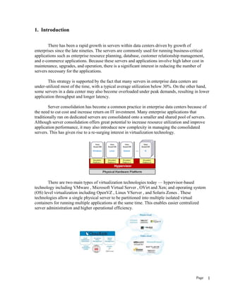
  • 22. 6. Virtualization Technical This project is organized as follows: an overview of virtualization techniques and a comparison between traditional hypervisor-based virtualization and container-based virtualization; it presents the experiments performed in order to evaluate both performance overhead and isolation; Section IV presents the related work. The conclusion and future work are presented in 6.1. Container-Based Virtualization Resource virtualization consists of using an intermediate software layer on top of an underlying system in order to provide abstractions of multiple virtual resources. In general, the virtualized resources are called virtual machines (VM) and can be seen as isolated execution contexts. There are a variety of virtualization techniques. Today, one of the most popular is the hypervisor-based virtualization, which has Xen, VMware and KVM as its main representatives. The hypervisor-based virtualization, in its most common form (hosted virtualization), consists of a Virtual Machine Monitor (VMM) on top of a host OS that provides a full abstraction of a VM. In this case, each VM has its own operating system that executes completely isolated from the others. This allows, for instance, the execution of multiple different operating systems on a single host. A lightweight alternative to the hypervisors is the container-based virtualization, also known as Operating Sys- tem Level virtualization. This kind of virtualization par titions the physical machines resources, creating multiple isolated user-space instances. Figure 1 shows the difference between container-based and hypervisor-based virtualization. As can be seem, Page 22
  • 23. while hypervisor-based virtualization provides abstraction for full guest OS’s (one per virtual ma- chine), container-based virtualization works at the operation system level, providing abstractions directly for the guest processes. In practice, hypervisors work at the hardware abstraction level and containers at the system call/ABI layer. Since the container-based virtualization works at the operating system level, all virtual instances share a single operating system kernel. For this reason, container-based virtualization is supposed to have a weaker isolation when compared to hypervisor-based virtualization. However, from the point of view of the users, each container looks and executes exactly like a stand-alone OS . The isolation in container-based virtualization is normally done by kernel namespaces . It is a feature of the Linux kernel that allow different processes to have a different view on the system. Since containers should not be able to interact with things outside, many global resources are wrapped in a layer of namespace that provides the illusion that the container is its own system. As examples of resources that can be isolated through namespaces, consider Filesystem, Process IDs (PID), Inter-Process Communication (IPC) and network . On the other hand, the resources management in container-based virtualization systems is normally done by Control Groups (cgroup) , which restricts a resource usage for process groups. For example, using cgroups it is possible to limit/prioritize CPU, memory and I/O usage for different containers. In some cases, some systems use their own implementations to perform the resource management due to the incompatibility with cgroups. Page 23
  • 24. The rest of this section presents the container-based virtualization systems studied in this work, which are Linux- VServer, OpenVZ and LXC. 6.1.1 Linux-VServer Linux-VServer is the oldest implementation of Linux container-based system. Instead of using namespaces to guarantee isolation, Linux-VServer introduced (through a patch) its own capabilities in the Linux kernel, such as process isolation, network isolation and CPU isolation. The Linux-VServer uses the traditional chroot system call to jail the file system inside the containers. That way it limits the scope of the file system for the processes. The processes isolation is accomplished through a global PID space, which hides all processes outside of a container’s scope and prohibits unwanted communications between processes of different containers. The benefits of this approach is the scalability for a large number of containers. However, the drawback is that the system is unable to implement usual virtualization techniques, such as live migration, checkpoint and resume, due the impossibility to re-instantiate processes The resource limits, such as memory consumption, num- ber of processes and file- handles, are performed using system calls (rlimit tool) provided by the Linux kernel. In addition, the Linux-VServer kernel includes even more capabilities for limiting another types of resources, such as the number of sockets and file descriptors opened. However, the recent versions of Linux-VServer includes support to cgroups, which can also be used to restrict the CPU us- age and memory consumption for containers. The Linux- VServer containers are managed by the util-vserver tools package . 6.1.2. OpenVZ OpenVZ offers some similar functionality to Linux- VServer. However, builds on kernel namespaces, making sure that every container has its own isolated subset of a resource. The system uses a PID namespace to guaran- tee the process isolation between different containers. It is so that every container processes has its own unique process IDs. Furthermore, unlike Linux-VServer, the PID namespace makes possible the use of usual virtualization techniques, such as live migration, checkpoint and resume. In OpenVZ, each container has its own shared memory segments, semaphores, and messages, due the IPC kernel namespace capability. Moreover, the OpenVZ also uses the network namespace. In this way, each container has its own network stack. This includes network devices, routing tables, firewall rules and so on. The system provides some network operation modes, such as Route-based, Bridge-based and Real Network based. The main differences between them is the layer of operation. While Route-based works in Layer 3 (network layer), Bridge-based works in Layer 2 (data link layer) and Real Network in Layer 1 (physical layer). In the Real Network mode, the host system administrator can assign a real network device (such as eth1) into a container, similar to Linux-VServer, providing the better network performance . The Disk Quota is a feature that allows to set up standard UNIX per-user and per- group disk limits for con- tainers . Finally, a similar approach of CPU scheduling is used for I/O. Page 24
  • 25. In this case, the second level scheduling uses Completely Fair Queuing (CFQ) Scheduler . For each container is given an I/O priority, and the scheduler dis- tributes the I/O bandwidth available according to priorities. In this way, no single container can saturate a channel, inter- fering with performance isolation. The OpenVZ containers are controled by the vzctl tool . 6.1.3. LXC In the same way as OpenVZ, LXC uses kernel names- paces to provide resource isolation among all containers. During the container startup, by default, the PIDs, IPCs and mount points are virtualized and isolated through the PID namespace, IPC namespace and file system namespace, respectively. In order to communicate with the outside world and to allow the network isolation, the system uses the network namespaces. Two configuration are offer by LXC in order to configure the network namespaces: Route-based and Bridge-based. Unlike Linux- VServer and OpenVZ, the re- source management is only allowed via cgroups. In network perspective, cgroups defines the configuration of network namespaces . The system uses multiple controllers over the standard linux CPU scheduler. The process control is accomplished by cgroups, which has function of limiting the CPU usage and isolating containers and processes; I/O operations are controlled by CFQ scheduler, as in OpenVZ. In this system, the containers are controled by the lxc- tool. 6.2 Install OVirt 6.2.1 Install oVirt Engine (Fedora / Red Hat Enterprise Linux / CentOS) oVirt Engine is the control center of the oVirt environment. It allows you to define hosts, configure data centers, add storage, define networks, create virtual machines, manage user permissions and use templates from one central location. 1. Install Fedora 19 (or Red Hat Enterprise Linux 6.5 or CentOS 6.5) on a server. When prompted for the software packages to install, select the minimal install option. See the Fedora Installation Guide or Red Hat Enterprise Linux 6 Installation Guide for more details. 2. After you have installed your server, update all the packages on it. Run: # yum -y update Reboot your server for the updates to be applied. 3. Subscribe the server to the oVirt project repository. For oVirt 3.5 install oVirt-release35.rpm. For oVirt 3.4 install oVirt-release34.rpm # yum install http://plain.resources.oVirt.org/pub/yum-repo/oVirt-release35.rpm 4. You are now ready to install the oVirt Engine. Run the following command: Page 25
  • 26. # yum -y install oVirt-engine This command will download the oVirt Engine installation software and resolve all dependencies. 5. When the packages have finished downloading, run the installer: # engine-setup 6. The installer will take you through a series of interactive questions as listed in the following example. If you do not enter a value when prompted, the installer uses the default settings which are stated in [ ] brackets. Example 1: oVirt Engine installation [ INFO ] Stage: Initializing [ INFO ] Stage: Environment setup Configuration files: ['/etc/oVirt-engine-setup.conf.d/10- packaging.conf'] Log file: /var/log/oVirt-engine/setup/oVirt-engine-setup- 20140310163840.log Version: otopi-1.2.0_rc2 (otopi-1.2.0-0.7.rc2.fc19) [ INFO ] Stage: Environment packages setup [ INFO ] Stage: Programs detection [ INFO ] Stage: Environment setup [ INFO ] Stage: Environment customization --== PRODUCT OPTIONS ==-- --== PACKAGES ==-- [ INFO ] Checking for product updates... [ INFO ] No product updates found --== NETWORK CONFIGURATION ==-- Host fully qualified DNS name of this server [server.name]: example.oVirt.org Setup can automatically configure the firewall on this system. Note: automatic configuration of the firewall may overwrite current settings. Do you want Setup to configure the firewall? (Yes, No) [Yes]: [ INFO ] firewalld will be configured as firewall manager. --== DATABASE CONFIGURATION ==-- Where is the Engine database located? (Local, Remote) [Local]: Setup can configure the local postgresql server automatically for the engine to run. This may conflict with existing applications. Would you like Setup to automatically configure postgresql and create Engine database, or prefer to perform that manually? (Automatic, Manual) [Automatic]: --== OVIRT ENGINE CONFIGURATION ==-- Application mode (Both, Virt, Gluster) [Both]: Page 26
  • 27. Default storage type: (NFS, FC, ISCSI, POSIXFS) [NFS]: Engine admin password: Confirm engine admin password: --== PKI CONFIGURATION ==-- Organization name for certificate [oVirt.org]: --== APACHE CONFIGURATION ==-- Setup can configure apache to use SSL using a certificate issued from the internal CA. Do you wish Setup to configure that, or prefer to perform that manually? (Automatic, Manual) [Automatic]: Setup can configure the default page of the web server to present the application home page. This may conflict with existing applications. Do you wish to set the application as the default page of the web server? (Yes, No) [Yes]: --== SYSTEM CONFIGURATION ==-- Configure WebSocket Proxy on this machine? (Yes, No) [Yes]: Configure an NFS share on this server to be used as an ISO Domain? (Yes, No) [Yes]: Local ISO domain path [/var/lib/exports/iso-20140310143916]: Local ISO domain ACL - note that the default will restrict access to example.oVirt.org only, for security reasons [example.oVirt.org(rw)]: Local ISO domain name [ISO_DOMAIN]: --== MISC CONFIGURATION ==-- --== END OF CONFIGURATION ==-- Important points to note: • The default ports 80 and 443 must be available to access the manager on HTTP and HTTPS respectively. • If you elect to configure an NFS share it will be exported from the machine on which the manager is being installed. • The storage type that you select will be used to create a data center and cluster. You will then be able to attach storage to these from the Web Administration Portal. • The default ACL for the ISO_DOMAIN NFS export is allowing access to the current machine only. You need to provide read/write access to any host that will need to attach to this domain. 7. You are then presented with a summary of the configurations you have selected. Type yes to accept them. Example 2: Confirm Engine installation settings Page 27
  • 28. [ INFO ] Stage: Setup validation --== CONFIGURATION PREVIEW ==-- Engine database name : engine Engine database secured connection : False Engine database host : localhost Engine database user name : engine Engine database host name validation : False Engine database port : 5432 NFS setup : True PKI organization : oVirt.org Application mode : both Firewall manager : firewalld Update Firewall : True Configure WebSocket Proxy : True Host FQDN : example.oVirt.org NFS export ACL : 0.0.0.0/0.0.0.0(rw) NFS mount point : /var/lib/exports/iso- 20140310143916 Datacenter storage type : nfs Configure local Engine database : True Set application as default page : True Configure Apache SSL : True Please confirm installation settings (OK, Cancel) [OK]: 8. The installation commences. The following message displays, indicating that the installation was successful. Example 3: Successful installation [ INFO ] Stage: Transaction setup [ INFO ] Stopping engine service [ INFO ] Stopping websocket-proxy service [ INFO ] Stage: Misc configuration [ INFO ] Stage: Package installation [ INFO ] Stage: Misc configuration [ INFO ] Creating PostgreSQL 'engine' database [ INFO ] Configuring PostgreSQL [ INFO ] Creating Engine database schema [ INFO ] Creating CA [ INFO ] Configuring WebSocket Proxy [ INFO ] Generating post install configuration file '/etc/oVirt-engine- setup.conf.d/20-setup-oVirt-post.conf' [ INFO ] Stage: Transaction commit [ INFO ] Stage: Closing up --== SUMMARY ==-- SSH fingerprint: <SSH_FINGERPRINT> Internal CA: <CA_FINGERPRINT> Web access is enabled at: http://example.oVirt.org:80/oVirt-engine https://example.oVirt.org:443/oVirt-engine Page 28
  • 29. Please use the user "admin" and password specified in order to login into oVirt Engine --== END OF SUMMARY ==-- [ INFO ] Starting engine service [ INFO ] Restarting httpd [ INFO ] Restarting nfs services [ INFO ] Generating answer file '/var/lib/oVirt- engine/setup/answers/20140310163837-setup.conf' [ INFO ] Stage: Clean up Log file is located at /var/log/oVirt-engine/setup/oVirt-engine-setup- 20140310163604.log [ INFO ] Stage: Pre-termination [ INFO ] Stage: Termination [ INFO ] Execution of setup completed successfully **** Installation completed successfully ****** 6.2.2 Install Hosts After you have installed the oVirt Engine, install the hosts to run your virtual machines. In oVirt, you can use either oVirt Node, Fedora or CentOS as hosts. 6.2.3 Install oVirt Node This document provides instructions for installing oVirt Node using a CD. For alternative methods including PXE networks or USB devices, see the oVirt Node deployment documentation. Before installing the oVirt Node, you need to download the hypervisor image and create a bootable CD with the image. 6.2.4 Download oVirt Node installation CD Download the latest version of oVirt Node from oVirt Node release and burn the ISO image onto a disc. Once you have created an oVirt Node installation CD, you can use it to boot the machine designated as your Node host. For this guide you will use the interactive installation where you are prompted to configure your settings in a graphical interface. Use the following keys to navigate around the installation screen: Menu Navigation Keys • Use the Up and Down arrow keys to navigate between selections. Your selections are highlighted in white. • The Tab key allows you to move between fields. Page 29
  • 30. • Use the Spacebar to tick checkboxes, represented by [ ] brackets. A marked checkbox displays with an asterisk (*). • To proceed with the selected configurations, press the Enter key. 6.2.5 To configure oVirt Node installation settings 1. Insert the oVirt Node installation CD into the CD-ROM drive of the designated host machine and reboot the machine. When the boot splash screen displays, select Start oVirt Node to boot from the Node installation media. Press Enter. 2. On the installation confirmation screen, select Install Hypervisor and press Enter. 3. Select the appropriate keyboard layout for your system. 4. The installer automatically detects the drives attached to the system. The selected disk for booting the hypervisor is highlighted in white. Ensure that the local disk is highlighted, or use the arrow keys to select the correct disk. Select Continue and press Enter. 5. You are prompted to confirm your selection of the local drive, which is marked with an asterisk. Select Continue and press Enter. 6. Enter a password for local console access and confirm it. Select Install and press Enter. The oVirt Node partitions the local drive, then commences installation. 7. Once installation is complete, a dialog prompts you to Reboot the hypervisor. Press Enter to confirm. Remove the installation disc. 8. After the Node has rebooted, you will be taken to a login shell. Log in as the admin user with the password you provided during installation to enter the oVirt Node management console. 9. On the Node hypervisor management console, there are eleven tabs on the left. Press the Up and Down keys to navigate between the tabs and Tab or right-arrow to access them. a. Select the Network tab. Configure the following options: • Hostname: Enter the hostname in the format of hostname.domain.example.com. • DNS Server: Enter the Domain Name Server address in the format of 192.168.0.254. You can use up to two DNS servers. • NTP Server: Enter the Network Time Protocol server address in the format of oVirt.pool.ntp.org. This synchronizes the hypervisor's system clock with that of the Engine's. You can use up to two NTP servers. Select Apply and press Enter to save your network settings. • The installer automatically detects the available network interface devices to be used as the management network. Select the device and press Enter to access the interface configuration menu. Under IPv4 Settings, tick either the DHCP or Static checkbox. If you are using static IPv4 network configuration, fill in the IP Address, Netmask and Gateway fields. To confirm your network settings, select OK and press Enter. b. Select the oVirt Engine tab. Configure the following options: • Management Server: Enter the oVirt Engine domain name in the format of oVirt.demo.example.com. • Management Server Port: Enter the management server port number. The default is 443. Page 30
  • 31. • Connect to the oVirt Engine and Validate Certificate: Tick this checkbox if you wish to verify the oVirt Engine security certificate. • Set oVirt Engine Admin Password: This field allows you to specify the root password for the hypervisor, and enable SSH password authentication from the oVirt Engine. This field is optional, and is covered in more detail in the oVirt Installation Guide. c. Select Apply and press Enter. A dialog displays, asking you to connect the hypervisor to the oVirt Engine and validate its certificate. Select Approve and press Enter. A message will display notifying you that the manager configuration has been successfully updated. d. Accept all other default settings. For information on configuring security, logging, kdump and remote storage, refer to the oVirt Node deployment instructions. e. Finally, select the Status tab. Select Restart and press Enter to reboot the host and apply all changes. You have now successfully installed the oVirt Node. Repeat this procedure if you wish to use more hypervisors. The following sections will provide instructions on how to approve the hypervisors for use with the oVirt Engine. 6.2.6 Install Fedora or CentOS Host You now know how to install a oVirt Node. In addition to hypervisor hosts, you can also reconfigure servers which are running Fedora to be used as virtual machine hosts. 6.2.7 To install a Fedora 19 host 1. On the machine designated as your Fedora host, install Fedora 19. A minimal installation is sufficient. 2. Log in to your Fedora host as the root user. 3. Install the oVirt-release35 or "oVirt-release34" package using yum, this package configures your system to receive updates from the oVirt project's software repository: # yum localinstall http://plain.resources.oVirt.org/pub/yum-repo/oVirt-release35.rpm 4. The oVirt platform uses a number of network ports for management and other virtualization features. oVirt Engine can make the necessary firewall adjustments automatically while adding your host. Alternatively, you may adjust your Fedora host's firewall settings to allow access to the required ports by configuring iptables rules. Modify the /etc/sysconfig/iptables file so it resembles the following example: :INPUT ACCEPT [0:0] :FORWARD ACCEPT [0:0] :OUTPUT ACCEPT [10765:598664] -A INPUT -m state --state RELATED,ESTABLISHED -j ACCEPT -A INPUT -p icmp -j ACCEPT Page 31
  • 32. -A INPUT -i lo -j ACCEPT -A INPUT -p tcp --dport 22 -j ACCEPT -A INPUT -p tcp --dport 16514 -j ACCEPT -A INPUT -p tcp --dport 54321 -j ACCEPT -A INPUT -p tcp -m multiport --dports 5634:6166 -j ACCEPT -A INPUT -p tcp -m multiport --dports 49152:49216 -j ACCEPT -A INPUT -p tcp -m state --state NEW -A INPUT -j REJECT --reject-with icmp-host-prohibited -A FORWARD -m physdev ! --physdev-is-bridged -j REJECT --reject-with icmp- host-prohibited COMMIT 5. Ensure that the iptables service is configured to start on boot and has been restarted, or started for the first time if it was not already running. Run the following commands: # chkconfig iptables on # service iptables restart 6. Some versions of Fedora come without the tar command installed by default, specially if you make a minimal installation, but this command is required in order to configure the host from the engine, so install it if needed: # yum install tar 7. Check if NetworkManager is being used for the network interface that is going to be used between the engine and this host. If it is change it to No. NetworkManager interfers with the bridge setup later when deploying vdsm. This is atleast true for Fedora 19 but might work with Fedora >19. You have now successfully installed a Fedora host. As before, repeat this procedure if you wish to use more Linux hosts. Before you can start running virtual machines on your host, you have to manually add it to the oVirt Engine via the administration portal, which you will access in the next step. Page 32
  • 33. 7. Connect to oVirt Engine Now that you have installed the oVirt Engine and hosts, you can log in to the Engine administration portal to start configuring your virtualization environment. 7.1 Log in to the Administration Portal Ensure you have the administrator password configured during installation as instructed in Example 1: “oVirt Engine installation”. To connect to oVirt web management portal 1. Open a browser and navigate to https://192.168.0.208. Substitute domain.example.com with the URL provided during installation. 2. If this is your first time connecting to the administration portal, oVirt Engine will issue security certificates for your browser. Click the link labelled this certificate to trust the ca.cer certificate. A pop-up displays, click Open to launch the Certificate dialog. Click Install Certificate and select to place the certificate in Trusted Root Certification Authorities store. 3. The portal login screen displays. Enter admin as your User Name, and enter the Password that you provided during installation. Ensure that your domain is set to Internal. Click Login. You have now successfully logged in to the oVirt web administration portal. Here, you can configure and manage all your virtual resources. The functions of the oVirt Engine graphical user interface are described in the following figure and list: Figure 1. Administration Portal Features Page 33
  • 34. 1. Header: This bar contains the name of the logged in user, the sign out button, the option to configure user roles. 2. Navigation Pane: This pane allows you to navigate between the Tree, Bookmarks and Tags tabs. In the Tree tab, tree mode allows you to see the entire system tree and provides a visual representation your virtualization environment's architecture. 3. Resources Tabs: These tabs allow you to access the resources of oVirt. You should already have a Default Data Center, a Default Cluster, a Host waiting to be approved, and available Storage waiting to be attached to the data center. 4. Results List: When you select a tab, this list displays the available resources. You can perform a task on an individual item or multiple items by selecting the item(s) and then clicking the relevant action button. If an action is not possible, the button is disabled. 5. Details Pane: When you select a resource, this pane displays its details in several subtabs. These subtabs also contain action buttons which you can use to make changes to the selected resource. Once you are familiar with the layout of the administration portal, you can start configuring your virtual environment. Page 34
  • 35. 8. Configure oVirt Now that you have logged in to the administration portal, configure your oVirt environment by defining the data center, host cluster, networks and storage. Even though this guide makes use of the default resources configured during installation, if you are setting up a oVirt environment with completely new components, you should perform the configuration procedure in the sequence given here. 8.1 Configure Data Centers A data center is a logical entity that defines the set of physical and logical resources used in a managed virtual environment. Think of it as a container which houses clusters of hosts, virtual machines, storage and networks. By default, oVirt creates a data center at installation. Its type is configured from the installation script. To access it, navigate to the Tree pane, click Expand All, and select the Default data center. On the Data Centers tab, the Default data center displays. Figure 2. Data Centers Tab The Default data center is used for this document, however if you wish to create a new data center see the oVirt Administration Guide. 8.2 Configure Clusters A cluster is a set of physical hosts that are treated as a resource pool for a set of virtual machines. Hosts in a cluster share the same network infrastructure, the same storage and the same type of CPU. They constitute a migration domain within which virtual machines can be moved from host to host. By default, oVirt creates a cluster at installation. To access it, navigate to the Tree pane, click Expand All and select the Default cluster. On the Clusters tab, the Default cluster displays. Page 35
  • 36. Figure 3. Clusters Tab For this document, the oVirt Node and Fedora hosts will be attached to the Default host cluster. If you wish to create new clusters, or live migrate virtual machines between hosts in a cluster, see the oVirt Administration Guide. 8.3 Configure Networks At installation, oVirt defines a Management network for the default data center. This network is used for communication between the manager and the host. New logical networks - for example for guest data, storage or display - can be added to enhance network speed and performance. All networks used by hosts and clusters must be added to data center they belong to. To access the Management network, click on the Clusters tab and select the default cluster. Click the Logical Networks tab in the Details pane. The oVirtmgmt network displays. Page 36
  • 37. Figure 4. Logical Networks Tab The oVirtmgmt Management network is used for this document, however if you wish to create new logical networks see the oVirt Administration Guide. 8.4 Configure Hosts You have already installed your oVirt Node and Fedora hosts, but before they can be used, they have to be added to the Engine. The oVirt Node is specifically designed for the oVirt platform, therefore it only needs a simple click of approval. Conversely, Fedora is a general purpose operating system, therefore reprogramming it as a host requires additional configuration. 8.4.1 Approve oVirt Node Host The Hypervisor you installed in Install oVirt Node is automatically registered with the oVirt platform. It displays in the oVirt Engine, and needs to be approved for use. To set up a oVirt Node host 1. On the Tree pane, click Expand All and select Hosts under the Default cluster. On the Hosts tab, select the name of your newly installed hypervisor. 2. Click the Approve button. The Edit and Approve Host dialog displays. Accept the defaults or make changes as necessary, then click OK. 3. The host status will change from Non Operational to Up. Page 37
  • 38. 8.4.2 Attach Fedora or CentOS Host In contrast to the oVirt Node host, the Fedora host you installed “Install Fedora Host” is not automatically detected. It has to be manually attached to the oVirt platform before it can be used. To attach a Fedora host 1. On the Tree pane, click Expand All and select Hosts under the Default cluster. On the Hosts tab, click New. 2. The New Host dialog displays. Figure 5. Attach Fedora Host Enter the details in the following fields: • Data Center: the data center to which the host belongs. Select the Default data center. • Host Cluster: the cluster to which the host belongs. Select the Default cluster. • Name: a descriptive name for the host. • Address: the IP address, or resolvable hostname of the host, which was provided during installation. • Root Password: the password of the designated host; used during installation of the host. • Configure iptables rules: This checkbox allows you to override the firewall settings on the host with the default rules for oVirt. Page 38
  • 39. 3. If you wish to configure this host for Out of Band (OOB) power management, select the Power Management tab. Tick the Enable Power Management checkbox and provide the required information in the following fields: • Address: The address of the host. • User Name: A valid user name for the OOB management. • Password: A valid, robust password for the OOB management. • Type: The type of OOB management device. Select the appropriate device from the drop down list. o alom Sun Advanced Lights Out Manager o apc American Power Conversion Master MasterSwitch network power switch o bladecenter IBM Bladecentre Remote Supervisor Adapter o drac5 Dell Remote Access Controller for Dell computers o eps ePowerSwitch 8M+ network power switch o ilo HP Integrated Lights Out standard o ilo3 HP Integrated Lights Out 3 standard o ipmilan Intelligent Platform Management Interface o rsa IBM Remote Supervisor Adaptor o rsb Fujitsu-Siemens RSB management interface o wti Western Telematic Inc Network PowerSwitch o cisco_ucs Cisco Unified Computing System Integrated Management Controller • Options: Extra command line options for the fence agent. Detailed documentation of the options available is provided in the man page for each fence agent. Click the Test button to test the operation of the OOB management solution. If you do not wish to configure power management, leave the Enable Power Management checkbox unmarked. 4. Click OK. If you have not configured power management, a pop-up window prompts you to confirm if you wish to proceed without power management. Select OK to continue. 5. The new host displays in the list of hosts with a status of Installing. Once installation is complete, the status will update to Reboot and then Awaiting. When the host is ready for use, its status changes to Up. To attach a CentOS 6.5 host Follow the instructions for a Fedora 19 host. You have now successfully configured your hosts to run virtual machines. The next step is to prepare data storage domains to house virtual machine disk images. Page 39
  • 40. 8.5 Configure Storage After configuring your logical networks, you need to add storage to your data center. oVirt uses a centralized shared storage system for virtual machine disk images and snapshots. Storage can be implemented using Network File System (NFS), Internet Small Computer System Interface (iSCSI) or Fibre Channel Protocol (FCP). Storage definition, type and function, are encapsulated in a logical entity called a Storage Domain. Multiple storage domains are supported. For this guide you will use two types of storage domains. The first is an NFS share for ISO images of installation media. You have already created this ISO domain during the oVirt Engine installation. The second storage domain will be used to hold virtual machine disk images. For this domain, you need at least one of the supported storage types. You have already set a default storage type during installation as described in Install oVirt Engine. Ensure that you use the same type when creating your data domain. Select your next step by checking the storage type you should use: 1. Navigate to the Tree pane and click the Expand All button. Under System, click Default. On the results list, the Default data center displays. 2. On the results list, the Storage Type column displays the type you should add. 3. Now that you have verified the storage type, create the storage domain - see one of: • Create an NFS Data Domain. • Create an iSCSI Data Domain. • Create an FCP Data Domain. Note: This document provides instructions to create a single storage domain, which is automatically attached and activated in the selected data center. If you wish to create additional storage domains within one data center, see the oVirt Administration Guide for instructions on activating storage domains. 8.5.1 Create an NFS Data Domain Because you have selected NFS as your default storage type during the Manager installation, you will now create an NFS storage domain. An NFS type storage domain is a mounted NFS share that is attached to a data center and used to provide storage for virtual machine disk images. Important: If you are using NFS storage, you must first create and export the directories to be used as storage domains from the NFS server. These directories must have their numerical user and group ownership set to 36:36 on the NFS server, to correspond to the vdsm user and kvm group respectively on the oVirt Engine server. You should create at least three NFS exports, one Page 40
  • 41. for each type of storage domain: data, iso and import/export. Typical NFS export names would be /export/data, /export/iso, and /export/import_export. In addition, these directories must be exported with the read write options (rw). A sample /etc/exports configuration might look like: # Please refer to the NFS documentation for your operating system on how to setup NFS security. # As they exist here, these shares have no access restrictions. /export/iso *(rw,sync,no_subtree_check,all_squash,anonuid=36,anongid=36) /export/data *(rw,sync,no_subtree_check,all_squash,anonuid=36,anongid=36) /export/import_export *(rw,sync,no_subtree_check,all_squash,anonuid=36,anongid=36) Once you have setup the NFS exports, you can now add them in oVirt. To add NFS storage: 1. Navigate to the Tree pane and click the Expand All button. Under System, select the Default data center and click on Storage. The available storage domains display on the results list. Click New Domain. 2. The New Storage dialog box displays. Configure the following options: • Name: Enter a suitably descriptive name. • Data Center: The Default data center is already pre-selected. • Domain Function / Storage Type: In the drop down menu, select Data → NFS. The storage domain types not compatible with the Default data center are grayed out. After you select your domain type, the Export Path field appears. Use Host: Select any of the hosts from the drop down menu. Only hosts which belong in the pre- selected data center will display in this list. • Export path: Enter the IP address or a resolvable hostname of the NFS server. The export path should be in the format of 192.168.0.10:/data or domain.example.com:/data 3. Click OK. The new NFS data domain displays on the Storage tab. It will remain with a Locked status while it is being prepared for use. When ready, it is automatically attached to the data center. You have created an NFS storage domain. Now, you need to attach an ISO domain to the data center and upload installation images so you can use them to create virtual machines. Proceed to Attach an ISO domain. Page 41
  • 42. 8.5.2 Create an iSCSI Data Domain Because you have selected iSCSI as your default storage type during the Manager installation, you will now create an iSCSI storage domain. oVirt platform supports iSCSI storage domains spanning multiple pre-defined Logical Unit Numbers (LUNs). To add iSCSI storage: 1. On the side pane, select the Tree tab. On System, click the + icon to display the available data centers. 2. Double click on the Default data center and click on Storage. The available storage domains display on the results list. Click New Domain. 3. The New Domain dialog box displays. Configure the following options: • Name: Enter a suitably descriptive name. • Data Center: The Default data center is already pre-selected. • Domain Function / Storage Type: In the drop down menu, select Data → iSCSI. The storage domain types which are not compatible with the Default data center are grayed out. After you select your domain type, the Use Host and Discover Targets fields display. • Use host: Select any of the hosts from the drop down menu. Only hosts which belong in this data center will display in this list. 4. To connect to the iSCSI target, click the Discover Targets bar. This expands the menu to display further connection information fields. Enter the required information: • Address: Enter the address of the iSCSI target. • Port: Select the port to connect to. The default is 3260. • User Authentication: If required, enter the username and password. 5. Click the Discover button to find the targets. The iSCSI targets display in the results list with a Login button for each target. 6. Click Login to display the list of existing LUNs. Tick the Add LUN checkbox to use the selected LUN as the iSCSI data domain. 7. Click OK. The new iSCSI data domain displays on the Storage tab. It will remain with a Locked status while it is being prepared for use. When ready, it is automatically attached to the data center. Page 42
  • 43. You have created an iSCSI storage domain. Now, you need to attach an ISO domain to the data center and upload installation images so you can use them to create virtual machines. Proceed to Attach an ISO domain. 8.5.3 Create an FCP Data Domain Because you have selected FCP as your default storage type during the Manager installation, you will now create an FCP storage domain. oVirt platform supports FCP storage domains spanning multiple pre-defined Logical Unit Numbers (LUNs). To add FCP storage: 1. On the side pane, select the Tree tab. On System, click the + icon to display the available data centers. 2. Double click on the Default data center and click on Storage. The available storage domains display on the results list. Click New Domain. 3. The New Domain dialog box displays. Configure the following options: • Name: Enter a suitably descriptive name. • Data Center: The Default data center is already pre-selected. • Domain Function / Storage Type: Select FCP. • Use Host: Select the IP address of either the hypervisor or Red Hat Enterprise Linux host. • The list of existing LUNs display. On the selected LUN, tick the Add LUN checkbox to use it as the FCP data domain. 4. Click OK. The new FCP data domain displays on the Storage tab. It will remain with a Locked status while it is being prepared for use. When ready, it is automatically attached to the data center. You have created an FCP storage domain. Now, you need to attach an ISO domain to the data center and upload installation images so you can use them to create virtual machines. Proceed to Attach an ISO domain 8.5.4 Attach an ISO domain You have defined your first storage domain to store virtual guest data, now it is time to configure your second storage domain, which will be used to store installation images for creating virtual machines. You have already created a local ISO domain during the installation of the oVirt Engine. To use this ISO domain, attach it to a data center. To attach the ISO domain Page 43
  • 44. 1. Navigate to the Tree pane and click the Expand All button. Click Default. On the results list, the Default data center displays. 2. On the details pane, select the Storage tab and click the Attach ISO button. 3. The Attach ISO Library dialog appears with the available ISO domain. Select it and click OK. 4. The ISO domain appears in the results list of the Storage tab. It displays with the Locked status as the domain is being validated, then changes to Inactive. 5. Select the ISO domain and click the Activate button. The status changes to Locked and then to Active. 8.5.6 Uploading ISO images Media images (CD-ROM or DVD-ROM in the form of ISO images) must be available in the ISO repository for the virtual machines to use. To do so, oVirt provides a utility that copies the images and sets the appropriate permissions on the file. The file provided to the utility and the ISO share have to be accessible from the oVirt Engine. Log in to the oVirt Engine server console to upload images to the ISO domain. To upload ISO images 1. Create or acquire the appropriate ISO images from boot media. Ensure the path to these images is accessible from the oVirt Engine server. 2. The next step is to upload these files. First, determine the available ISO domains by running: # engine-iso-uploader list You will be prompted to provide the admin user password which you use to connect to the administration portal. The tool lists the name of the ISO domain that you attached in the previous section. ISO Storage Domain List: local-iso-share Now you have all the information required to upload the required files. On the Engine console, copy your installation images to the ISO domain. For your images, run: # engine-iso-uploader upload -i local-iso-share [file1] [file2] .... [fileN] You will be prompted for the admin user password again. Provide it and press Enter. Note that the uploading process can be time consuming, depending on your storage performance. Page 44
  • 45. 3. After the images have been uploaded, check that they are available for use in the Manager administration portal. a. Navigate to the Tree and click the Expand All button. b. Under Storage, click on the name of the ISO domain. It displays in the results list. Click on it to display its details pane. c. On the details pane, select the Images tab. The list of available images should be populated with the files that you have uploaded. Now that you have successfully prepared the ISO domain for use, you are ready to start creating virtual machines. 9. Create Virtual Machines The final stage of setting up oVirt is the virtual machine lifecycle--spanning the creation, deployment and maintenance of virtual machines; using templates; and configuring user permissions. This section will also show you how to log in to the user portal and connect to virtual machines. On oVirt, you can create virtual machines from an existing template, as a clone, or from scratch. Once created, virtual machines can be booted using ISO images, a network boot (PXE) server, or a hard disk. This document provides instructions for creating a virtual machine using an ISO image. 9.1 Create a Fedora Virtual Machine 1. From the navigation tabs, select Virtual Machines. On the Virtual Machines tab, click New VM. 2. The “New Virtual Machine” popup appears. Page 45
  • 46. Figure 6: Create new linux virtual machine 3. Under General, your default Cluster and Template will be fine. 4. For Operating System, choose Red Hat Enterprise Linux (for i386/i686 Fedora) or Red Hat Enterprise Linux x64 (for x86_64 Fedora). 5. Under Optimized For, choose Desktop if you are creating a desktop VM, or Server if you are creating a server VM. 6. Add a Name (required) and a comment or description (optional). 7. Finally, attach a Network Interface (optional) to the VM by selecting one from the dropdown. 8. Click OK. Note: By clicking “Additional Options” you can configure other details such as memory and CPU resources. You can change these after creating a VM as well. 9. A New Virtual Machine - Guide Me window opens. This allows you to add storage disks to the virtual machine. Page 46
  • 47. Figure 7. New Virtual Machine 10. Click Configure Virtual Disks to add storage to the virtual machine. 11. Enter a Size for the disk. 12. Click OK. The parameters in the following figure such as Interface and Allocation Policy are recommended, but can be edited as necessary. Figure 8. Add Virtual Disk configurations 13. Close the Guide Me window by clicking Configure Later. Your new Fedora virtual machine will display in the Virtual Machines tab. You have now created your Fedora virtual machine. Before you can use your virtual machine, install an operating system on it. To install the Fedora guest operating system: Page 47
  • 48. 1. Right click the virtual machine and select Run Once. 2. Check “Attach CD” and choose a disk from the list Note: If you do not have any in the list, you need to upload one. 3. Click OK. Figure 9. Run once menu Retain the default settings for the other options and click OK to start the virtual machine. 4. Select the virtual machine and click the Console ( ) icon. This displays a window to the virtual machine, where you will be prompted to begin installing the operating system. For further instructions, see the Fedora Installation Guide. 5. After the installation has completed, shut down the virtual machine and reboot from the hard drive. You can now connect to your Fedora virtual machine and start using it. Post Install Additions Adding a few guest tools may improve your experience. Page 48
  • 49. • oVirt Guest Agent allows oVirt to show the Memory and Network utilization of the VM, the IP address of the VM, the installed Applications, Enable Single Sign On (SSO) and more. • Spice-vdagent allows for copy and paste support (text & image), better mouse functionality, and automatic adjustment of the screen resolution based on the size of your window. Add the oVirt Guest Agent by following the directions at How to install the guest agent in Fedora 9.2 Creating a Windows 7 VM 1. From the navigation tabs, select Virtual Machines. On the Virtual Machines tab, click New VM. Figure 10. The navigation tabs 2. The “New Virtual Machine” popup appears. Figure 11. Create new Windows virtual machine 3. Under General, your default Cluster and Template will be fine. Page 49
  • 50. 4. For Operating System, choose Windows 7 (for 32-bit Windows) or Windows7 x64 (for 64-bit Windows). 5. Under Optimized For, choose Desktop. 6. Add a Name (required) and a comment or description (optional). 7. Finally, attach a Network Interface (optional) to the VM by selecting one from the dropdown. 8. Click OK Note: By clicking “Additional Options” you can configure other details such as memory and CPU resources. You can change these after creating a VM as well. 9. A New Virtual Machine - Guide Me window opens. This allows you to add storage disks to the virtual machine. Figure 12. New Virtual Machine – Guide Me 10. Click Configure Virtual Disks to add storage to the virtual machine. 11. Enter a Size for the disk. 12. Click OK. The parameters in the following figure such as Interface and Allocation Policy are recommended, but can be edited as necessary. Page 50
  • 51. Figure 13. Add Virtual Disk configurations Note: As mentioned above When using the VirtIO interface (recommended) additional drivers are required at install time. You can use the IDE interface instead which does not require the additional drivers. The OS install guide covers both VirtIO and IDE interfaces below. 13. Close the Guide Me window by clicking Configure Later. Your new Windows 7 virtual machine will display in the Virtual Machines tab. You have now created your Windows 7 virtual machine. Before you can use your virtual machine you need to install an operating system on it. To install Windows guest operating system 1. Right click the virtual machine and select Run Once. 2. Check “Attach CD” and choose a disk from the list Note: If you do not have any in the list, you need to upload one. 3. Click OK. Page 51
  • 52. Figure 14. Run once menu Retain the default settings for the other options and click OK to start the virtual machine. 4. Select the virtual machine and click the Console ( ) icon. This displays a window to the virtual machine, where you will be prompted to begin installing the operating system. 5. Continue with the Windows 7 install as normal until you reach "Where do you want to install Windows?" 9.2.1 Installing with a VirtIO interface "Where do you want to install Windows?" does not show any disks. Click to expand this section. 9.2.2 Installing with a IDE interface "Where do you want to install Windows?" shows a disk to install to. Continue as normal. 9.2.3 Post Install Additions Drivers If you choose to use the VirtIO disk interface, the VirtIO network interface, or wish to use the oVirt Guest Tools through the VirtIO-Serial interface, you need to install additional drivers. Page 52
  • 53. Device Manager 1. On the console, open the Device Manger 2. On the Navigation Tabs, click Change CD Change CD 3. From the drop down list select the virtio CD and click ok. VirtIO CD 4. On the console, right click the first device that is missing drivers 5. Select "Update Driver Software", and then "Browse my computer for driver software" 6. Browse to the CD, Win7 folder. Choose the appropriate architecture (AMD64 for 64-bit, x86 for 32-bit) and click OK. 7. When prompted to install the driver, check "Always trust software from Red Hat, Inc" and click Install. 8. Repeat the above for the remaining missing drivers. 9.3 Using Templates Now that you know how to create a virtual machine, you can save its settings into a template. This template will retain the original virtual machine's configurations, including virtual disk and network interface settings, operating systems and applications. You can use this template to rapidly create replicas of the original virtual machine. Page 53
  • 54. 9.3.1 Create a Fedora Template To make a Fedora virtual machine template, use the virtual machine you created in Section 4.1.1, “Create a Fedora Virtual Machine” as a basis. Before it can be used, it has to be sealed. This ensures that machine-specific settings are not propagated through the template. To prepare a Fedora virtual machine for use as a template 1. Connect to the Fedora virtual machine to be used as a template. Flag the system for re- configuration by running the following command as root: # touch /.unconfigured 2. Remove ssh host keys. Run: # rm -rf /etc/ssh/ssh_host_* 3. Shut down the virtual machine. Run: # poweroff 4. The virtual machine has now been sealed, and is ready to be used as a template for Linux virtual machines. To create a template from a Fedora virtual machine 1. In the administration portal, click the Virtual Machines tab. Select the sealed Red Hat Enterprise Linux 6 virtual machine. Ensure that it has a status of Down. 2. Click Make Template. The New Virtual Machine Template displays. Page 54
  • 55. Figure 15. Make new virtual machine template Enter information into the following fields: • Name: Name of the new template • Description: Description of the new template • Host Cluster: The Host Cluster for the virtual machines using this template. • Make Private: If you tick this checkbox, the template will only be available to the template's creator and the administrative user. Nobody else can use this template unless they are given permissions by the existing permitted users. 3. Click OK. The virtual machine displays a status of "Image Locked" while the template is being created. The template is created and added to the Templates tab. During this time, the action buttons for the template remain disabled. Once created, the action buttons are enabled and the template is ready for use. 9.3.2 Clone a Red Hat Enterprise Linux Virtual Machine In the previous section, you created a Fedora template complete with pre-configured storage, networking and operating system settings. Now, you will use this template to deploy a pre- installed virtual machine. Page 55
  • 56. To clone a Fedora virtual machine from a template 1. Navigate to the Tree pane and click Expand All. Click the VMs icon under the Default cluster. On the Virtual Machines tab, click New Server. Figure 16. Create virtual machine based on Linux template • On the General tab, select the existing Linux template from the Based on Template list. • Enter a suitable Name and appropriate Description, then accept the default values inherited from the template in the rest of the fields. You can change them if needed. • Click the Resource Allocation tab. On the Provisioning field, click the drop down menu and select the Clone option. Page 56
  • 57. Figure 17. Set the provisioning to Clone 2. Retain all other default settings and click OK to create the virtual machine. The virtual machine displays in the Virtual Machines list. 9.3.3 Create a Windows Template To make a Windows virtual machine template, use the virtual machine you created Create a Windows Virtual Machine as a basis. Before a template for Windows virtual machines can be created, it has to be sealed with sysprep. This ensures that machine-specific settings are not propagated through the template. Note that the procedure below is applicable for creating Windows 7 and Windows 2008 R2 templates. If you wish to seal a Windows XP template, refer to the oVirt Administration Guide. To seal a Windows virtual machine with sysprep 1. In the Windows virtual machine to be used as a template, open a command line terminal and type regedit. 2. The Registry Editor window displays. On the left pane, expand HKEY_LOCAL_MACHINE → SYSTEM → SETUP. Page 57
  • 58. 3. On the main window, right click to add a new string value using New → String Value. Right click on the file and select Modify. When the Edit String dialog box displays, enter the following information in the provided text boxes: • Value name: UnattendFile • Value data: a:sysprep.inf 4. Launch sysprep from C:WindowsSystem32sysprepsysprep.exe • Under System Cleanup Action, select Enter System Out-of-Box-Experience (OOBE). • Tick the Generalize checkbox if you need to change the computer's system identification number (SID). • Under Shutdown Options, select Shutdown. 5. Click OK. The virtual machine will now go through the sealing process and shut down automatically. To create a template from an existing Windows machine 1. In the administration portal, click the Virtual Machines tab. Select the sealed Windows 7 virtual machine. Ensure that it has a status of Down and click Make Template. 2. The New Virtual Machine Template displays. Enter information into the following fields: • Name: Name of the new template • Description: Description of the new template • Host Cluster: The Host Cluster for the virtual machines using this template. • Make Public: Check this box to allow all users to access this template. 3. Click OK. In the Templates tab, the template displays the "Image Locked" status icon while it is being created. During this time, the action buttons for the template remain disabled. Once created, the action buttons are enabled and the template is ready for use. You can now create new Windows machines using this template. 9.3.4 Create a Windows Virtual Machine from a Template This section describes how to create a Windows 7 virtual machine using the template created in Create a Windows Template. To create a Windows virtual machine from a template 1. Navigate to the Tree pane and click Expand All. Click the VMs icon under the Default cluster. On the Virtual Machines tab, click New Desktop. Page 58
  • 59. • Select the existing Windows template from the Based on Template list. • Enter a suitable Name and appropriate Description, and accept the default values inherited from the template in the rest of the fields. You can change them if needed. 2. Retain all other default setting and click OK to create the virtual machine. The virtual machine displays in the Virtual Machines list with a status of "Image Locked" until the virtual disk is created. The virtual disk and networking settings are inherited from the template, and do not have to be reconfigured. 3. Click the Run icon to turn it on. This time, the Run Once steps are not required as the operating system has already been installed onto the virtual machine hard drive. Click the green Console button to connect to the virtual machine. You have now learned how to create Fedora and Windows virtual machines with and without templates. Next, you will learn how to access these virtual machines from a user portal. 9.4 Using Virtual Machines Now that you have created several running virtual machines, you can assign users to access them from the user portal. You can use virtual machines the same way you would use a physical desktop. 9.4.1 Assign User Permissions oVirt has a sophisticated multi-level administration system, in which customized permissions for each system component can be assigned to different users as necessary. For instance, to access a virtual machine from the user portal, a user must have either UserRole or PowerUserRole permissions for the virtual machine. These permissions are added from the manager administration portal. For more information on the levels of user permissions refer to the oVirt Administration Guide. To assign PowerUserRole permissions 1. Navigate to the Tree pane and click Expand All. Click the VMs icon under the Default cluster. On the Virtual Machines tab, select the virtual machine you would like to assign a user to. 2. On the Details pane, navigate to the Permissions tab. Click the Add button. 3. The Add Permission to User dialog displays. Enter a Name, or User Name, or part thereof in the Search textbox, and click Go. A list of possible matches display in the results list. Page 59
  • 60. Figure 18. Add PowerUserRole Permission 4. Select the check box of the user to be assigned the permissions. Scroll through the Assign role to user list and select PowerUserRole. Click OK. 7.4.2 To log in to the User Portal 1. Open your browser and navigate to https://domain.example.com/UserPortal. Substitute domain.example.com with the oVirt Engine server address. 2. The login screen displays. Enter your User Name and Password, and click Login. You have now logged into the user portal. As you have PowerUserRole permissions, you are taken by default to the Extended User Portal, where you can create and manage virtual machines in addition to using them. This portal is ideal if you are a system administrator who has to provision multiple virtual machines for yourself or other users in your environment. Page 60
  • 61. Figure 19. The Extended User Portal You can also toggle to the Basic User Portal, which is the default (and only) display for users with UserRole permissions. This portal allows users to access and use virtual machines, and is ideal for everyday users who do not need to make configuration changes to the system. For more information, see the oVirt User Portal Guide. Figure 20. The Basic User Portal You have now completed the Quick Start Guide, and successfully set up oVirt. Page 61
  • 62. 10. Experiments This section studies the performance and isolation of container-based and hypervisor-based virtualization. We performed several experiments with the current linux container-based virtualization implementations: Linux VServer, OpenVZ and LXC. We also chose Xen as the representative of hypervisor-based virtualization, because it is considered one of the most mature and efficient imple- mentations of this kind of virtualization . Our experimental setup consists of four identical Dell PowerEdge R610 with two 2.27GHz Intel Xeon E5520 processors (with 8 cores each), 8M of L2 cache per core, 16GB of RAM and one NetXtreme II BCM5709 Gigabit Ethernet adapter. All nodes are inter-connected by a Dell PowerConnect 5548 Ethernet switch. The Ubuntu 10.04 LTS (Lucid Lynx) distribution was installed on all host machines and the default configurations were maintained, except for the kernel and packages that were compiled in order to satisfy the virtualization systems’ requirements. We know that different versions of the kernel may introduce gains and losses of performance that would influence the results of experiments. Hence, we took care of compiling the same kernel version for all systems. We chose the kernel version 2.6.32-28, because it has support to all sys- tems’ patches and configurations. Therefore, for OpenVZ, we patched the kernel (2.6.32-feoktistov) and installed the package vzctl (3.0.23-8), which is necessary to manage the OpenVZ containers. We have compiled the OpenVZ kernel with the official configuration file (.config) suggested by the OpenVZ developer team , in order to ensure that all OpenVZ kernel options were enabled. For Linux-VServer, we also patched the kernel (2.3.0.36.29.4) and installed the package util- vserver (0.30.216 r2842-2) to control the Linux-VServer containers. The LXC already has a mainline implementation in the official kernel source. Hence, we just need to install the LXC Page 62