SlideShare a Scribd company logo
1 of 16
Download to read offline
ISO6432 STANDARD CYLINDER SCWR SERIES
Equipped with switch holder and locking gasket
Switch is directly clipped into switch bracket,
featuring three-side contact, no rotation,
safe, reliable & easily adjustable
Stainless steel is used
Suitable for many different environment & application.
Bright silver metalic design provides elegant appearance.
Conforming to ISO6432 standard,
easy to use, & Complying with interchangeability.
CKD standard switch applicable
Switches can be optionally
mounted to meet different needs.
Interchangeable
φ8~φ16
S
φ20、25
ISO6432 STANDARD CYLINDER
SCWR Series
New Products
C-CC-1388A 1
CKD (China) Corporation
New Product
Variation Model
Bore size
(mm)
Standard stroke length(
10 15 20 25 30 35 40 45 50 60 80 100
Double acting·
single rod
SCWR
SCWR-L
φ8 ● ● ● ● ● ● ● ● ● ● ● ●
φ10 ● ● ● ● ● ● ● ● ● ● ● ●
φ12 ● ● ● ● ● ● ● ● ● ● ● ●
φ16 ● ● ● ● ● ● ● ● ● ● ● ●
φ20 ● ● ● ● ● ● ● ● ● ● ● ●
φ25 ● ● ● ● ● ● ● ● ● ● ● ●
SCWR-L
Without switch
With switch
〈How to order〉
Mounting
style
Model
No.
Switch
quantity
Switch
model No.
Stroke
length
Bore
size
F
E
D
C
B
A
00 10 30 T2H D
SCWR 00 10 30
SCWR-L-00-10-30-T2H-D
Model No.: ISO6432 standard cylinder
Model No :Double acting (with switch)
Mounting style :Basic
Bore size :φ10
Stroke length :30mm
Switch model No. :Proximity switch T2H, lead wire length 1m
Switch quantity :2
A
B
C
D
E
F
Series variation
ISO6432 Standard Cylinder
SCWR Series
●: Standard ◎: Option : Unavailable
gth(mm)
Min.
stroke
length
Max.
stroke
length
Middle
stroke
length
Mounting style
Switch
Basic
type
Rod
eye
with
thread
type
Rod
side
fl
ange
type
Head
side
fl
ange
type
One-side
axial
foot
type
Two-side
axial
foot
type
00 125 150 160 200 250 300 320 400 500 (mm) (mm) (mm) 00 CC FA FB LS LB
●
5
100
1
● ● ● ● ● ● ◎
● 100 ● ● ● ● ● ● ◎
● ● ● ● ● 200 ● ● ● ● ● ● ◎
● ● ● ● ● 200 ● ● ● ● ● ● ◎
● ● ● ● ● ● ● ● ● ● 650 ● ● ● ● ● ● ◎
● ● ● ● ● ● ● ● ● ● 650 ● ● ● ● ● ● ◎
ISO6432 Standard Cylinder
SCWR Series
●Bore size: φ8/φ10/φ12/φ16/φ20/φ25
Symbol:
Specifications
Description SCWR
Bore size mm φ8 φ10 φ12 φ16 φ20 φ25
Actuation Double acting
Working fluid Clean compressed air
Max. working pressure MPa 1.0
Min. working pressure MPa 0.1
Withstanding pressure MPa 1.6
Ambient temperature ℃ -10 to 60 (no freezing)
Port size M5 G1/8
Stroke tolerance mm
+1.0
0
Stroke length 0 to 100mm:
+1.5
0
Stroke length 100 to 200mm:
+2.0
0
Stroke length above 200mm:
+2.4
0
Working piston speed mm/s 50 to 500
Cushion Rubber cushion
Lubrication Not required (when lubrication, use turbine oil Class 1 ISO VG32)
Allowable energy absorption J 0.020 0.035 0.060 0.090 0.166 0.308
Stroke length
Bore size
(mm)
Standard stroke (mm) Max. stroke (mm) Min. stroke (mm)
φ8
10, 15, 20, 25, 30, 35, 40, 45, 50, 60, 80, 100 100
5
φ10
φ12 10, 15, 20, 25, 30, 35, 40, 45, 50, 60, 80, 100, 125, 150,
160, 200 200
φ16
φ20 10, 15, 20, 25, 30, 35, 40, 45, 50, 60, 80, 100, 125, 150,
160, 200, 250, 300, 320, 400, 500 650
φ25
Note: Middle stroke lengths are available in 1 mm increments.
Switch specifications
Description
Proximity 2-wire Proximity 3-wire Reed 2-wire
T2H/T2V T2WH/T2WV T3H/T3V T3WH/T3WV T0H/T0V T5H/T5V
Applications Programmable controller Programmable controller, relay Programmable controller, relay
Programmable controller, relay IC
circuit (No indicator), serial connection
Output mode - NPN output - -
Power voltage - DC 10 to 28 V - -
Load voltage DC 10 to 30V DC 24 V±10% DC 30 V or less DC 12/24 V AC 110 V DC 5/12/24 V AC 110 V
Load current 5 to 20mA 100mA or less 50 mA or less 5 to 50mA 7 to 20mA 50 mA or less 20mA or less
Light
LED
(On lighting)
Red/green LED
(On lighting)
LED
(On lighting)
Red/green LED
(On lighting)
LED
(On lighting)
No indicator
Leaking current 1mA or less 10μA or less 0 mA 0 mA
Note: Switches are attached at shipment for φ8 to φ16 cylinders, and installed at shipment for φ20 to φ25 cylinders.
1
Description Mounting bracket weight
Additional weight
of rod eye with
thread (CC)
Product weight
with 0mm stroke
Additional
weight per 10mm
stroke
Switch weight
(only 1 pc
included)
Bore size
(mm)
One-side axial
foot LS
Rod side
flange FA
Head side
flange FB
Two-side axial
foot LB
φ8 20 16 19 53 -7 31 2.1
20
φ10 20 16 20 54 -6 34 2.3
φ12 43 38 49 114 -6 79 3.8
φ16 43 38 48 113 -7 76 5.4
φ20 88 81 88 212 -23 164 9.8
25
φ25 88 81 90 214 -21 222 13.5
Cylinder weight
<Example> Product weight of SCWR-L-LS-10-30-TOH-D
●Mounting bracket weight (Axial foot) ……… 20g
●Product weight with 0mm stroke …………… 34g
●Additional weight with 30mm stroke………… 2.3×30/10=6.9g
●Switch weight ………………………………… 2×20=40g
●Product weight………………………………… 20+34+6.9+40=100.9g
(Unit: g)
Min. stroke length with switch(mm)
Switch quantity Mounted on different surfaces Mounted on same surface
Bore size 1 2 1 2
φ8
5 10 5 28
φ10
φ12
φ16
Switch quantity
1 2 3
Proximity Reed Proximity Reed Proximity Reed
Bore size T2, T3 T2W, T3W T0, T5 T2, T3 T2W, T3W T0, T5 T2, T3 T2W, T3W T0, T5
φ20 10 25 30 25 50 55 50
φ25 10 25 30 25 50 55 50
SCWRSeries
Specifications
2
SCWR T0H 10
SCWR T 10
How to order
Without switch
With switch
Precautions for model selection
Note: No magnet is mounted on the piston for cylinders
without switch; Switches are installed at shipment for
φDQGijFOLQGHUV
Example of model number
SCWR-L-00-10-30-T2H-D
Model: ISO6432 standard cylinder
 0RGHO1R : Double acting (with switch)
Mounting style : Basic
Bore size : φ10
Stroke length : 30mm
 6ZLWFKPRGHO1R3UR[LPLWVZLWFK7+OHDGZLUHOHQJWKP
Switch quantity : 2
How to order switch
●6ZLWFKERGVZLWFKIL[LQJEDQG
6ZLWFKPRGHO1R
(Following page)
Bore size
(Following page)
Bore size
(Following page)
●6ZLWFKIL[LQJEDQG
SCWR 10 30
SCWR-L 00 10 30 T2H D
00
Model No.
A
C:Bore size
C
D:Stroke length
D
F:Switch model No.
E
G:Switch quantity
F
SCWR T0H
●Switch body only (φ8~φ16)
SCWR T
●6LQJOHVZLWFKIL[LQJEUDFNHW XQDYDLODEOHIRUφ20 and φFOLQGHUV
6ZLWFKPRGHO1R
(Following page)
E
SW T0H
●Switch body only (φ20 and φ
6ZLWFKPRGHO1R
(Following page)
E
E C
C
A
B
C
D
E
F
Switch quantity
R
H
D
T
1 on rod side
1 on head side
7ZR
7KUHH
F
Symbol
Model No.
SCWR
SCWR-L
Double acting
Double acting · with switch
Description
A
Mounting style
00
CC
FA
FB
LS
LB
B
Basic type
Rod eye with thread type
Rod side flange type
+HDGVLGHIODQJHWSH
2QHVLGHD[LDOIRRWWSH
7ZRVLGHD[LDOIRRWWSH
8
10
12
16
20
25
φ8
φ10
φ12
φ16
φ20
φ
c
C Bore size(mm)
Bore size
φ8
φ10
φ12
φ16
φ20
φ
~100
~200
~
100
200

Stroke length Middle stroke length
3HUPP
0D[VWURNH
d
D Stroke length(mm)
Blank
3
5
1m(Standard)
3m
P
Switch model No.
Linear type wire
T0H※
T5H※
T2H※
T3H※
T2WH※
T3WH※
T0V※
T5V※
T2V※
T3V※
T2WV※
T3WV※
L type wire
※Lead wire length
Contact
Reed
3UR[LPLW
Display mode Lead wire
1-color indicator
No indicator
1-color indicator
2-color indicator
2-wire
2-wire
3-wire
2-wire
3-wire
E
B:Mounting style
B
SCWRSeries
3
Internal structure and parts list
No. Parts name Material Remarks No. Parts name Material Remarks
1 Piston rod Stainless steel 12 Head cover Aluminum alloy Hard anodized
2 Rod nut Steel 13 Phill screw Stainless steel With switch only
3 Mounting nut Steel 14 Fixing bracket Stainless steel With switch only
4 Rod packing Nitrile rubber 15 Phill screw Stainless steel With switch only
5 Rod cover Aluminum alloy Hard anodized 16 Band Stainless steel With switch only
6 Cylinder tube Stainless steel 17 Lock nut Stainless steel With switch only
7 Cushion packing seal Urethane rubber 18 Bush Self-lubricating bearing Aluminum alloy for φ8 cylinders
8 Left piston Aluminum alloy 19 Support ring Resin
9 Piston seal Nitrile rubber 20 Spacer Steel
10 Piston magnet With switch only 21 Nut Steel
11 Right piston Aluminum alloy 22 Switch rail Stainless steel With switch only
Note: This product cannot be disassembled.
Double acting·single rod
●SCWR
●SCWR-L (with switch)
A part
A part is φ8
φ8~φ16
φ20~φ25
SCWRSeries
Internal structure and parts list
4
Symbol Basic dimensions of basic type (00)
Bore size (mm) A B BF D E EE G J KV KK KW BE MD MM D’ E’ QA
φ8 12 7 13 17.5 14.9 M5 9.7 8 19 M4×0.7 7 M12×1.25 12 4 17.5 14.9 5.7
φ10 12 7 13 17.5 14.9 M5 9.7 8 19 M4×0.7 7 M12×1.25 12 4 17.5 14.9 5.7
φ12 16 10 17 21.5 18 M5 10.1 10.1 24 M6×1 8 M16×1.5 16 6 21.5 18 5.6
φ16 16 10 17 21.5 18 M5 13.6 13.6 24 M6×1 8 M16×1.5 16 6 21.5 18 9.1
Symbol Basic dimensions of rod eye with thread type (CC)
Bore size (mm) A B BF D E EE G J KK BE L MR CD EW F MD MM D’ E’
φ8 12 7 13 17.5 14.9 M5 9.7 12 M4×0.7 M12×1.25 6 10 4 8 12 12 4 17.5 14.9
φ10 12 7 13 17.5 14.9 M5 9.7 12 M4×0.7 M12×1.25 6 10 4 8 12 12 4 17.5 14.9
φ12 16 10 17 21.5 18 M5 10.1 16.1 M6×1 M16×1.5 9 14 6 12 17 16 6 21.5 18
φ16 16 10 17 21.5 18 M5 13.6 18.6 M6×1 M16×1.5 9 13 6 12 17 16 6 21.5 18
Symbol
Basic dimensions of basic type (00) With switch
QB T WF LL X
T0, T5, T2, T3 T2W, T3W
P
Bore size (mm) RD HD RD HD
φ8 4 2.4 16 42 70 3 2.5 4.5 4.5 10.5
φ10 4 2.4 16 42 70 3.5 2.5 5.5 4 12.5
φ12 5.6 3.6 22 44 82 2 2.5 4.0 5.5 13
φ16 9.1 3.6 22 51 89 2 3.5 3.5 5 15.5
Symbol
Basic dimensions of rod eye with thread type (CC) With switch
QA QB T WF XC LL CA
T0, T5, T2, T3 T2W, T3W
P
Bore size (mm) RD HD RD HD
φ8 5.7 8 2.4 16 64 46 86 3 2.5 4.5 4.5 10.5
φ10 5.7 8 2.4 16 64 46 86 3.5 2.5 5.5 4 12.5
φ12 5.6 11.6 3.6 22 75 50 105 2 2.5 4.0 5.5 13
φ16 9.1 14.1 3.6 22 82 56 111 2 3.5 3.5 5 15.5
SCWRSeries
●Basic type (00)
●Rod eye with thread type (CC)
RD
WF
A
KK
KW
BF QA
G
LL+Stroke length
QB
J
X+Stroke length
Width across
flats B
φMM
BE E
E
KV
10
P
T
EE
φMD
h8
HD
φD
E'
E'
φD'
HD
WF
A
BF QA
G
QB
CA+Stroke length
φMM
φMD
h8
E
E
1
0
P
T
L MR
φCD H9
BE
J
EW d13
XC+Stroke length
Width across
flats B
EE
BE
F
RD
KK
LL+Stroke length
φD
E'
E'
φD'
Dimensions
5
Symbol Basic dimensions of basic type (00)
Bore size (mm) A B BF D E EE G J KV KK KW BE MD MM D’ E’ QA
φ20 20 13 14 32 27 G1/8 16 16 32 M8×1.25 8 M22×1.5 22 10 32 27 8
φ25 22 17 16 34 30 G1/8 16 16 32 M10×1.25 8 M22×1.5 22 12 34 30 8
Symbol Basic dimensions of rod eye with thread type (CC)
Bore size (mm) A B BF D E EE G J KK BE L MR CD EW F MD MM D’ E’
φ20 20 13 14 32 27 G1/8 16 16 M8×1.25 M22×1.5 12 12.2 8 16 17 22 10 32 27
φ25 22 17 16 34 30 G1/8 16 16 M10×1.25 M22×1.5 12 12.1 8 16 19 22 12 34 30
Symbol
Basic dimensions of basic type (00) With switch
QB T WF LL X
T0, T5, T2, T3 T2W, T3W
P P1 (Pθ)°
Bore size (mm) RD HD GC GD RD HD GC GD
φ20 8 5 24 66.2 110.2 8 7 4 3 10 9 6 5 17.3 19.5 22
φ25 8 6 28 69.1 119.1 9.5 8.5 5.5 4.5 11.5 10.5 7.5 6.5 19.8 22 18
Symbol
Basic dimensions of rod eye with thread type (CC) With switch
QA QB T WF XC LL CA
T0, T5, T2, T3 T2W, T3W
P P1 (Pθ)°
Bore size (mm) RD HD GC GD RD HD GC GD
φ20 8 8 5 24 95 66.2 127.2 8 7 4 3 10 9 6 5 17.3 19.5 22
φ25 8 8 6 28 104 69.1 138.1 9.5 8.5 5.5 4.5 11.5 10.5 7.5 6.5 19.8 22 18
SCWRSeries
Dimensions
Dimensions
●Basic type (00)
●Rod eye with thread type (CC)
KK
Width across
flats B φMD
h8
φMM
E
BE
RD
HD
GC
GD
A WF LL+Stroke length
X+Stroke length
T
BF G
J
KW
QA
EE
QB
E
φD
P
θ
P1 P
8
E'
φD'
KV
E'
KK Width across
flats B
φMD
h8
φMM
E
BE L
F
P
θ
RD
HD
GC
GD
A WF LL+Stroke length
CA+Stroke length
T
BF G
J
QA
EE QB
E
φD
P1 P
8
E'
E'
EW d13
φCD H9
XC+Stroke length
MR
φD'
6
Mounting model No. Bore size (mm) FD FF FH FL FM FT
SCWR-FA-8 φ8 4.5 13 22 30 40 3
SCWR-FA-10 φ10 4.5 13 22 30 40 3
SCWR-FA-12 φ12 5.5 18 30 40 52 4
SCWR-FA-16 φ16 5.5 18 30 40 52 4
SCWR-FA-20 φ20 6.6 19 40 50 66 5
SCWR-FA-25 φ25 6.6 23 40 50 66 5
Mounting model No. Bore size (mm) FD FF FH FL FM FT
SCWR-FB-8 φ8 4.5 65 22 30 40 3
SCWR-FB-10 φ10 4.5 65 22 30 40 3
SCWR-FB-12 φ12 5.5 76 30 40 52 4
SCWR-FB-16 φ16 5.5 82 30 40 52 4
SCWR-FB-20 φ20 6.6 95.2 40 50 66 5
SCWR-FB-25 φ25 6.6 102.1 40 50 66 5
Dimensions
●Rod side flange type (FA)
● Head side flange type (FB)
SCWRSeries
FL
FM
FH
FT
FF
2-φFD
FL
FM
FH
FT
FF+Stroke length
2-φFD
7
Mounting model No. Bore size (mm) LA LB LC LD LF LH LK LR LS LT
SCWR-LS-8 φ8 5 5 11 4.5 24 16 10 25 35 3
SCWR-LS-10 φ10 5 5 11 4.5 24 16 10 25 35 3
SCWR-LS-12 φ12 8 6 14 5.5 32 20 15 32 44 4
SCWR-LS-16 φ16 8 6 14 5.5 32 20 15 32 44 4
SCWR-LS-20 φ20 7 8 17 6.6 36 25 20 40 54 5
SCWR-LS-25 φ25 11 8 17 6.6 40 25 20 40 54 5
Dimensions
●One-side axial foot type (LS)
SCWRSeries
Dimensions
Mounting model No. Bore size (mm) LA LB LC LD LE LF LG LH LK LR LS LT
SCWR-LB-8 φ8 5 5 11 4.5 68 24 30 16 10 25 35 3
SCWR-LB-10 φ10 5 5 11 4.5 68 24 30 16 10 25 35 3
SCWR-LB-12 φ12 8 6 14 5.5 78 32 30 20 15 32 44 4
SCWR-LB-16 φ16 8 6 14 5.5 84 32 36 20 15 32 44 4
SCWR-LB-20 φ20 7 8 17 6.6 100.2 36 42.2 25 20 40 54 5
SCWR-LB-25 φ25 11 8 17 6.6 103.1 40 45.1 25 20 40 54 5
●Two-side axial foot type (LB)
LC
LF
LR
LB LC
LG+Stroke length
LA LE+Stroke length
2-φLD
LB
LS
LT
LH
LK
LR
LS
LT
LH
LK
LC LB
LF
LA
2-φLD
8
Safety Precautions
Be sure to read this section before use.
1 This product is designed and manufactured as a general industrial machine part.
Therefore, it must be handled by an operator with sufficient knowledge and experience.
2 Use the product within the specifications range.
3 Observe industrial standards and legal regulations, etc., pertaining to the safety of equipment design and management.
ISO4414, JIS B 8370 (General Rules for Pneumatic Systems)
JFPS2008 (Principles for pneumatic cylinder selection and use)
Including High Pressure Gas Safety Act, Industrial Safety and Health Act, other safety rules, body standards and regulations, etc.
4 Do not operate, pipe, or remove devices before confirming safety.
5 Observe the following warnings and cautions to prevent accidents.
WARNING
■Precautions are ranked as DANGER, WARNING, and CAUTION in this section.
Danger: In the case where mishandled product operation may lead to fatalities or
serious injuries, and the urgency of a dangerous situation is high.
A dangerous situation may occur if handling is mistaken,
leading to fatal or serious injuries.
A dangerous situation may occur if handling is mistaken,
leading to minor injuries or property damage.
(DANGER)
Warning:
(WARNING)
Caution:
(CAUTION)
Note that some items indicated with CAUTION may lead to serious results depending on
the conditions. All items contain important information and must be observed.
Disclaimer regarding shipping
1 Warranty period
This warranty is valid for one (1) year after delivery to the customer's designated site.
2 Scope of warranty
3 Compatibility check
The customer is responsible for confirming the compatibility of CKD products with the customer's
systems, machines, and equipment.
When designing and manufacturing equipment using CKD products, the manufacturer is obligated to ensure that
the safety of the mechanism, pneumatic control circuit and/or water control circuit and the system that runs the
electrical controls are secured. It is important to select, use, handle, and maintain CKD products appropriately to
ensure their safe usage. Observe warnings and precautions, etc. to ensure device safety. Check that device safety
is ensured, and manufacture a safe device.
Use the product within the specifications range.
This product must be used within its stated specifications. In addition, never modify or additionally machine this product.
This product is intended for use in general industrial machinery equipment or parts. It is not intended for use outdoors or
for use under the following conditions or environments.
(Note that this product can be used when CKD is consulted prior to its usage and the customer consents to the CKD
product specifications. The customer should provide safety measures to avoid danger in the event of problems.)
● Use for applications requiring safety, including nuclear energy, railways, aircraft, marine vessels, vehicles, medical
devices, devices or applications in contact with beverages or foodstuffs, amusement devices, emergency cutoff circuits,
press machines, brake circuits, or safety devices or applications.
● Use for applications where life or assets could be significantly affected, and special safety measures are required.
Check that device safety is ensured, and manufacture a safe device.
● Inspect and service the machine and devices after confirming the safety of all systems related to this product.
● Note that there may be hot or charged sections even after operation is stopped.
● When inspecting or servicing the device, turn OFF the energy source (gas supply or water supply), turn OFF power to
the facility, and discharge any compressed air and fluid from the system to avoid gas leakage and leakage of electricity.
● When starting or restarting a machine or device that incorporates pneumatic components, make sure to secure system
safety, such as pop-out prevention measures.
In case any defect clearly attributable to CKD is found during the warranty period, CKD shall, at its own discretion, repair the
defect or replace the relevant product in whole or in part and at no cost, according to its own judgment.
Note that the following failures are excluded from the warranty scope:
① When used outside of conditions/environment described in product specifications.
② Failures resulting from factors other than the delivered product.
③ When used not for the intended purposes.
④ Failures resulting from modification or repair not related to CKD.
⑤ Failures caused by matters that could not be predicted with the technologies in practice when the product was delivered.
⑥ Failures resulting from natural disasters for which CKD is not liable.
As well, the warranty described herein is limited to the delivered product itself, and does not cover damages incurred due to
abnormality of the delivered product.
9
Product-specific cautions: ISO6432 SCWR series
Safety Precautions
Be sure to read this section before use.
Pneumatic Components
Install · Assemble · Adjust
OK
NG
ijD
above 0
above 0
above 0
above 3
above 3
above 3
above 0
above 0
above 0
above 3
above 3
above 3
A
A
1.General precautions
CAUTION
■To prevent switch malfunction, when mounting
cylinders with switch closely side-by-side,
observe the following distance requirements as
shown in Table 1 below.
Switch
Table 1: Dimensions of A
Table 2: Dimensions of D
Bore size (mm)
Switch T0·T5
Reed
T2·T3
Proximity
■To prevent switch malfunction, when mounting
cylinders with switch closely to other components,
observe the following distance requirements as
shown in Table 2 below.
Cylinder surface
Switch
Switch
φ8
φ10
φ12
φ16
φ20
φ25
above 21 above 26.5
above 21 above 30
above 34
above 15 above 25
above 35
above 35 above 46
above 41 above 53
Bore size (mm)
Switch T0·T5
Reed
T2·T3
Proximity
φ8
φ10
φ12
φ16
φ20
φ25
■Installation of pipe
Figure 2
Figure 3
Figure 1
Piping thread
M5
G1/8
Tightening torque(N·m)
1.0~1.5
3.0~5.0
1.Use a suitable torque wrench to tighten the pipe as shown
in Figure 1, applying force by hand as closely to the wrench
head as possible.
See the following table for tightening torque.
2.Figure 2 shows an incorrect use of a wrench, which is excessively
large; Figure 3 shows an incorrect way to apply force.
10
Install
・
Assemble
・
Adjust
■When moving the switch position in stroke direction
1.For an 1-color indicator switch, it is possible to perform fine
adjustment of approx. ±3mm from the factory set mounting
position. For adjustment amount in excess of ±3mm and fine
position adjustment of a 2-color indicator switch, please move
the band position.
2.Loosen the switch mounting screw, move the switch along the rail,
and tighten at a given position. For T2, T3, T0 and T5, tighten the
switch fixing screw with a minus screwdriver 5 to 6mm in handle
diameter, less than 2.4mm in front shape width and less than 0.3mm
in thickness (screwdriver for watchmaker, precision screwdriver,
etc.), using a tightening torque of 0.1~0.2 N·m.
3.There is a mark on the switch rail that is 4mm away from the
end face. Use it as a reference for mounting position during
switch replacement. The mark of switch rail is set at the factory
set maximum sensitivity position of the switch. When the switch
type is changed or the band is moved, the maximum sensitivity
position will become different, so adjust the position accordingly.
Note: For the switch mounting position, refer to the dimensions
of RH and HD in the “Dimension” drawing.
■φ20~25
■When moving the switch position in circle direction
●Loosen the band fixing screw, move the switch rail in circle
direction, and tighten the screw at a given position.
7LJKWHQLQJWRUTXHLVWR1‡P
■When moving the band position
●Loosen the band fixing screw, move the switch rail and band
along the cylinder tube, and tighten the screw at a desired
position.
Tightening torque is 0.6 to 0.8 N·m.
Switch mounting mark
CKD
TOH
Lock nut Switch Band
Switch rail Cylinder tube
CKD
TOH
Installation of T-type switch
1.Set the switch fixing bracket in the square hole of the switch
fixing band (SCWR-T-**) and mount it onto the cylinder, with
its tail facing upwards.
2.Adjust the position slowly with the switch screw, and fix by
tightening the screw at the most suitable position. When tighten-
ing, the upper surface of the washer of the switch fixing bracket
should firmly adhere to the switch.
Tightening torque: 0.1 to 0.15 N·m
3.Tighten the screw of the band.
Tightening torque: 0.1 to 0.15 N·m
■φ8~16
Tail
Tail of switch fixing
bracket facing upwards
SCWRSeries
Product-specific cautions
11
■Do not rotate the end cover.
1.General precautions
CAUTION CAUTION
Use and service
■If a cylinder is kept unused for long time, its
stroke length may become shorter than the
reference value with low pressure settings due
to variation of cushion rigidity. Therefore, test
run the cylinder several times, or allow it to
perform multiple operations or reciprocate
several times under high pressure.
Install
・
Assemble
・
Adjust
■When piping, use a hose joint
(with fixed reducer) and a speed controller.
■During operation, always ensure that axial load
is applied to the piston rod.
■When the front end of the piston rod is
connected to a work piece, do not apply the
tightening torque to the cylinder.
φ8
φ10
φ12
φ16
φ20
φ25
6±10%
14±10%
23±10%
Bore size (mm) Tightening torque(N·m)
■When tightening a hexagonal nut,
observe the following torque range.
■Do not apply any external horizontal force
(e.g. piping force) to the cylinder tube.
●Deformation of cylinder tube may result in unstable operation.
■Do not rotate the end cover.
●When mounting the cylinder and screwing the pipe joint
into the port, the end cover joint part may be damaged if
the end cover is rotated.
Ŷ,QVWDOODWLRQRIPRXQWLQJEUDFNHW
Figure 5
Figure 4
1.Put the mounting bracket onto the thread part of rod cover,
and then screw up the end cover nut;
2.Fix the mounting bracket by clamping the rod cover with one
wrench and tightening the end cover nut with another wrench,
as shown in Figure 4;
3.Figure 5 shows an example of incorrect installation, i.e. clamp-
ing the head cover with one wrench and tightening the end cover
nut with another wrench, which tends to cause damage to the
cylinder.
●When mounting the cylinder and screwing the pipe joint into
the port, damage may occur firstly to the end cover joint part
if the end cover is rotated.
Rod cover
Mounting bracket
Head cover
SCWRSeries
Product-specific cautions
12
TAIWAN CKD CORPORATION
CKD USA CORPORATION
CKD UK OFFICE
CKD EUROPE B.V.
CKD EUROPE BRANCH
CKD FRANKFURT
OFFICE
CKD CZECH OFFICE
CKD KOREA CORPORATION
CKD SINGAPORE PTE. LTD.
CKD CORPORATION BRANCH OFFICE
CKD VIETNAM
ENGINEERING CO.,LTD
PT CKD TRADING INDONESIA
M-CKD PRECISION SDN.BHD.
CKD THAI CORPORATION LTD.
CKD INDIA PRIVATE LTD.
CKD INDIA PRIVATE LTD. BANGALORE BRANCH
CKD(SHANGHAI) CORPORATION
:Distributors
CKD MEXICO, S. DE R.L. DE C.V.
ƔSpecifications are subject to change without notice.
2018.7.ACNBC
CKD Corporation 2018 All copy rights reserved.
Website http://www.ckd.co.jp/
U.S.A.
CKD USA CORPORATION
Ɣ CHICAGO HEADQUARTERS
4080 Winnetka Avenue, Rolling Meadows, IL 60008, USA
PHONE +1-847-368-0539 FAX +1-847-788-0575
· CINCINNATI OFFICE
· SAN ANTONIO OFFICE
· SAN JOSE OFFICE
· DETROIT OFFICE
Mexico
CKD MEXICO, S. DE R.L. DE C.V.
Cerrada la Noria No. 200 Int. A-01, Querétaro Park II,
Parque Industrial Querétaro, Santa Rosa Jáuregui,
Querétaro, C.P. 76220, México
PHONE +52-442-161-0624
Europe
CKD EUROPE B.V.
Beechavenue 125A, 1119 RB Schiphol-Rijk, The Netherlands
PHONE +31-23-554-1490
· GERMANY OFFICE
CKD CORPORATION EUROPE BRANCH
Ɣ SALES HEADQUARTERS
Beechavenue 125A, 1119 RB Schiphol-Rijk, The Netherlands
PHONE +31-23-554-1490
· CZECH OFFICE
· UK OFFICE
Malaysia
M-CKD PRECISION SDN.BHD.
Ɣ HEAD OFFICE
Lot No.6,Jalan Modal 23/2, Seksyen 23, Kawasan MIEL,
Fasa 8, 40300 Shah Alam,Selangor Darul Ehsan, Malaysia
PHONE +60-(0)3-5541-1468 FAX +60-(0)3-5541-1533
· JOHOR BAHRU BRANCH OFFICE
· PENANG BRANCH OFFICE
Thailand
CKD THAI CORPORATION LTD.
Ɣ SALES HEADQUARTERS
Suwan Tower, 14/1 Soi Saladaeng 1, North Sathorn Road,
Kwaeng Silom, Khet Bangrak, Bangkok 10500, Thailand
PHONE +66-(0)2-267-6300 FAX +66-(0)2-267-6305
· RAYONG OFFICE
· NAVANAKORN OFFICE
· EASTERN SEABOARD OFFICE
· LAMPHUN OFFICE
· KORAT OFFICE
· AMATANAKORN OFFICE
· PRACHINBURI OFFICE
· SARABURI OFFICE
Singapore
CKD SINGAPORE PTE. LTD.
No.33 Tannery Lane #04-01 Hoesteel Industrial
Building, Singapore 347789, Singapore
PHONE +65-67442623 FAX +65-67442486
CKD CORPORATION BRANCH OFFICE
No.33 Tannery Lane #04-01 Hoesteel Industrial
Building, Singapore 347789, Singapore
PHONE +65-67447260 FAX +65-68421022
India
CKD INDIA PRIVATE LTD.
Unit No. 607, 6th Floor, Welldone Tech Park, Sector 48,
Sohna Road, Gurgaon-122018, Haryana, India
PHONE +91-(0)124-418-8212
CKD INDIA PRIVATE LTD. BANGALORE BRANCH
No. 201/B, 2nd Floor, Museum Terraces Apartment, No. 29,
Museum Road, Bangalore-560001, Karnataka, India
PHONE +91-(0)80-4212-7008/7009 FAX +91-(0)80-4212-7007
Indonesia
PT CKD TRADING INDONESIA
Ɣ SALES HEADQUARTERS
Menara Bidakara 2, 18th Floor, Jl. Jend. Gatot Subroto Kav.
71-73, Pancoran, Jakarta 12870, Indonesia
PHONE +62 21-2938-6601 FAX +62 21-2906-9470
· SURABAYA OFFICE
Vietnam
CKD VIETNAM ENGINEERING CO.,LTD.
18th Floor, CMC Tower, Duy Tan Street, Cau Giay
District, Hanoi, Vietnam
PHONE +84-4-37957631 FAX +84-4-37957637
Taiwan
TAIWAN CKD CORPORATION
16F-3, No. 7, Sec. 3, New Taipei Blvd., Xinzhuang Dist.,
New Taipei City 242, Taiwan
PHONE +886-(0)2-8522-8198 FAX +886-(0)2-8522-8128
· HSINCHU OFFICE
· TAICHUNG OFFICE
· TAINAN OFFICE
China
CKD(SHANGHAI)CORPORATION
Ɣ SALES HEADQUARTERS / SHANGHAI PUXI OFFICE
Room 601, 6th Floor, Yuanzhongkeyan Building, No. 1905
Hongmei Road, Xinhui District, Shanghai 200233, China
PHONE +86-(0)21-61911888 FAX +86-(0)21-60905356
·SHANGHAI PUDONG OFFICE
· WUXI OFFICE
· HANGZHOU OFFICE
· NINGBO OFFICE
· NANJING OFFICE
· SUZHOU OFFICE
· KUNSHAN OFFICE
· BEIJING OFFICE
· TIANJIN OFFICE
· CHANGCHUN OFFICE
· DALIAN OFFICE
· QINGDAO OFFICE
· JINAN OFFICE
· YANTAI OFFICE
· SHENYANG OFFICE
· CHONGQING OFFICE
· CHENGDU OFFICE
· XIAN OFFICE
· WUHAN OFFICE
· ZHENGZHOU OFFICE
· CHANGSHA OFFICE
· GUANGZHOU OFFICE
· WEST SHENZHEN OFFICE
· EAST SHENZHEN OFFICE
· DONGGUAN OFFICE
· XIAMEN OFFICE
Korea
CKD KOREA CORPORATION
Ɣ HEADQUARTERS
(3rd Floor), 44, Sinsu-ro, Mapo-gu, Seoul 121-856, Korea
PHONE +82-(0)2-783-5201~5203 FAX +82-(0)2-783-5204
· SUWON OFFICE
· CHEONAN OFFICE
· ULSAN OFFICE
Ƒ2XML.RPDNLLW$LFKL-DSDQ
Ƒ3+21((0)568-74-1338 FAX +81-(0)568-77-3461
The goods and/or their replicas, the technology and/or software found in this catalog are subject to complementary export
regulations by Foreign Exchange and Foreign Trade Law of Japan.
If the goods and/or their replicas, the technology and/or software found in this catalog are to be exported, law requires that the
exporter makes sure that they will never be used for the development and/or manufacture of weapons for mass destruction.

More Related Content

Similar to SCWR ISO6432 - Cilindro Mini ISO CKD.PDF

Npm s320 specsheet
Npm s320 specsheetNpm s320 specsheet
Npm s320 specsheetElectromate
 
Nvd 812 check valves
Nvd 812 check valvesNvd 812 check valves
Nvd 812 check valveslogenatech
 
Reguladora de Fluxo - SC3W Series Specifications - ckd corporation
Reguladora de Fluxo - SC3W Series Specifications - ckd corporation Reguladora de Fluxo - SC3W Series Specifications - ckd corporation
Reguladora de Fluxo - SC3W Series Specifications - ckd corporation Júlio Gengo
 
Iai rcs2 cr_sa6d_specsheet
Iai rcs2 cr_sa6d_specsheetIai rcs2 cr_sa6d_specsheet
Iai rcs2 cr_sa6d_specsheetElectromate
 
Iai rcp2 ra8_c_ra8r_specsheet
Iai rcp2 ra8_c_ra8r_specsheetIai rcp2 ra8_c_ra8r_specsheet
Iai rcp2 ra8_c_ra8r_specsheetElectromate
 
Iai rcs2 cr_sa5c_specsheet
Iai rcs2 cr_sa5c_specsheetIai rcs2 cr_sa5c_specsheet
Iai rcs2 cr_sa5c_specsheetElectromate
 
Npm s120 specsheet
Npm s120 specsheetNpm s120 specsheet
Npm s120 specsheetElectromate
 
Lintech ball screw_ps062series_specsheet
Lintech ball screw_ps062series_specsheetLintech ball screw_ps062series_specsheet
Lintech ball screw_ps062series_specsheetElectromate
 
Lintech 160series specsheet
Lintech 160series specsheetLintech 160series specsheet
Lintech 160series specsheetElectromate
 
Iai rcs2 ss8_c_specsheet
Iai rcs2 ss8_c_specsheetIai rcs2 ss8_c_specsheet
Iai rcs2 ss8_c_specsheetElectromate
 
Iai rcp2 ss8_c_specsheet
Iai rcp2 ss8_c_specsheetIai rcp2 ss8_c_specsheet
Iai rcp2 ss8_c_specsheetElectromate
 
Iai rcp2 srgd4_r_specsheet
Iai rcp2 srgd4_r_specsheetIai rcp2 srgd4_r_specsheet
Iai rcp2 srgd4_r_specsheetElectromate
 
Ball joint manufacturer vardhman bearings
Ball joint manufacturer  vardhman bearings  Ball joint manufacturer  vardhman bearings
Ball joint manufacturer vardhman bearings vardhmanbearings2015
 
Iai rcs2 cr_sa7c_specsheet
Iai rcs2 cr_sa7c_specsheetIai rcs2 cr_sa7c_specsheet
Iai rcs2 cr_sa7c_specsheetElectromate
 
Iai rcs2 cr_sa5d_specsheet
Iai rcs2 cr_sa5d_specsheetIai rcs2 cr_sa5d_specsheet
Iai rcs2 cr_sa5d_specsheetElectromate
 
Bomba Dosadora Milroyal B
Bomba Dosadora Milroyal BBomba Dosadora Milroyal B
Bomba Dosadora Milroyal BVibropac
 
Npm s200 specsheet
Npm s200 specsheetNpm s200 specsheet
Npm s200 specsheetElectromate
 
Iai rcp2 cr_ss8c_specsheet
Iai rcp2 cr_ss8c_specsheetIai rcp2 cr_ss8c_specsheet
Iai rcp2 cr_ss8c_specsheetElectromate
 

Similar to SCWR ISO6432 - Cilindro Mini ISO CKD.PDF (20)

Npm s320 specsheet
Npm s320 specsheetNpm s320 specsheet
Npm s320 specsheet
 
Nvd 812 check valves
Nvd 812 check valvesNvd 812 check valves
Nvd 812 check valves
 
Reguladora de Fluxo - SC3W Series Specifications - ckd corporation
Reguladora de Fluxo - SC3W Series Specifications - ckd corporation Reguladora de Fluxo - SC3W Series Specifications - ckd corporation
Reguladora de Fluxo - SC3W Series Specifications - ckd corporation
 
Iai rcs2 cr_sa6d_specsheet
Iai rcs2 cr_sa6d_specsheetIai rcs2 cr_sa6d_specsheet
Iai rcs2 cr_sa6d_specsheet
 
Iai rcp2 ra8_c_ra8r_specsheet
Iai rcp2 ra8_c_ra8r_specsheetIai rcp2 ra8_c_ra8r_specsheet
Iai rcp2 ra8_c_ra8r_specsheet
 
Iai rcs2 cr_sa5c_specsheet
Iai rcs2 cr_sa5c_specsheetIai rcs2 cr_sa5c_specsheet
Iai rcs2 cr_sa5c_specsheet
 
Npm s120 specsheet
Npm s120 specsheetNpm s120 specsheet
Npm s120 specsheet
 
Ct mt 00000005mag_combibox
Ct mt 00000005mag_combiboxCt mt 00000005mag_combibox
Ct mt 00000005mag_combibox
 
Knife gate valve catalogue
Knife gate valve catalogueKnife gate valve catalogue
Knife gate valve catalogue
 
Lintech ball screw_ps062series_specsheet
Lintech ball screw_ps062series_specsheetLintech ball screw_ps062series_specsheet
Lintech ball screw_ps062series_specsheet
 
Lintech 160series specsheet
Lintech 160series specsheetLintech 160series specsheet
Lintech 160series specsheet
 
Iai rcs2 ss8_c_specsheet
Iai rcs2 ss8_c_specsheetIai rcs2 ss8_c_specsheet
Iai rcs2 ss8_c_specsheet
 
Iai rcp2 ss8_c_specsheet
Iai rcp2 ss8_c_specsheetIai rcp2 ss8_c_specsheet
Iai rcp2 ss8_c_specsheet
 
Iai rcp2 srgd4_r_specsheet
Iai rcp2 srgd4_r_specsheetIai rcp2 srgd4_r_specsheet
Iai rcp2 srgd4_r_specsheet
 
Ball joint manufacturer vardhman bearings
Ball joint manufacturer  vardhman bearings  Ball joint manufacturer  vardhman bearings
Ball joint manufacturer vardhman bearings
 
Iai rcs2 cr_sa7c_specsheet
Iai rcs2 cr_sa7c_specsheetIai rcs2 cr_sa7c_specsheet
Iai rcs2 cr_sa7c_specsheet
 
Iai rcs2 cr_sa5d_specsheet
Iai rcs2 cr_sa5d_specsheetIai rcs2 cr_sa5d_specsheet
Iai rcs2 cr_sa5d_specsheet
 
Bomba Dosadora Milroyal B
Bomba Dosadora Milroyal BBomba Dosadora Milroyal B
Bomba Dosadora Milroyal B
 
Npm s200 specsheet
Npm s200 specsheetNpm s200 specsheet
Npm s200 specsheet
 
Iai rcp2 cr_ss8c_specsheet
Iai rcp2 cr_ss8c_specsheetIai rcp2 cr_ss8c_specsheet
Iai rcp2 cr_ss8c_specsheet
 

More from Júlio Gengo

Absodex - Indexador Magnético - Mesa Indexadora CKD CORPORATION
Absodex - Indexador Magnético - Mesa Indexadora CKD CORPORATIONAbsodex - Indexador Magnético - Mesa Indexadora CKD CORPORATION
Absodex - Indexador Magnético - Mesa Indexadora CKD CORPORATIONJúlio Gengo
 
EXPLOSION PROOF CKD CORP A PROVA DE EXPLOSAO.pdf
EXPLOSION PROOF CKD CORP A PROVA DE EXPLOSAO.pdfEXPLOSION PROOF CKD CORP A PROVA DE EXPLOSAO.pdf
EXPLOSION PROOF CKD CORP A PROVA DE EXPLOSAO.pdfJúlio Gengo
 
Protocolos de Comunicação para Automação Pneumática - CKD CORPORATION AERODYN...
Protocolos de Comunicação para Automação Pneumática - CKD CORPORATION AERODYN...Protocolos de Comunicação para Automação Pneumática - CKD CORPORATION AERODYN...
Protocolos de Comunicação para Automação Pneumática - CKD CORPORATION AERODYN...Júlio Gengo
 
CKD - Pneumática para SALA LIMPA 2023.pdf
CKD - Pneumática para SALA LIMPA 2023.pdfCKD - Pneumática para SALA LIMPA 2023.pdf
CKD - Pneumática para SALA LIMPA 2023.pdfJúlio Gengo
 
3QR・3QB・3QE・3QZ Series -VALVULA 3 VIAS
3QR・3QB・3QE・3QZ Series -VALVULA 3 VIAS3QR・3QB・3QE・3QZ Series -VALVULA 3 VIAS
3QR・3QB・3QE・3QZ Series -VALVULA 3 VIASJúlio Gengo
 
Segmento Automotivo - CKD Corp.pdf
Segmento Automotivo - CKD Corp.pdfSegmento Automotivo - CKD Corp.pdf
Segmento Automotivo - CKD Corp.pdfJúlio Gengo
 
GPS3 GAP SWITCH - Sensor de Folga ・How to order・Dimensions(2MB).pdf
GPS3 GAP SWITCH - Sensor de Folga ・How to order・Dimensions(2MB).pdfGPS3 GAP SWITCH - Sensor de Folga ・How to order・Dimensions(2MB).pdf
GPS3 GAP SWITCH - Sensor de Folga ・How to order・Dimensions(2MB).pdfJúlio Gengo
 
CC-1196A-3 - Processos Automotivos
CC-1196A-3 - Processos AutomotivosCC-1196A-3 - Processos Automotivos
CC-1196A-3 - Processos AutomotivosJúlio Gengo
 
Automação Pneumática para Máquinas CKD CORP - AERODYNAMIC TECHNOLOGY
Automação Pneumática para Máquinas CKD CORP - AERODYNAMIC TECHNOLOGYAutomação Pneumática para Máquinas CKD CORP - AERODYNAMIC TECHNOLOGY
Automação Pneumática para Máquinas CKD CORP - AERODYNAMIC TECHNOLOGYJúlio Gengo
 
CKD para Automação Industrial - CC-667A
CKD para Automação Industrial - CC-667ACKD para Automação Industrial - CC-667A
CKD para Automação Industrial - CC-667AJúlio Gengo
 
Automação Pneumática para Processos de Solda - CKD CORP.
Automação Pneumática para Processos de Solda - CKD CORP. Automação Pneumática para Processos de Solda - CKD CORP.
Automação Pneumática para Processos de Solda - CKD CORP. Júlio Gengo
 
Gerador~Extrator de Nitrogênio CKD CORP. - Série: NS・NSU・PNA・NS-QFS
Gerador~Extrator de Nitrogênio CKD CORP. -  Série: NS・NSU・PNA・NS-QFSGerador~Extrator de Nitrogênio CKD CORP. -  Série: NS・NSU・PNA・NS-QFS
Gerador~Extrator de Nitrogênio CKD CORP. - Série: NS・NSU・PNA・NS-QFSJúlio Gengo
 
High Durability - HP SERIES - CC1421A - CKD CORPORATION - AEROTECH.pdf
High Durability - HP SERIES - CC1421A - CKD CORPORATION - AEROTECH.pdfHigh Durability - HP SERIES - CC1421A - CKD CORPORATION - AEROTECH.pdf
High Durability - HP SERIES - CC1421A - CKD CORPORATION - AEROTECH.pdfJúlio Gengo
 
P4 - Baterias Recarregaveis - CKD Corporation - AEROTECH.pdf
P4 - Baterias Recarregaveis -  CKD Corporation - AEROTECH.pdfP4 - Baterias Recarregaveis -  CKD Corporation - AEROTECH.pdf
P4 - Baterias Recarregaveis - CKD Corporation - AEROTECH.pdfJúlio Gengo
 
Automação Pneumática Sustentável - CKD CORP. AERODYNAMITEC TECHNOLOGY
Automação Pneumática Sustentável - CKD CORP. AERODYNAMITEC TECHNOLOGYAutomação Pneumática Sustentável - CKD CORP. AERODYNAMITEC TECHNOLOGY
Automação Pneumática Sustentável - CKD CORP. AERODYNAMITEC TECHNOLOGYJúlio Gengo
 
Catálogo Gas boosters ou propulsores de gás - GLOBE Benelux - Aerodynamic Tec...
Catálogo Gas boosters ou propulsores de gás - GLOBE Benelux - Aerodynamic Tec...Catálogo Gas boosters ou propulsores de gás - GLOBE Benelux - Aerodynamic Tec...
Catálogo Gas boosters ou propulsores de gás - GLOBE Benelux - Aerodynamic Tec...Júlio Gengo
 
CKD - Catálogo Geral - Automação Pneumática - Aerodynamic Technology
CKD - Catálogo Geral - Automação Pneumática - Aerodynamic TechnologyCKD - Catálogo Geral - Automação Pneumática - Aerodynamic Technology
CKD - Catálogo Geral - Automação Pneumática - Aerodynamic TechnologyJúlio Gengo
 
Catálogo Completo GLOBE AIR MOTORS
Catálogo Completo GLOBE AIR MOTORSCatálogo Completo GLOBE AIR MOTORS
Catálogo Completo GLOBE AIR MOTORSJúlio Gengo
 

More from Júlio Gengo (18)

Absodex - Indexador Magnético - Mesa Indexadora CKD CORPORATION
Absodex - Indexador Magnético - Mesa Indexadora CKD CORPORATIONAbsodex - Indexador Magnético - Mesa Indexadora CKD CORPORATION
Absodex - Indexador Magnético - Mesa Indexadora CKD CORPORATION
 
EXPLOSION PROOF CKD CORP A PROVA DE EXPLOSAO.pdf
EXPLOSION PROOF CKD CORP A PROVA DE EXPLOSAO.pdfEXPLOSION PROOF CKD CORP A PROVA DE EXPLOSAO.pdf
EXPLOSION PROOF CKD CORP A PROVA DE EXPLOSAO.pdf
 
Protocolos de Comunicação para Automação Pneumática - CKD CORPORATION AERODYN...
Protocolos de Comunicação para Automação Pneumática - CKD CORPORATION AERODYN...Protocolos de Comunicação para Automação Pneumática - CKD CORPORATION AERODYN...
Protocolos de Comunicação para Automação Pneumática - CKD CORPORATION AERODYN...
 
CKD - Pneumática para SALA LIMPA 2023.pdf
CKD - Pneumática para SALA LIMPA 2023.pdfCKD - Pneumática para SALA LIMPA 2023.pdf
CKD - Pneumática para SALA LIMPA 2023.pdf
 
3QR・3QB・3QE・3QZ Series -VALVULA 3 VIAS
3QR・3QB・3QE・3QZ Series -VALVULA 3 VIAS3QR・3QB・3QE・3QZ Series -VALVULA 3 VIAS
3QR・3QB・3QE・3QZ Series -VALVULA 3 VIAS
 
Segmento Automotivo - CKD Corp.pdf
Segmento Automotivo - CKD Corp.pdfSegmento Automotivo - CKD Corp.pdf
Segmento Automotivo - CKD Corp.pdf
 
GPS3 GAP SWITCH - Sensor de Folga ・How to order・Dimensions(2MB).pdf
GPS3 GAP SWITCH - Sensor de Folga ・How to order・Dimensions(2MB).pdfGPS3 GAP SWITCH - Sensor de Folga ・How to order・Dimensions(2MB).pdf
GPS3 GAP SWITCH - Sensor de Folga ・How to order・Dimensions(2MB).pdf
 
CC-1196A-3 - Processos Automotivos
CC-1196A-3 - Processos AutomotivosCC-1196A-3 - Processos Automotivos
CC-1196A-3 - Processos Automotivos
 
Automação Pneumática para Máquinas CKD CORP - AERODYNAMIC TECHNOLOGY
Automação Pneumática para Máquinas CKD CORP - AERODYNAMIC TECHNOLOGYAutomação Pneumática para Máquinas CKD CORP - AERODYNAMIC TECHNOLOGY
Automação Pneumática para Máquinas CKD CORP - AERODYNAMIC TECHNOLOGY
 
CKD para Automação Industrial - CC-667A
CKD para Automação Industrial - CC-667ACKD para Automação Industrial - CC-667A
CKD para Automação Industrial - CC-667A
 
Automação Pneumática para Processos de Solda - CKD CORP.
Automação Pneumática para Processos de Solda - CKD CORP. Automação Pneumática para Processos de Solda - CKD CORP.
Automação Pneumática para Processos de Solda - CKD CORP.
 
Gerador~Extrator de Nitrogênio CKD CORP. - Série: NS・NSU・PNA・NS-QFS
Gerador~Extrator de Nitrogênio CKD CORP. -  Série: NS・NSU・PNA・NS-QFSGerador~Extrator de Nitrogênio CKD CORP. -  Série: NS・NSU・PNA・NS-QFS
Gerador~Extrator de Nitrogênio CKD CORP. - Série: NS・NSU・PNA・NS-QFS
 
High Durability - HP SERIES - CC1421A - CKD CORPORATION - AEROTECH.pdf
High Durability - HP SERIES - CC1421A - CKD CORPORATION - AEROTECH.pdfHigh Durability - HP SERIES - CC1421A - CKD CORPORATION - AEROTECH.pdf
High Durability - HP SERIES - CC1421A - CKD CORPORATION - AEROTECH.pdf
 
P4 - Baterias Recarregaveis - CKD Corporation - AEROTECH.pdf
P4 - Baterias Recarregaveis -  CKD Corporation - AEROTECH.pdfP4 - Baterias Recarregaveis -  CKD Corporation - AEROTECH.pdf
P4 - Baterias Recarregaveis - CKD Corporation - AEROTECH.pdf
 
Automação Pneumática Sustentável - CKD CORP. AERODYNAMITEC TECHNOLOGY
Automação Pneumática Sustentável - CKD CORP. AERODYNAMITEC TECHNOLOGYAutomação Pneumática Sustentável - CKD CORP. AERODYNAMITEC TECHNOLOGY
Automação Pneumática Sustentável - CKD CORP. AERODYNAMITEC TECHNOLOGY
 
Catálogo Gas boosters ou propulsores de gás - GLOBE Benelux - Aerodynamic Tec...
Catálogo Gas boosters ou propulsores de gás - GLOBE Benelux - Aerodynamic Tec...Catálogo Gas boosters ou propulsores de gás - GLOBE Benelux - Aerodynamic Tec...
Catálogo Gas boosters ou propulsores de gás - GLOBE Benelux - Aerodynamic Tec...
 
CKD - Catálogo Geral - Automação Pneumática - Aerodynamic Technology
CKD - Catálogo Geral - Automação Pneumática - Aerodynamic TechnologyCKD - Catálogo Geral - Automação Pneumática - Aerodynamic Technology
CKD - Catálogo Geral - Automação Pneumática - Aerodynamic Technology
 
Catálogo Completo GLOBE AIR MOTORS
Catálogo Completo GLOBE AIR MOTORSCatálogo Completo GLOBE AIR MOTORS
Catálogo Completo GLOBE AIR MOTORS
 

Recently uploaded

Call Girls Service Nashik Vaishnavi 7001305949 Independent Escort Service Nashik
Call Girls Service Nashik Vaishnavi 7001305949 Independent Escort Service NashikCall Girls Service Nashik Vaishnavi 7001305949 Independent Escort Service Nashik
Call Girls Service Nashik Vaishnavi 7001305949 Independent Escort Service NashikCall Girls in Nagpur High Profile
 
Online banking management system project.pdf
Online banking management system project.pdfOnline banking management system project.pdf
Online banking management system project.pdfKamal Acharya
 
Structural Analysis and Design of Foundations: A Comprehensive Handbook for S...
Structural Analysis and Design of Foundations: A Comprehensive Handbook for S...Structural Analysis and Design of Foundations: A Comprehensive Handbook for S...
Structural Analysis and Design of Foundations: A Comprehensive Handbook for S...Dr.Costas Sachpazis
 
AKTU Computer Networks notes --- Unit 3.pdf
AKTU Computer Networks notes ---  Unit 3.pdfAKTU Computer Networks notes ---  Unit 3.pdf
AKTU Computer Networks notes --- Unit 3.pdfankushspencer015
 
BSides Seattle 2024 - Stopping Ethan Hunt From Taking Your Data.pptx
BSides Seattle 2024 - Stopping Ethan Hunt From Taking Your Data.pptxBSides Seattle 2024 - Stopping Ethan Hunt From Taking Your Data.pptx
BSides Seattle 2024 - Stopping Ethan Hunt From Taking Your Data.pptxfenichawla
 
Booking open Available Pune Call Girls Koregaon Park 6297143586 Call Hot Ind...
Booking open Available Pune Call Girls Koregaon Park  6297143586 Call Hot Ind...Booking open Available Pune Call Girls Koregaon Park  6297143586 Call Hot Ind...
Booking open Available Pune Call Girls Koregaon Park 6297143586 Call Hot Ind...Call Girls in Nagpur High Profile
 
UNIT-II FMM-Flow Through Circular Conduits
UNIT-II FMM-Flow Through Circular ConduitsUNIT-II FMM-Flow Through Circular Conduits
UNIT-II FMM-Flow Through Circular Conduitsrknatarajan
 
Introduction and different types of Ethernet.pptx
Introduction and different types of Ethernet.pptxIntroduction and different types of Ethernet.pptx
Introduction and different types of Ethernet.pptxupamatechverse
 
Porous Ceramics seminar and technical writing
Porous Ceramics seminar and technical writingPorous Ceramics seminar and technical writing
Porous Ceramics seminar and technical writingrakeshbaidya232001
 
MANUFACTURING PROCESS-II UNIT-2 LATHE MACHINE
MANUFACTURING PROCESS-II UNIT-2 LATHE MACHINEMANUFACTURING PROCESS-II UNIT-2 LATHE MACHINE
MANUFACTURING PROCESS-II UNIT-2 LATHE MACHINESIVASHANKAR N
 
MANUFACTURING PROCESS-II UNIT-1 THEORY OF METAL CUTTING
MANUFACTURING PROCESS-II UNIT-1 THEORY OF METAL CUTTINGMANUFACTURING PROCESS-II UNIT-1 THEORY OF METAL CUTTING
MANUFACTURING PROCESS-II UNIT-1 THEORY OF METAL CUTTINGSIVASHANKAR N
 
The Most Attractive Pune Call Girls Budhwar Peth 8250192130 Will You Miss Thi...
The Most Attractive Pune Call Girls Budhwar Peth 8250192130 Will You Miss Thi...The Most Attractive Pune Call Girls Budhwar Peth 8250192130 Will You Miss Thi...
The Most Attractive Pune Call Girls Budhwar Peth 8250192130 Will You Miss Thi...ranjana rawat
 
Glass Ceramics: Processing and Properties
Glass Ceramics: Processing and PropertiesGlass Ceramics: Processing and Properties
Glass Ceramics: Processing and PropertiesPrabhanshu Chaturvedi
 
(ANVI) Koregaon Park Call Girls Just Call 7001035870 [ Cash on Delivery ] Pun...
(ANVI) Koregaon Park Call Girls Just Call 7001035870 [ Cash on Delivery ] Pun...(ANVI) Koregaon Park Call Girls Just Call 7001035870 [ Cash on Delivery ] Pun...
(ANVI) Koregaon Park Call Girls Just Call 7001035870 [ Cash on Delivery ] Pun...ranjana rawat
 
Call for Papers - Educational Administration: Theory and Practice, E-ISSN: 21...
Call for Papers - Educational Administration: Theory and Practice, E-ISSN: 21...Call for Papers - Educational Administration: Theory and Practice, E-ISSN: 21...
Call for Papers - Educational Administration: Theory and Practice, E-ISSN: 21...Christo Ananth
 
Processing & Properties of Floor and Wall Tiles.pptx
Processing & Properties of Floor and Wall Tiles.pptxProcessing & Properties of Floor and Wall Tiles.pptx
Processing & Properties of Floor and Wall Tiles.pptxpranjaldaimarysona
 
VIP Call Girls Ankleshwar 7001035870 Whatsapp Number, 24/07 Booking
VIP Call Girls Ankleshwar 7001035870 Whatsapp Number, 24/07 BookingVIP Call Girls Ankleshwar 7001035870 Whatsapp Number, 24/07 Booking
VIP Call Girls Ankleshwar 7001035870 Whatsapp Number, 24/07 Bookingdharasingh5698
 

Recently uploaded (20)

Call Girls Service Nashik Vaishnavi 7001305949 Independent Escort Service Nashik
Call Girls Service Nashik Vaishnavi 7001305949 Independent Escort Service NashikCall Girls Service Nashik Vaishnavi 7001305949 Independent Escort Service Nashik
Call Girls Service Nashik Vaishnavi 7001305949 Independent Escort Service Nashik
 
Online banking management system project.pdf
Online banking management system project.pdfOnline banking management system project.pdf
Online banking management system project.pdf
 
(INDIRA) Call Girl Aurangabad Call Now 8617697112 Aurangabad Escorts 24x7
(INDIRA) Call Girl Aurangabad Call Now 8617697112 Aurangabad Escorts 24x7(INDIRA) Call Girl Aurangabad Call Now 8617697112 Aurangabad Escorts 24x7
(INDIRA) Call Girl Aurangabad Call Now 8617697112 Aurangabad Escorts 24x7
 
Structural Analysis and Design of Foundations: A Comprehensive Handbook for S...
Structural Analysis and Design of Foundations: A Comprehensive Handbook for S...Structural Analysis and Design of Foundations: A Comprehensive Handbook for S...
Structural Analysis and Design of Foundations: A Comprehensive Handbook for S...
 
AKTU Computer Networks notes --- Unit 3.pdf
AKTU Computer Networks notes ---  Unit 3.pdfAKTU Computer Networks notes ---  Unit 3.pdf
AKTU Computer Networks notes --- Unit 3.pdf
 
BSides Seattle 2024 - Stopping Ethan Hunt From Taking Your Data.pptx
BSides Seattle 2024 - Stopping Ethan Hunt From Taking Your Data.pptxBSides Seattle 2024 - Stopping Ethan Hunt From Taking Your Data.pptx
BSides Seattle 2024 - Stopping Ethan Hunt From Taking Your Data.pptx
 
Booking open Available Pune Call Girls Koregaon Park 6297143586 Call Hot Ind...
Booking open Available Pune Call Girls Koregaon Park  6297143586 Call Hot Ind...Booking open Available Pune Call Girls Koregaon Park  6297143586 Call Hot Ind...
Booking open Available Pune Call Girls Koregaon Park 6297143586 Call Hot Ind...
 
Water Industry Process Automation & Control Monthly - April 2024
Water Industry Process Automation & Control Monthly - April 2024Water Industry Process Automation & Control Monthly - April 2024
Water Industry Process Automation & Control Monthly - April 2024
 
UNIT-II FMM-Flow Through Circular Conduits
UNIT-II FMM-Flow Through Circular ConduitsUNIT-II FMM-Flow Through Circular Conduits
UNIT-II FMM-Flow Through Circular Conduits
 
Introduction and different types of Ethernet.pptx
Introduction and different types of Ethernet.pptxIntroduction and different types of Ethernet.pptx
Introduction and different types of Ethernet.pptx
 
Porous Ceramics seminar and technical writing
Porous Ceramics seminar and technical writingPorous Ceramics seminar and technical writing
Porous Ceramics seminar and technical writing
 
MANUFACTURING PROCESS-II UNIT-2 LATHE MACHINE
MANUFACTURING PROCESS-II UNIT-2 LATHE MACHINEMANUFACTURING PROCESS-II UNIT-2 LATHE MACHINE
MANUFACTURING PROCESS-II UNIT-2 LATHE MACHINE
 
MANUFACTURING PROCESS-II UNIT-1 THEORY OF METAL CUTTING
MANUFACTURING PROCESS-II UNIT-1 THEORY OF METAL CUTTINGMANUFACTURING PROCESS-II UNIT-1 THEORY OF METAL CUTTING
MANUFACTURING PROCESS-II UNIT-1 THEORY OF METAL CUTTING
 
The Most Attractive Pune Call Girls Budhwar Peth 8250192130 Will You Miss Thi...
The Most Attractive Pune Call Girls Budhwar Peth 8250192130 Will You Miss Thi...The Most Attractive Pune Call Girls Budhwar Peth 8250192130 Will You Miss Thi...
The Most Attractive Pune Call Girls Budhwar Peth 8250192130 Will You Miss Thi...
 
Glass Ceramics: Processing and Properties
Glass Ceramics: Processing and PropertiesGlass Ceramics: Processing and Properties
Glass Ceramics: Processing and Properties
 
(ANVI) Koregaon Park Call Girls Just Call 7001035870 [ Cash on Delivery ] Pun...
(ANVI) Koregaon Park Call Girls Just Call 7001035870 [ Cash on Delivery ] Pun...(ANVI) Koregaon Park Call Girls Just Call 7001035870 [ Cash on Delivery ] Pun...
(ANVI) Koregaon Park Call Girls Just Call 7001035870 [ Cash on Delivery ] Pun...
 
Call for Papers - Educational Administration: Theory and Practice, E-ISSN: 21...
Call for Papers - Educational Administration: Theory and Practice, E-ISSN: 21...Call for Papers - Educational Administration: Theory and Practice, E-ISSN: 21...
Call for Papers - Educational Administration: Theory and Practice, E-ISSN: 21...
 
Processing & Properties of Floor and Wall Tiles.pptx
Processing & Properties of Floor and Wall Tiles.pptxProcessing & Properties of Floor and Wall Tiles.pptx
Processing & Properties of Floor and Wall Tiles.pptx
 
VIP Call Girls Ankleshwar 7001035870 Whatsapp Number, 24/07 Booking
VIP Call Girls Ankleshwar 7001035870 Whatsapp Number, 24/07 BookingVIP Call Girls Ankleshwar 7001035870 Whatsapp Number, 24/07 Booking
VIP Call Girls Ankleshwar 7001035870 Whatsapp Number, 24/07 Booking
 
Roadmap to Membership of RICS - Pathways and Routes
Roadmap to Membership of RICS - Pathways and RoutesRoadmap to Membership of RICS - Pathways and Routes
Roadmap to Membership of RICS - Pathways and Routes
 

SCWR ISO6432 - Cilindro Mini ISO CKD.PDF

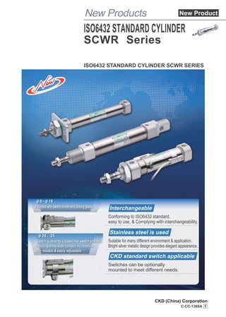
  • 1. ISO6432 STANDARD CYLINDER SCWR SERIES Equipped with switch holder and locking gasket Switch is directly clipped into switch bracket, featuring three-side contact, no rotation, safe, reliable & easily adjustable Stainless steel is used Suitable for many different environment & application. Bright silver metalic design provides elegant appearance. Conforming to ISO6432 standard, easy to use, & Complying with interchangeability. CKD standard switch applicable Switches can be optionally mounted to meet different needs. Interchangeable φ8~φ16 S φ20、25 ISO6432 STANDARD CYLINDER SCWR Series New Products C-CC-1388A 1 CKD (China) Corporation New Product
  • 2. Variation Model Bore size (mm) Standard stroke length( 10 15 20 25 30 35 40 45 50 60 80 100 Double acting· single rod SCWR SCWR-L φ8 ● ● ● ● ● ● ● ● ● ● ● ● φ10 ● ● ● ● ● ● ● ● ● ● ● ● φ12 ● ● ● ● ● ● ● ● ● ● ● ● φ16 ● ● ● ● ● ● ● ● ● ● ● ● φ20 ● ● ● ● ● ● ● ● ● ● ● ● φ25 ● ● ● ● ● ● ● ● ● ● ● ● SCWR-L Without switch With switch 〈How to order〉 Mounting style Model No. Switch quantity Switch model No. Stroke length Bore size F E D C B A 00 10 30 T2H D SCWR 00 10 30 SCWR-L-00-10-30-T2H-D Model No.: ISO6432 standard cylinder Model No :Double acting (with switch) Mounting style :Basic Bore size :φ10 Stroke length :30mm Switch model No. :Proximity switch T2H, lead wire length 1m Switch quantity :2 A B C D E F Series variation ISO6432 Standard Cylinder SCWR Series
  • 3. ●: Standard ◎: Option : Unavailable gth(mm) Min. stroke length Max. stroke length Middle stroke length Mounting style Switch Basic type Rod eye with thread type Rod side fl ange type Head side fl ange type One-side axial foot type Two-side axial foot type 00 125 150 160 200 250 300 320 400 500 (mm) (mm) (mm) 00 CC FA FB LS LB ● 5 100 1 ● ● ● ● ● ● ◎ ● 100 ● ● ● ● ● ● ◎ ● ● ● ● ● 200 ● ● ● ● ● ● ◎ ● ● ● ● ● 200 ● ● ● ● ● ● ◎ ● ● ● ● ● ● ● ● ● ● 650 ● ● ● ● ● ● ◎ ● ● ● ● ● ● ● ● ● ● 650 ● ● ● ● ● ● ◎
  • 4. ISO6432 Standard Cylinder SCWR Series ●Bore size: φ8/φ10/φ12/φ16/φ20/φ25 Symbol: Specifications Description SCWR Bore size mm φ8 φ10 φ12 φ16 φ20 φ25 Actuation Double acting Working fluid Clean compressed air Max. working pressure MPa 1.0 Min. working pressure MPa 0.1 Withstanding pressure MPa 1.6 Ambient temperature ℃ -10 to 60 (no freezing) Port size M5 G1/8 Stroke tolerance mm +1.0 0 Stroke length 0 to 100mm: +1.5 0 Stroke length 100 to 200mm: +2.0 0 Stroke length above 200mm: +2.4 0 Working piston speed mm/s 50 to 500 Cushion Rubber cushion Lubrication Not required (when lubrication, use turbine oil Class 1 ISO VG32) Allowable energy absorption J 0.020 0.035 0.060 0.090 0.166 0.308 Stroke length Bore size (mm) Standard stroke (mm) Max. stroke (mm) Min. stroke (mm) φ8 10, 15, 20, 25, 30, 35, 40, 45, 50, 60, 80, 100 100 5 φ10 φ12 10, 15, 20, 25, 30, 35, 40, 45, 50, 60, 80, 100, 125, 150, 160, 200 200 φ16 φ20 10, 15, 20, 25, 30, 35, 40, 45, 50, 60, 80, 100, 125, 150, 160, 200, 250, 300, 320, 400, 500 650 φ25 Note: Middle stroke lengths are available in 1 mm increments. Switch specifications Description Proximity 2-wire Proximity 3-wire Reed 2-wire T2H/T2V T2WH/T2WV T3H/T3V T3WH/T3WV T0H/T0V T5H/T5V Applications Programmable controller Programmable controller, relay Programmable controller, relay Programmable controller, relay IC circuit (No indicator), serial connection Output mode - NPN output - - Power voltage - DC 10 to 28 V - - Load voltage DC 10 to 30V DC 24 V±10% DC 30 V or less DC 12/24 V AC 110 V DC 5/12/24 V AC 110 V Load current 5 to 20mA 100mA or less 50 mA or less 5 to 50mA 7 to 20mA 50 mA or less 20mA or less Light LED (On lighting) Red/green LED (On lighting) LED (On lighting) Red/green LED (On lighting) LED (On lighting) No indicator Leaking current 1mA or less 10μA or less 0 mA 0 mA Note: Switches are attached at shipment for φ8 to φ16 cylinders, and installed at shipment for φ20 to φ25 cylinders. 1
  • 5. Description Mounting bracket weight Additional weight of rod eye with thread (CC) Product weight with 0mm stroke Additional weight per 10mm stroke Switch weight (only 1 pc included) Bore size (mm) One-side axial foot LS Rod side flange FA Head side flange FB Two-side axial foot LB φ8 20 16 19 53 -7 31 2.1 20 φ10 20 16 20 54 -6 34 2.3 φ12 43 38 49 114 -6 79 3.8 φ16 43 38 48 113 -7 76 5.4 φ20 88 81 88 212 -23 164 9.8 25 φ25 88 81 90 214 -21 222 13.5 Cylinder weight <Example> Product weight of SCWR-L-LS-10-30-TOH-D ●Mounting bracket weight (Axial foot) ……… 20g ●Product weight with 0mm stroke …………… 34g ●Additional weight with 30mm stroke………… 2.3×30/10=6.9g ●Switch weight ………………………………… 2×20=40g ●Product weight………………………………… 20+34+6.9+40=100.9g (Unit: g) Min. stroke length with switch(mm) Switch quantity Mounted on different surfaces Mounted on same surface Bore size 1 2 1 2 φ8 5 10 5 28 φ10 φ12 φ16 Switch quantity 1 2 3 Proximity Reed Proximity Reed Proximity Reed Bore size T2, T3 T2W, T3W T0, T5 T2, T3 T2W, T3W T0, T5 T2, T3 T2W, T3W T0, T5 φ20 10 25 30 25 50 55 50 φ25 10 25 30 25 50 55 50 SCWRSeries Specifications 2
  • 6. SCWR T0H 10 SCWR T 10 How to order Without switch With switch Precautions for model selection Note: No magnet is mounted on the piston for cylinders without switch; Switches are installed at shipment for φDQGijFOLQGHUV Example of model number SCWR-L-00-10-30-T2H-D Model: ISO6432 standard cylinder 0RGHO1R : Double acting (with switch) Mounting style : Basic Bore size : φ10 Stroke length : 30mm 6ZLWFKPRGHO1R3UR[LPLWVZLWFK7+OHDGZLUHOHQJWKP Switch quantity : 2 How to order switch ●6ZLWFKERGVZLWFKIL[LQJEDQG 6ZLWFKPRGHO1R (Following page) Bore size (Following page) Bore size (Following page) ●6ZLWFKIL[LQJEDQG SCWR 10 30 SCWR-L 00 10 30 T2H D 00 Model No. A C:Bore size C D:Stroke length D F:Switch model No. E G:Switch quantity F SCWR T0H ●Switch body only (φ8~φ16) SCWR T ●6LQJOHVZLWFKIL[LQJEUDFNHW XQDYDLODEOHIRUφ20 and φFOLQGHUV 6ZLWFKPRGHO1R (Following page) E SW T0H ●Switch body only (φ20 and φ 6ZLWFKPRGHO1R (Following page) E E C C A B C D E F Switch quantity R H D T 1 on rod side 1 on head side 7ZR 7KUHH F Symbol Model No. SCWR SCWR-L Double acting Double acting · with switch Description A Mounting style 00 CC FA FB LS LB B Basic type Rod eye with thread type Rod side flange type +HDGVLGHIODQJHWSH 2QHVLGHD[LDOIRRWWSH 7ZRVLGHD[LDOIRRWWSH 8 10 12 16 20 25 φ8 φ10 φ12 φ16 φ20 φ c C Bore size(mm) Bore size φ8 φ10 φ12 φ16 φ20 φ ~100 ~200 ~ 100 200 Stroke length Middle stroke length 3HUPP 0D[VWURNH d D Stroke length(mm) Blank 3 5 1m(Standard) 3m P Switch model No. Linear type wire T0H※ T5H※ T2H※ T3H※ T2WH※ T3WH※ T0V※ T5V※ T2V※ T3V※ T2WV※ T3WV※ L type wire ※Lead wire length Contact Reed 3UR[LPLW Display mode Lead wire 1-color indicator No indicator 1-color indicator 2-color indicator 2-wire 2-wire 3-wire 2-wire 3-wire E B:Mounting style B SCWRSeries 3
  • 7. Internal structure and parts list No. Parts name Material Remarks No. Parts name Material Remarks 1 Piston rod Stainless steel 12 Head cover Aluminum alloy Hard anodized 2 Rod nut Steel 13 Phill screw Stainless steel With switch only 3 Mounting nut Steel 14 Fixing bracket Stainless steel With switch only 4 Rod packing Nitrile rubber 15 Phill screw Stainless steel With switch only 5 Rod cover Aluminum alloy Hard anodized 16 Band Stainless steel With switch only 6 Cylinder tube Stainless steel 17 Lock nut Stainless steel With switch only 7 Cushion packing seal Urethane rubber 18 Bush Self-lubricating bearing Aluminum alloy for φ8 cylinders 8 Left piston Aluminum alloy 19 Support ring Resin 9 Piston seal Nitrile rubber 20 Spacer Steel 10 Piston magnet With switch only 21 Nut Steel 11 Right piston Aluminum alloy 22 Switch rail Stainless steel With switch only Note: This product cannot be disassembled. Double acting·single rod ●SCWR ●SCWR-L (with switch) A part A part is φ8 φ8~φ16 φ20~φ25 SCWRSeries Internal structure and parts list 4
  • 8. Symbol Basic dimensions of basic type (00) Bore size (mm) A B BF D E EE G J KV KK KW BE MD MM D’ E’ QA φ8 12 7 13 17.5 14.9 M5 9.7 8 19 M4×0.7 7 M12×1.25 12 4 17.5 14.9 5.7 φ10 12 7 13 17.5 14.9 M5 9.7 8 19 M4×0.7 7 M12×1.25 12 4 17.5 14.9 5.7 φ12 16 10 17 21.5 18 M5 10.1 10.1 24 M6×1 8 M16×1.5 16 6 21.5 18 5.6 φ16 16 10 17 21.5 18 M5 13.6 13.6 24 M6×1 8 M16×1.5 16 6 21.5 18 9.1 Symbol Basic dimensions of rod eye with thread type (CC) Bore size (mm) A B BF D E EE G J KK BE L MR CD EW F MD MM D’ E’ φ8 12 7 13 17.5 14.9 M5 9.7 12 M4×0.7 M12×1.25 6 10 4 8 12 12 4 17.5 14.9 φ10 12 7 13 17.5 14.9 M5 9.7 12 M4×0.7 M12×1.25 6 10 4 8 12 12 4 17.5 14.9 φ12 16 10 17 21.5 18 M5 10.1 16.1 M6×1 M16×1.5 9 14 6 12 17 16 6 21.5 18 φ16 16 10 17 21.5 18 M5 13.6 18.6 M6×1 M16×1.5 9 13 6 12 17 16 6 21.5 18 Symbol Basic dimensions of basic type (00) With switch QB T WF LL X T0, T5, T2, T3 T2W, T3W P Bore size (mm) RD HD RD HD φ8 4 2.4 16 42 70 3 2.5 4.5 4.5 10.5 φ10 4 2.4 16 42 70 3.5 2.5 5.5 4 12.5 φ12 5.6 3.6 22 44 82 2 2.5 4.0 5.5 13 φ16 9.1 3.6 22 51 89 2 3.5 3.5 5 15.5 Symbol Basic dimensions of rod eye with thread type (CC) With switch QA QB T WF XC LL CA T0, T5, T2, T3 T2W, T3W P Bore size (mm) RD HD RD HD φ8 5.7 8 2.4 16 64 46 86 3 2.5 4.5 4.5 10.5 φ10 5.7 8 2.4 16 64 46 86 3.5 2.5 5.5 4 12.5 φ12 5.6 11.6 3.6 22 75 50 105 2 2.5 4.0 5.5 13 φ16 9.1 14.1 3.6 22 82 56 111 2 3.5 3.5 5 15.5 SCWRSeries ●Basic type (00) ●Rod eye with thread type (CC) RD WF A KK KW BF QA G LL+Stroke length QB J X+Stroke length Width across flats B φMM BE E E KV 10 P T EE φMD h8 HD φD E' E' φD' HD WF A BF QA G QB CA+Stroke length φMM φMD h8 E E 1 0 P T L MR φCD H9 BE J EW d13 XC+Stroke length Width across flats B EE BE F RD KK LL+Stroke length φD E' E' φD' Dimensions 5
  • 9. Symbol Basic dimensions of basic type (00) Bore size (mm) A B BF D E EE G J KV KK KW BE MD MM D’ E’ QA φ20 20 13 14 32 27 G1/8 16 16 32 M8×1.25 8 M22×1.5 22 10 32 27 8 φ25 22 17 16 34 30 G1/8 16 16 32 M10×1.25 8 M22×1.5 22 12 34 30 8 Symbol Basic dimensions of rod eye with thread type (CC) Bore size (mm) A B BF D E EE G J KK BE L MR CD EW F MD MM D’ E’ φ20 20 13 14 32 27 G1/8 16 16 M8×1.25 M22×1.5 12 12.2 8 16 17 22 10 32 27 φ25 22 17 16 34 30 G1/8 16 16 M10×1.25 M22×1.5 12 12.1 8 16 19 22 12 34 30 Symbol Basic dimensions of basic type (00) With switch QB T WF LL X T0, T5, T2, T3 T2W, T3W P P1 (Pθ)° Bore size (mm) RD HD GC GD RD HD GC GD φ20 8 5 24 66.2 110.2 8 7 4 3 10 9 6 5 17.3 19.5 22 φ25 8 6 28 69.1 119.1 9.5 8.5 5.5 4.5 11.5 10.5 7.5 6.5 19.8 22 18 Symbol Basic dimensions of rod eye with thread type (CC) With switch QA QB T WF XC LL CA T0, T5, T2, T3 T2W, T3W P P1 (Pθ)° Bore size (mm) RD HD GC GD RD HD GC GD φ20 8 8 5 24 95 66.2 127.2 8 7 4 3 10 9 6 5 17.3 19.5 22 φ25 8 8 6 28 104 69.1 138.1 9.5 8.5 5.5 4.5 11.5 10.5 7.5 6.5 19.8 22 18 SCWRSeries Dimensions Dimensions ●Basic type (00) ●Rod eye with thread type (CC) KK Width across flats B φMD h8 φMM E BE RD HD GC GD A WF LL+Stroke length X+Stroke length T BF G J KW QA EE QB E φD P θ P1 P 8 E' φD' KV E' KK Width across flats B φMD h8 φMM E BE L F P θ RD HD GC GD A WF LL+Stroke length CA+Stroke length T BF G J QA EE QB E φD P1 P 8 E' E' EW d13 φCD H9 XC+Stroke length MR φD' 6
  • 10. Mounting model No. Bore size (mm) FD FF FH FL FM FT SCWR-FA-8 φ8 4.5 13 22 30 40 3 SCWR-FA-10 φ10 4.5 13 22 30 40 3 SCWR-FA-12 φ12 5.5 18 30 40 52 4 SCWR-FA-16 φ16 5.5 18 30 40 52 4 SCWR-FA-20 φ20 6.6 19 40 50 66 5 SCWR-FA-25 φ25 6.6 23 40 50 66 5 Mounting model No. Bore size (mm) FD FF FH FL FM FT SCWR-FB-8 φ8 4.5 65 22 30 40 3 SCWR-FB-10 φ10 4.5 65 22 30 40 3 SCWR-FB-12 φ12 5.5 76 30 40 52 4 SCWR-FB-16 φ16 5.5 82 30 40 52 4 SCWR-FB-20 φ20 6.6 95.2 40 50 66 5 SCWR-FB-25 φ25 6.6 102.1 40 50 66 5 Dimensions ●Rod side flange type (FA) ● Head side flange type (FB) SCWRSeries FL FM FH FT FF 2-φFD FL FM FH FT FF+Stroke length 2-φFD 7
  • 11. Mounting model No. Bore size (mm) LA LB LC LD LF LH LK LR LS LT SCWR-LS-8 φ8 5 5 11 4.5 24 16 10 25 35 3 SCWR-LS-10 φ10 5 5 11 4.5 24 16 10 25 35 3 SCWR-LS-12 φ12 8 6 14 5.5 32 20 15 32 44 4 SCWR-LS-16 φ16 8 6 14 5.5 32 20 15 32 44 4 SCWR-LS-20 φ20 7 8 17 6.6 36 25 20 40 54 5 SCWR-LS-25 φ25 11 8 17 6.6 40 25 20 40 54 5 Dimensions ●One-side axial foot type (LS) SCWRSeries Dimensions Mounting model No. Bore size (mm) LA LB LC LD LE LF LG LH LK LR LS LT SCWR-LB-8 φ8 5 5 11 4.5 68 24 30 16 10 25 35 3 SCWR-LB-10 φ10 5 5 11 4.5 68 24 30 16 10 25 35 3 SCWR-LB-12 φ12 8 6 14 5.5 78 32 30 20 15 32 44 4 SCWR-LB-16 φ16 8 6 14 5.5 84 32 36 20 15 32 44 4 SCWR-LB-20 φ20 7 8 17 6.6 100.2 36 42.2 25 20 40 54 5 SCWR-LB-25 φ25 11 8 17 6.6 103.1 40 45.1 25 20 40 54 5 ●Two-side axial foot type (LB) LC LF LR LB LC LG+Stroke length LA LE+Stroke length 2-φLD LB LS LT LH LK LR LS LT LH LK LC LB LF LA 2-φLD 8
  • 12. Safety Precautions Be sure to read this section before use. 1 This product is designed and manufactured as a general industrial machine part. Therefore, it must be handled by an operator with sufficient knowledge and experience. 2 Use the product within the specifications range. 3 Observe industrial standards and legal regulations, etc., pertaining to the safety of equipment design and management. ISO4414, JIS B 8370 (General Rules for Pneumatic Systems) JFPS2008 (Principles for pneumatic cylinder selection and use) Including High Pressure Gas Safety Act, Industrial Safety and Health Act, other safety rules, body standards and regulations, etc. 4 Do not operate, pipe, or remove devices before confirming safety. 5 Observe the following warnings and cautions to prevent accidents. WARNING ■Precautions are ranked as DANGER, WARNING, and CAUTION in this section. Danger: In the case where mishandled product operation may lead to fatalities or serious injuries, and the urgency of a dangerous situation is high. A dangerous situation may occur if handling is mistaken, leading to fatal or serious injuries. A dangerous situation may occur if handling is mistaken, leading to minor injuries or property damage. (DANGER) Warning: (WARNING) Caution: (CAUTION) Note that some items indicated with CAUTION may lead to serious results depending on the conditions. All items contain important information and must be observed. Disclaimer regarding shipping 1 Warranty period This warranty is valid for one (1) year after delivery to the customer's designated site. 2 Scope of warranty 3 Compatibility check The customer is responsible for confirming the compatibility of CKD products with the customer's systems, machines, and equipment. When designing and manufacturing equipment using CKD products, the manufacturer is obligated to ensure that the safety of the mechanism, pneumatic control circuit and/or water control circuit and the system that runs the electrical controls are secured. It is important to select, use, handle, and maintain CKD products appropriately to ensure their safe usage. Observe warnings and precautions, etc. to ensure device safety. Check that device safety is ensured, and manufacture a safe device. Use the product within the specifications range. This product must be used within its stated specifications. In addition, never modify or additionally machine this product. This product is intended for use in general industrial machinery equipment or parts. It is not intended for use outdoors or for use under the following conditions or environments. (Note that this product can be used when CKD is consulted prior to its usage and the customer consents to the CKD product specifications. The customer should provide safety measures to avoid danger in the event of problems.) ● Use for applications requiring safety, including nuclear energy, railways, aircraft, marine vessels, vehicles, medical devices, devices or applications in contact with beverages or foodstuffs, amusement devices, emergency cutoff circuits, press machines, brake circuits, or safety devices or applications. ● Use for applications where life or assets could be significantly affected, and special safety measures are required. Check that device safety is ensured, and manufacture a safe device. ● Inspect and service the machine and devices after confirming the safety of all systems related to this product. ● Note that there may be hot or charged sections even after operation is stopped. ● When inspecting or servicing the device, turn OFF the energy source (gas supply or water supply), turn OFF power to the facility, and discharge any compressed air and fluid from the system to avoid gas leakage and leakage of electricity. ● When starting or restarting a machine or device that incorporates pneumatic components, make sure to secure system safety, such as pop-out prevention measures. In case any defect clearly attributable to CKD is found during the warranty period, CKD shall, at its own discretion, repair the defect or replace the relevant product in whole or in part and at no cost, according to its own judgment. Note that the following failures are excluded from the warranty scope: ① When used outside of conditions/environment described in product specifications. ② Failures resulting from factors other than the delivered product. ③ When used not for the intended purposes. ④ Failures resulting from modification or repair not related to CKD. ⑤ Failures caused by matters that could not be predicted with the technologies in practice when the product was delivered. ⑥ Failures resulting from natural disasters for which CKD is not liable. As well, the warranty described herein is limited to the delivered product itself, and does not cover damages incurred due to abnormality of the delivered product. 9
  • 13. Product-specific cautions: ISO6432 SCWR series Safety Precautions Be sure to read this section before use. Pneumatic Components Install · Assemble · Adjust OK NG ijD above 0 above 0 above 0 above 3 above 3 above 3 above 0 above 0 above 0 above 3 above 3 above 3 A A 1.General precautions CAUTION ■To prevent switch malfunction, when mounting cylinders with switch closely side-by-side, observe the following distance requirements as shown in Table 1 below. Switch Table 1: Dimensions of A Table 2: Dimensions of D Bore size (mm) Switch T0·T5 Reed T2·T3 Proximity ■To prevent switch malfunction, when mounting cylinders with switch closely to other components, observe the following distance requirements as shown in Table 2 below. Cylinder surface Switch Switch φ8 φ10 φ12 φ16 φ20 φ25 above 21 above 26.5 above 21 above 30 above 34 above 15 above 25 above 35 above 35 above 46 above 41 above 53 Bore size (mm) Switch T0·T5 Reed T2·T3 Proximity φ8 φ10 φ12 φ16 φ20 φ25 ■Installation of pipe Figure 2 Figure 3 Figure 1 Piping thread M5 G1/8 Tightening torque(N·m) 1.0~1.5 3.0~5.0 1.Use a suitable torque wrench to tighten the pipe as shown in Figure 1, applying force by hand as closely to the wrench head as possible. See the following table for tightening torque. 2.Figure 2 shows an incorrect use of a wrench, which is excessively large; Figure 3 shows an incorrect way to apply force. 10
  • 14. Install ・ Assemble ・ Adjust ■When moving the switch position in stroke direction 1.For an 1-color indicator switch, it is possible to perform fine adjustment of approx. ±3mm from the factory set mounting position. For adjustment amount in excess of ±3mm and fine position adjustment of a 2-color indicator switch, please move the band position. 2.Loosen the switch mounting screw, move the switch along the rail, and tighten at a given position. For T2, T3, T0 and T5, tighten the switch fixing screw with a minus screwdriver 5 to 6mm in handle diameter, less than 2.4mm in front shape width and less than 0.3mm in thickness (screwdriver for watchmaker, precision screwdriver, etc.), using a tightening torque of 0.1~0.2 N·m. 3.There is a mark on the switch rail that is 4mm away from the end face. Use it as a reference for mounting position during switch replacement. The mark of switch rail is set at the factory set maximum sensitivity position of the switch. When the switch type is changed or the band is moved, the maximum sensitivity position will become different, so adjust the position accordingly. Note: For the switch mounting position, refer to the dimensions of RH and HD in the “Dimension” drawing. ■φ20~25 ■When moving the switch position in circle direction ●Loosen the band fixing screw, move the switch rail in circle direction, and tighten the screw at a given position. 7LJKWHQLQJWRUTXHLVWR1‡P ■When moving the band position ●Loosen the band fixing screw, move the switch rail and band along the cylinder tube, and tighten the screw at a desired position. Tightening torque is 0.6 to 0.8 N·m. Switch mounting mark CKD TOH Lock nut Switch Band Switch rail Cylinder tube CKD TOH Installation of T-type switch 1.Set the switch fixing bracket in the square hole of the switch fixing band (SCWR-T-**) and mount it onto the cylinder, with its tail facing upwards. 2.Adjust the position slowly with the switch screw, and fix by tightening the screw at the most suitable position. When tighten- ing, the upper surface of the washer of the switch fixing bracket should firmly adhere to the switch. Tightening torque: 0.1 to 0.15 N·m 3.Tighten the screw of the band. Tightening torque: 0.1 to 0.15 N·m ■φ8~16 Tail Tail of switch fixing bracket facing upwards SCWRSeries Product-specific cautions 11
  • 15. ■Do not rotate the end cover. 1.General precautions CAUTION CAUTION Use and service ■If a cylinder is kept unused for long time, its stroke length may become shorter than the reference value with low pressure settings due to variation of cushion rigidity. Therefore, test run the cylinder several times, or allow it to perform multiple operations or reciprocate several times under high pressure. Install ・ Assemble ・ Adjust ■When piping, use a hose joint (with fixed reducer) and a speed controller. ■During operation, always ensure that axial load is applied to the piston rod. ■When the front end of the piston rod is connected to a work piece, do not apply the tightening torque to the cylinder. φ8 φ10 φ12 φ16 φ20 φ25 6±10% 14±10% 23±10% Bore size (mm) Tightening torque(N·m) ■When tightening a hexagonal nut, observe the following torque range. ■Do not apply any external horizontal force (e.g. piping force) to the cylinder tube. ●Deformation of cylinder tube may result in unstable operation. ■Do not rotate the end cover. ●When mounting the cylinder and screwing the pipe joint into the port, the end cover joint part may be damaged if the end cover is rotated. Ŷ,QVWDOODWLRQRIPRXQWLQJEUDFNHW Figure 5 Figure 4 1.Put the mounting bracket onto the thread part of rod cover, and then screw up the end cover nut; 2.Fix the mounting bracket by clamping the rod cover with one wrench and tightening the end cover nut with another wrench, as shown in Figure 4; 3.Figure 5 shows an example of incorrect installation, i.e. clamp- ing the head cover with one wrench and tightening the end cover nut with another wrench, which tends to cause damage to the cylinder. ●When mounting the cylinder and screwing the pipe joint into the port, damage may occur firstly to the end cover joint part if the end cover is rotated. Rod cover Mounting bracket Head cover SCWRSeries Product-specific cautions 12
  • 16. TAIWAN CKD CORPORATION CKD USA CORPORATION CKD UK OFFICE CKD EUROPE B.V. CKD EUROPE BRANCH CKD FRANKFURT OFFICE CKD CZECH OFFICE CKD KOREA CORPORATION CKD SINGAPORE PTE. LTD. CKD CORPORATION BRANCH OFFICE CKD VIETNAM ENGINEERING CO.,LTD PT CKD TRADING INDONESIA M-CKD PRECISION SDN.BHD. CKD THAI CORPORATION LTD. CKD INDIA PRIVATE LTD. CKD INDIA PRIVATE LTD. BANGALORE BRANCH CKD(SHANGHAI) CORPORATION :Distributors CKD MEXICO, S. DE R.L. DE C.V. ƔSpecifications are subject to change without notice. 2018.7.ACNBC CKD Corporation 2018 All copy rights reserved. Website http://www.ckd.co.jp/ U.S.A. CKD USA CORPORATION Ɣ CHICAGO HEADQUARTERS 4080 Winnetka Avenue, Rolling Meadows, IL 60008, USA PHONE +1-847-368-0539 FAX +1-847-788-0575 · CINCINNATI OFFICE · SAN ANTONIO OFFICE · SAN JOSE OFFICE · DETROIT OFFICE Mexico CKD MEXICO, S. DE R.L. DE C.V. Cerrada la Noria No. 200 Int. A-01, Querétaro Park II, Parque Industrial Querétaro, Santa Rosa Jáuregui, Querétaro, C.P. 76220, México PHONE +52-442-161-0624 Europe CKD EUROPE B.V. Beechavenue 125A, 1119 RB Schiphol-Rijk, The Netherlands PHONE +31-23-554-1490 · GERMANY OFFICE CKD CORPORATION EUROPE BRANCH Ɣ SALES HEADQUARTERS Beechavenue 125A, 1119 RB Schiphol-Rijk, The Netherlands PHONE +31-23-554-1490 · CZECH OFFICE · UK OFFICE Malaysia M-CKD PRECISION SDN.BHD. Ɣ HEAD OFFICE Lot No.6,Jalan Modal 23/2, Seksyen 23, Kawasan MIEL, Fasa 8, 40300 Shah Alam,Selangor Darul Ehsan, Malaysia PHONE +60-(0)3-5541-1468 FAX +60-(0)3-5541-1533 · JOHOR BAHRU BRANCH OFFICE · PENANG BRANCH OFFICE Thailand CKD THAI CORPORATION LTD. Ɣ SALES HEADQUARTERS Suwan Tower, 14/1 Soi Saladaeng 1, North Sathorn Road, Kwaeng Silom, Khet Bangrak, Bangkok 10500, Thailand PHONE +66-(0)2-267-6300 FAX +66-(0)2-267-6305 · RAYONG OFFICE · NAVANAKORN OFFICE · EASTERN SEABOARD OFFICE · LAMPHUN OFFICE · KORAT OFFICE · AMATANAKORN OFFICE · PRACHINBURI OFFICE · SARABURI OFFICE Singapore CKD SINGAPORE PTE. LTD. No.33 Tannery Lane #04-01 Hoesteel Industrial Building, Singapore 347789, Singapore PHONE +65-67442623 FAX +65-67442486 CKD CORPORATION BRANCH OFFICE No.33 Tannery Lane #04-01 Hoesteel Industrial Building, Singapore 347789, Singapore PHONE +65-67447260 FAX +65-68421022 India CKD INDIA PRIVATE LTD. Unit No. 607, 6th Floor, Welldone Tech Park, Sector 48, Sohna Road, Gurgaon-122018, Haryana, India PHONE +91-(0)124-418-8212 CKD INDIA PRIVATE LTD. BANGALORE BRANCH No. 201/B, 2nd Floor, Museum Terraces Apartment, No. 29, Museum Road, Bangalore-560001, Karnataka, India PHONE +91-(0)80-4212-7008/7009 FAX +91-(0)80-4212-7007 Indonesia PT CKD TRADING INDONESIA Ɣ SALES HEADQUARTERS Menara Bidakara 2, 18th Floor, Jl. Jend. Gatot Subroto Kav. 71-73, Pancoran, Jakarta 12870, Indonesia PHONE +62 21-2938-6601 FAX +62 21-2906-9470 · SURABAYA OFFICE Vietnam CKD VIETNAM ENGINEERING CO.,LTD. 18th Floor, CMC Tower, Duy Tan Street, Cau Giay District, Hanoi, Vietnam PHONE +84-4-37957631 FAX +84-4-37957637 Taiwan TAIWAN CKD CORPORATION 16F-3, No. 7, Sec. 3, New Taipei Blvd., Xinzhuang Dist., New Taipei City 242, Taiwan PHONE +886-(0)2-8522-8198 FAX +886-(0)2-8522-8128 · HSINCHU OFFICE · TAICHUNG OFFICE · TAINAN OFFICE China CKD(SHANGHAI)CORPORATION Ɣ SALES HEADQUARTERS / SHANGHAI PUXI OFFICE Room 601, 6th Floor, Yuanzhongkeyan Building, No. 1905 Hongmei Road, Xinhui District, Shanghai 200233, China PHONE +86-(0)21-61911888 FAX +86-(0)21-60905356 ·SHANGHAI PUDONG OFFICE · WUXI OFFICE · HANGZHOU OFFICE · NINGBO OFFICE · NANJING OFFICE · SUZHOU OFFICE · KUNSHAN OFFICE · BEIJING OFFICE · TIANJIN OFFICE · CHANGCHUN OFFICE · DALIAN OFFICE · QINGDAO OFFICE · JINAN OFFICE · YANTAI OFFICE · SHENYANG OFFICE · CHONGQING OFFICE · CHENGDU OFFICE · XIAN OFFICE · WUHAN OFFICE · ZHENGZHOU OFFICE · CHANGSHA OFFICE · GUANGZHOU OFFICE · WEST SHENZHEN OFFICE · EAST SHENZHEN OFFICE · DONGGUAN OFFICE · XIAMEN OFFICE Korea CKD KOREA CORPORATION Ɣ HEADQUARTERS (3rd Floor), 44, Sinsu-ro, Mapo-gu, Seoul 121-856, Korea PHONE +82-(0)2-783-5201~5203 FAX +82-(0)2-783-5204 · SUWON OFFICE · CHEONAN OFFICE · ULSAN OFFICE Ƒ2XML.RPDNLLW$LFKL-DSDQ Ƒ3+21((0)568-74-1338 FAX +81-(0)568-77-3461 The goods and/or their replicas, the technology and/or software found in this catalog are subject to complementary export regulations by Foreign Exchange and Foreign Trade Law of Japan. If the goods and/or their replicas, the technology and/or software found in this catalog are to be exported, law requires that the exporter makes sure that they will never be used for the development and/or manufacture of weapons for mass destruction.