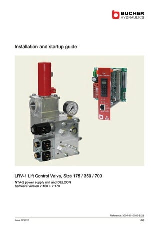
1. LRV-1 Lift Control Valve, Size 175 / 350 / 700
NTA-2 power supply unit and DELCON
Software version 2.160 + 2.170
Installation and startup guide
1/86
Reference: 300-I-9010050-E-28
Issue: 02.2012
2. LRV-1 lift control valve
2/86 300-I-9010050-E-28/02.2012
Publisher
Bucher Hydraulics AG
Industriestrasse 15
CH-6345 Neuheim
Phone +41 41 757 03 33
Fax +41 41 757 05 00
Emailinfo.nh@bucherhydraulics.com
Internet www.bucherhydraulics.com
E 2012 by Bucher Hydraulics AG, CH-6345 Neuheim
All rights reserved. This documentation, in whole and/or in part, is protected by copyright. It may
not be reproduced, nor may it be stored, processed, replicated or distributed by electronic means,
without written permission from Bucher Hydraulics.
Data is provided for the purpose of product description only, and must not be construed as war
ranted characteristics in the legal sense. No assertion regarding either a particular property or the
fitness for a particular intended purpose can be derived or deduced from this information. The in
formation does not relieve users from the duty of conducting their own evaluations and tests.
Because the products are subject to continual improvement, we reserve the right to amend the
product specifications contained in this catalogue. The original language and legal terminology of
all Bucher Hydraulics documentation is exclusively German. Bucher Hydraulics cannot be held
liable for any possible errors in translation.
5. LRV-1 lift control valve 1 General, product description
5/86300-I-9010050-E-28/02.2012
1 General, product description
This guide is an integral part of the product. It describes the product’s
safe use in all phases of operation and is valid for all model series that
are referred to.
1.1 Target group
S Operator
S Installer
S Service engineer
S Repair technician
1.2 Supplementary documents
Description Document
Lift Control Valve, Quick-Start Guide 300-P-9010169
1.3 Specialist terms
Term Definition
DELCON Electronic control card for LRV‐1 valve
6. LRV-1 lift control valve1 General, product description
6/86 300-I-9010050-E-28/02.2012
1.4 Important notes
1.4.1 Subassemblies
This guide differentiates between the following subassemblies:
LRV‐1 lift control valve
DELCON electronic control card
on NTA-2
NTA-2 power supply unit
1.4.2 Intended use
Lift control valve for operating hydraulically-driven passenger and goods
lifts.
The products must not be handled in any way by unauthorised persons.
7. LRV-1 lift control valve 1 General, product description
7/86300-I-9010050-E-28/02.2012
1.4.3 Conformity
The product was designed and developed in conformity with the
following directives and standards:
EC-directive 95/16/CE
Standards EN 81-2:1998
EMC standards EN 12015:2004
EN 12016:2004+A1:2008
8. LRV-1 lift control valve1 General, product description
8/86 300-I-9010050-E-28/02.2012
1.5 Product identification
1.5.1 Nameplate
1 2
6 7 8
9
3 4
5
LRV175-1 R175/K251/VN
120 / 150 l/min 21 / 45 bar
P min-max/adj 7-63 / 55 bar
...
10
11
1 Valve type = LRV 175
2 Flow ring = R 175
3 Spool = K 251
4 Manual emergency-lowering valve with
preload = VN
5 Flow rate UP = 120 l/min
6 Flow rate DOWN = 150 l/min
7 Minimum static pressure (empty car)
= 21 bar
8 Maximum static pressure (full car)
= 45 bar
9 Setting range = 7 … 63 bar
10 Set for maximum working pressure
= 55 bar
11 Customer specific data
1.5.2 Test number
2
1
Legend 1
2
Test number
Nameplate
9. LRV-1 lift control valve 1 General, product description
9/86300-I-9010050-E-28/02.2012
1.5.3 Model code
D0/MP/EN00/VNK 251 /-LRV 175-1 /
Valve type/size
= LRV 175-1
= LRV 350-1
= LRV 700-1
Flow range: flow rate/type
LRV 175-1 15 … 45 l/min = R 45
46 … 90 l/min = R 90
91 … 175 l/min = R 175
176 … 250 l/min = R 250
LRV 350-1 150 … 250 l/min = R 250
251 … 350 l/min = R 350
351 … 500 l/min = R 500
LRV 700-1 400 … 700 l/min = R 700
701 … 1000 l/min = R 1000
Spool: flow rate/type
LRV 175-1 15 … 90 l/min = K 91
91 … 250 l/min = K 251
LRV 350-1 150 … 500 l/min = K 501
LRV 700-1 400 … 1000 l/min = K 1001
Manual emergency-lowering valve
Emergency-lowering valve with preload = VN
Emergency-lowering valve without preload = SN
Electrical emergency-lowering valve
without electrical emergency-lowering valve = EN 00
with DC solenoid 12 V = EN 12
with DC solenoid 24 V = EN 24*
* further option: via NTA‐2 with 2x24 V batteries,
⇒ page 29, chapter 1.8.3 and page 47, chapter 4.2.4
Test port
without test nipple (female thread G½”) = OP
with test nipple (DIN 16271) = MP
DELCON type
without DELCON = D0
with DELCON = D1
R 175
10. LRV-1 lift control valve1 General, product description
10/86 300-I-9010050-E-28/02.2012
1.6 LRV‐1 lift control valve
Legend 1
2
3
4
5
6
7
8
Maximum-pressure setscrew
Bypass-pressure setscrew
Lowering-speed limiter (valve
size 700 only)
Pressure-relief valve
Pilot filter
Test port, G½
Pressure gauge
Pressure gauge shut-off screw
(valve sizes 175 and 350)/
Pressure gauge shut-off valve
(valve size 700)
9
10
11
12
13
14
15
16
17
18
20
21
Air-bleed screw
Hall sensor
Main filter
Flow-rate measuring system
Emergency-lowering valve
DOWN spool
Check valve
UP spool
UP damping jet
DOWN damping jet
Pipe rupture valve
Ball valve
P
T
Z
Z1
Z2
Z3
Pump port
Tank port
Cylinder port
Pressure switch port
Pressure switch port
Hand pump port
A
B
C
D
DELCON
NTA‐2
LRV‐1
Control cabinet (customer's)
11. LRV-1 lift control valve 1 General, product description
11/86300-I-9010050-E-28/02.2012
1.6.1 Simplified hydraulic–electrical diagram
A
B
C
D
4
6
7
8
1011
12
13
14
15
16
20
21
22
23
24
M
P T
Z
Z1
Z2
Z3
K1
K2
K3
K4
K5
K6
K7
K8
25
R1
R1’
R2
R2’
M
22a
Legend 4
6
7
8
10
11
12
13
Pressure-relief valve
Test point, G½
Pressure gauge
Pressure gauge shut-off
screw/ valve
Feedback sensor
(non-contacting)
Main filter
Flow-rate measuring system
Emergency-lowering valve
14
15
16
20
21
22
22a
23
24
25
DOWN spool
Check valve
UP spool
Pipe-rupture valve
Ball valve
Elec. emergency lowering (opt.)
Speed set. elec. emerg. low.
Pressure switch
Hand pump
Relevelling (optional)
P
T
Z
Z1
Z2
Z3
Pump port
Tank port
Cylinder port
Pressure switch port
Pressure switch port
Hand pump port
R1
R2
A
B
C
D
to EN 81-2, 12.4.1/12.4.2
to EN 81-2, 12.4.1/12.4.2
DELCON
NTA‐2
LRV‐1
Control cabinet (customer's)
12. LRV-1 lift control valve1 General, product description
12/86 300-I-9010050-E-28/02.2012
1.6.2 Electrical connection diagram
GND
YE
WH
GN
BN
A
B
C
D
22
26a
26b
4 x 12 V = 48 V
2 x 24 V = 48 V
L1, L2, L3, PE
300-1.10009306
RN
RN
RN
Legend A
B
C
D
BN
GN
WH
YE
DELCON
NTA‐2
LRV‐1
Control cabinet (customer's)
brown
green
white
yellow
22
26a/b
R1
R2
Electrical emergency-lowering
12 or 24 VDC (option)
⇒ page 48, chapter 4.2.5
Electrical emergency-lowering
2 x 24 VDC
⇒ page 47, chapter 4.2.4
to EN 81-2, 12.4.1/12.4.2
to EN 81-2, 12.4.1/12.4.2
13. LRV-1 lift control valve 1 General, product description
13/86300-I-9010050-E-28/02.2012
1.6.3 Factory settings
All valves are factory-set to the values for the particular installation and
then tested.
S Pressure-relief valve set to the maximum working pressure
S Bypass pressure as per the calculated minimum static pressure
S Emergency-lowering valve set to 5 … 10 % of maximum DOWN
speed
S Mechanical zero point of the feedback sensor
1.6.4 Description of function
The lift control valve can be subdivided into 3 main functions.
1. UP section / pressure-relief valve
4
1
16
S Initial position:
UP spool (16) is open in the 0 position; pump flow goes directly to
tank
S Up travel / acceleration:
UP spool (16) is progressively closed by the electro-proportional
valve (UP solenoid); this results in smooth acceleration of the lift up
to maximum speed
S Deceleration:
UP spool (16) is progressively opened by the electro-proportional
valve (UP solenoid); this results in smooth deceleration of the lift to
standstill
S Overload:
pressure-relief valve (4) and UP spool (16) open when the maximum
working pressure set with screw (1) is reached
14. LRV-1 lift control valve1 General, product description
14/86 300-I-9010050-E-28/02.2012
2. DOWN section / Emergency-lowering valve
13
14
The down section is constructed in a similar way to the up section.
S Initial position:
DOWN spool (14) is closed leak-free in the 0 position
S Down travel / acceleration:
DOWN spool (14) is progressively opened by the electro-proportional
valve (DOWN solenoid); this results in smooth acceleration
S Deceleration:
DOWN spool (14) is progressively closed by the electro-proportional
valve (DOWN solenoid); this results in smooth deceleration of the lift
to standstill
S Power failure/ evacuation:
With the electrical emergency-lowering valve (optional), the car can
be lowered using DC voltage (⇒ page 48, chapter 4.2.5)
S The car can be lowered slowly with the manual emergency-lowering
valve (13)
15. LRV-1 lift control valve 1 General, product description
15/86300-I-9010050-E-28/02.2012
3. Flow-rate measuring system
10
12
S The oil flows through the flow meter (12) in both the up and down
directions
S The baffle-disc is displaced axially as a function of the flow rate
S This axial displacement is converted by a non-contacting feedback
transducer (10) into an electrical DC signal (the feedback signal),
which is then sent to the DELCON.
S The output signal (the feedback) is proportional to the flow rate
S The controller in the DELCON works to match the feedback value to
the demand signal
16. LRV-1 lift control valve1 General, product description
16/86 300-I-9010050-E-28/02.2012
1.6.5 Technical data
300-7-10015573
H*
R*
L*
a
A
Legend
View: valve sizes 175 and
350
1
2
3
4
Flow-rate measuring system
Pressure-relief valve
DOWN solenoid
UP solenoid
5
6
7
a
Orientation of Z-port
Pressure gauge shut-off screw
(valve sizes 175 and 350)/
Pressure gauge shut-off valve
(valve size 700)
Test number (embossed)
View from below
Z1
Z2
Z3
P
T
Z
Pressure switch port
Pressure switch port
Hand pump port
Pump port
Tank port
Cylinder port
H*
L*
R*
Orientation of Z-port
(specify when ordering!)
rear (standard)
left
right
17. LRV-1 lift control valve 1 General, product description
17/86300-I-9010050-E-28/02.2012
Type Ports Ports Weight Max. press.
Z, T, P Z1, Z2, Z3 [kg] [bar]
LRV 175-1 G1 G¼ 8 80
LRV 350-1 G1½ G¼ 11 80
LRV 700-1 G2, G2½, G2 G¼, G¼, G3/8 22.5 67
Type Dimensions [mm]
b c d e k L m n p1 p2 s1 s2 t v1 v2
LRV 175-1 199 325 182 208 50 47 55 175 21 27 75 15 M8 9 23
LRV 350-1 219 355 205 208 65 48 63 200 35 38 85 25 M10 14 28
LRV 700-1 297 428 255 225 80 87 83 265 48 56 124 41 M10 30 30
S The permissible temperature range is determined by the permissible
viscosity range of 20 … 500 cSt.
S Independent of the viscosity the temperature must not fall below 0 °C
and must not exceed 70 °C.
S For detailed information, ⇒ page 83, chapter 6.2
18. LRV-1 lift control valve1 General, product description
18/86 300-I-9010050-E-28/02.2012
1.6.6 Pressure drop
R 90 R 175 R 250R 45
15
12.5
10
7.5
5
2.5
20
50
90
100
180
250
200
150
Spool K 91
Spool K 251
A
B
UP (P-Z)
DOWN (Z-T)
LRV 175-1
Flow ring (R)
R 350 R 500R 250
15
12.5
10
7.5
5
2.5
150
175
200
225
250
275
300
325
350
375
400
425
450
475
500
Flow ring (R)
LRV 350-1
Spool K 501A
B
DOWN (Z-T)
UP (P-Z)
Legend A
B
Pressure drop [bar] min. required dynamic pressure
Flow rate Q [l/min.]
500 cSt (Motorex Corex HLP 46 at approx. 2 °C)
300 cSt (Motorex Corex HLP 46 at approx. 7.5 °C)
75 cSt (Motorex Corex HLP 46 at approx. 30 °C)
19. LRV-1 lift control valve 1 General, product description
19/86300-I-9010050-E-28/02.2012
R 1000R 700
15
12.5
10
7.5
5
2.5
400
450
500
550
600
650
700
750
800
850
900
950
1000
LRV 700-1
A
B
Spool K 1001
Flow ring (R)
DOWN (Z-T)
UP (P-Z)
Legend A
B
Pressure drop [bar] min. required dynamic pressure
Flow rate Q [l/min.]
500 cSt (Motorex Corex HLP 46 at approx. 2 °C)
300 cSt (Motorex Corex HLP 46 at approx. 7.5 °C)
75 cSt (Motorex Corex HLP 46 at approx. 30 °C)
20. LRV-1 lift control valve1 General, product description
20/86 300-I-9010050-E-28/02.2012
1.7 DELCON electronic card
The DELCON controls the oil flow - and therefore the lift's travel profile -
in accordance with a preset curve.
NOTICE!
Electrostatic discharge (ESD)
The DELCON can be damaged by incorrect handling.
Always keep the DELCON in its ESD protective bag and
only hold it by the front panel.
6
1
2
3
5 4
7
Legend 1
2
3
4
5
6
7
RESET button (restarts the program in the
DELCON electronic card)
Nameplate
Label with serial number
Description of LED functions
RS-232 port
LED
Label with test number and demand values
1.7.1 Factory settings
S Maximum UP and DOWN speeds
S Slow speed set to 5 … 10 % of maximum speed
S Acceleration/deceleration set to mid-range value
S Inspection travel speed set to 50 % of maximum speed
21. LRV-1 lift control valve 1 General, product description
21/86300-I-9010050-E-28/02.2012
1.7.2 Description of function
S The lift control system sends the command signals to the DELCON
via potential-free relay contacts or semiconductors.
S The feedback value is compared with the demand travel curve and
controlled throughout the whole travel.
S Deviations from the demand curve are corrected by the UP and
DOWN proportional solenoids.
S The closed-loop control ensures that the travel characteristics are
independent of load and temperature.
S The inspection speed can be set through command K5 of the lift
control system (there is no monitoring of maximum permissible
demand/feedback deviation during travel at inspection speed!)
S Reduced speeds for short travel distances are also possible via
command signals K6 … K8.
S The DELCON enables soft-stopping (gentle halt) with very accurate
positioning (±3 mm).
Features
S The travel curve for the up and down directions is set and adjusted
with the Miniterminal, the Handterminal or a PC.
S The demand curve can be set and checked at the DELCON while the
lift is at standstill.
S Measured values can be checked with the Handterminal.
S The DELCON card is easy to exchange (1 card for all valves), which
means that rapid fault-fixing is ensured.
Note: If the DELCON is exchanged, the installation-specific parameters
must be replicated in the new card.
22. LRV-1 lift control valve1 General, product description
22/86 300-I-9010050-E-28/02.2012
1.7.3 Technical data
Weight: 130 g
300-2-10002640
160 30.5
128.5
100
General description
S Digital electronic card for the LRV‐1 valve
S Enhanced ride comfort
S Automatic reduction of demand signal if nominal speed is not
attained
S Extended functions
S Simple set-up
S Easy to trouble-shoot
New installations
S Factory settings permanently stored
Replacement cards
S Contain basic settings.
For installation-specific settings, ⇒ page 63, chapter 5
23. LRV-1 lift control valve 1 General, product description
23/86300-I-9010050-E-28/02.2012
1.7.4 Travel and switching diagram for normal travel distance
**
*Y−
N
* Motor run-on time of 0.5 … 1 s
** Drop-out delay of 0.5 … 1 s, after drop
out of K4
Y-Δ Y starting time of up to approx.
3 s with Y-Δ,
K1 and K2 not until Δ connection
Legend 1
2
3
4
Motor contactor ON
Safety relay R2 closed
K2 ”Slow UP” is present
K1 ”Fast UP” is present
5
6
7
K3 ”Fast DOWN” is present
K4 ”Slow DOWN” is present
Safety relay R1 closed
N Normal distance between floors
24. LRV-1 lift control valve1 General, product description
24/86 300-I-9010050-E-28/02.2012
1.7.5 Travel and switching diagram for short travel distances
The electronics of the LRV‐1 valve make it possible to control stops at
mezzanines and similar short travel distances with the same ride
comfort as in normal travel.
Note: The maximum speed should be reduced to a value that, despite
the short travel distance, can actually be attained.
Short distance between floors with normal speed
(slow-speed travel distance too long)
Short distance between floors with reduced speed
(K6)
N
K
N
K
ZX
ZY
ZY
XZ
Y**
**
*
**
***
V
Motor run-on time of 0.5 … 1 s
Drop-out delay of 0.5 … 1 s, after drop out of K4
+ K6
K1 and K2 not until Δ connection
Adjust the speed to suit the circumstances (e.g.
50 %)
X
Y
Z
Deceleration switch at normal speed
Deceleration switch at reduced speed
Soft-Stop is not separately adjustable
Legend 1
2
3
4
Motor contactor ON
Safety relay R2 closed
K2 + K6 are present
K1 is present
5
6
7
K3 is present
K4 + K6 are present
Safety relay R1 closed
N Normal distance between floors K Short distance between floors
S By using command signals K6, K7 or K8, various reductions in the
nominal speed can be achieved (e.g. for different floor spacings).
S The speed reduction can be adjusted between 20 … 100 % of
nominal speed
25. LRV-1 lift control valve 1 General, product description
25/86300-I-9010050-E-28/02.2012
S Speed can be set by means of parameter ”K6 speed” (or ”K7 speed” /
”K8 speed”) in the Options menu to match the floor spacing (distance
between stops).
S Acceleration can be adjusted separately via parameters ”K6
acceleration” (or ”K7 acceleration” / ”K8 acceleration”) in the Options
menu.
S Deceleration can be adjusted separately via parameters ”K6
deceleration” (or ”K7 deceleration” / ”K8 deceleration”) in the Options
menu.
1.8 NTA‐2 power supply unit
The NTA‐2 power supply unit provides both power supply and physical
support for the DELCON.
300-1-10008856
Legend 1
2
3
4
5
Mains voltage terminals
Socket for feedback cable
Terminal block
(screwless)
Jumper JP2 (connects Earth
and Signal GND)
Terminal block for SIU
connection
6
7
8
9
Terminal block for emergency
power supply
Jumper JP1 (inversion of relay
function)
Transformer
Card-holder for DELCON
1.8.1 Description
The power supply unit is connected directly to the main supply.
The control signals for the DELCON are connected to the terminal block
(3).
Through the terminals 18–17a (N.O. make contact)
18–17b (N.C. break contact)
a relay output is provided.
Its function is defined in the DELCON by the settings of the ”SIU type”
and ”Relay function” parameters.
26. LRV-1 lift control valve1 General, product description
26/86 300-I-9010050-E-28/02.2012
Parameter “SIU type”
1 SIU-1: relay switches when the demand/feedback
difference is exceeded (there is no SIU-1 monitoring
during inspection speed with K5!).
1 + 4 SIU-1 (functions as above) and SIU-4: relay switches
when the speed set with the parameter “SIU-4 threshold”
is exceeded.
Parameter ”Relay function”
only SIU1 The relay on the power supply unit switches only when
there is an SIU-1 fault.
all errors The relay on the power supply unit switches with any
fault.
only SIU4 The relay on the power supply unit switches only when
there is an SIU-4 fault.
For a detailed overview of the combined effects of the parameters “SIU
type and “Relay function”, ⇒ table on page 70
JP1 selects the relay's passive state:
1-2 Current flows through the relay in its passive state (no
current when function is activated)
2-3 No current through the relay in its passive state (current
flows when function is activated)
Feeding of the power
supply unit
Use of relay terminals Setting JP1
Permanent feeding 17a, 18 1-2
Power supply unit
operatated in safety
circuit*
17b, 18 2-3
*Note: Operating the power supply unit in the safety circuit allows the
omission of the safety relays R1 and R2, however, it involves the
following disadvantages:
S The frequent powering up and down reduces the service life of the
DELCON electronic card.
S To set the mechanical zero point, the safety circuit must be closed
in order that the power supply unit is powered.
S The soft-stop may not function correctly if input voltage is switched
off immediately.
S After closing the safety circuit a command signal K1 … K8 can be
applied only after a 0.5 seconds delay.
S Delays of up to 2 s may occur until the lift starts.
Bucher Hydraulics therefore discourages the operation of the power
supply unit in the safety circuit.
27. LRV-1 lift control valve 1 General, product description
27/86300-I-9010050-E-28/02.2012
The jumper JP2 connects the terminals 12 of the command signal
terminal strip to the terminal PE of the mains voltage connection,
earthing the reference potential of the command inputs (standard
setting).
NOTICE!
Earth loop
Earth loops can cause malfunctions.
With the jumper JP2 set the reference potential of the
command input must not be earthed a second time on the
side of the lift control.
If the reference potential of the command inputs cannot be
insulated from earth on the side of the lift control, the
jumper JP2 must be removed.
NOTICE!
Damage to the electronic card DELCON
Connecting the NTA‐2 to the mains WITHOUT a DELCON
inserted will persistently charge capacitors on the NTA‐2.
Inserting the DELCON onto a NTA‐2 whose capacitors are
charged can damage the DELCON.
A NTA‐2 without a DELCON inserted must NOT be
connected to the mains at any time.
28. LRV-1 lift control valve1 General, product description
28/86 300-I-9010050-E-28/02.2012
1.8.2 Technical data
300-1-10008856
110
100
100
110
M4
8 12 151.7
Weight 0.675 kg
Mains voltage NTA‐2/115 100/(110)115/120 VAC ±10 %
NTA‐2/230 220/230/240 VAC ±10 %
NTA‐2/400 380/400(415)/440 VAC ±10 %
Frequency 50/60 Hz ±10 %
Power consumption 20 W during travel,
approx. 8 W at standstill
EMC standards EN 12015, EN 12016
Protection class IP 00
Relay contacts lmin = 10 mA
lmax = 3 A (230 VAC)
3 A (30 VDC)
0.3 A (100 VDC)
Command inputs
Command present U < 2.5 V
Command current ≈ 6 mA
Command not present U > 10 V
29. LRV-1 lift control valve 1 General, product description
29/86300-I-9010050-E-28/02.2012
1.8.3 Terminal assignments
1
2
3
4
5
21
22
23
12
12
6a
7
6b
8
L1c/L2c
9
10
11
12
L1b/L2b
L1a/L2a
PE
N/L1
17a
17b
18
19
12
20
A B
C
D
E
JP1
JP2
Legend A
B
C
Control signals
Connection for feedback cable
Mains voltage connection
D
E
Demand / feedback monitoring
Emergency power supply
Terminal Description
Mains Voltage Connection
NTA‐2/115 NTA‐2/230 NTA‐2/400
N/L1 Neutral (N) Neutral (N) Phase (L1)
L1a/L2a*
L1b/L2b*
L1c/L2c*
Phase (L1): 120 V
Phase (L1): (110)/115 V
Phase (L1): 100 V
Phase (L1): 240 V
Phase (L1): 230 V
Phase (L1): 220 V
Phase (L2): 440 V
Phase (L2): 400/(415) V
Phase (L2): 380 V
*connect only one of the 3 terminals
PE Earth conductor
30. LRV-1 lift control valve1 General, product description
30/86 300-I-9010050-E-28/02.2012
Terminal Description
Command signals (with setting command input to “Bucher K1..K8”)
1
2
3
4
5
21
22
23
12
12
6a
7
6b
8
K1 Fast UP
K2 Slow UP
K3 Fast DOWN
K4 Slow DOWN
K5 Inspection speed
K6 Speed reduction (auxiliary speed)
K7 Speed reduction (auxiliary speed)
K8 Speed reduction (auxiliary speed)
Ground/reference potential (GND) for command inputs (K1 … K8)
Ground/reference potential (GND) for command inputs (K1 … K8)
Common, DOWN solenoid
Output, DOWN solenoid
Common, UP solenoid
Output, UP solenoid
Demand / feedback monitoring
17a
18
17b
Relay output for the monitoring of the demand/feedback deviation (SIU-1) or the
speed in the unlocking zone (SIU-4).
⇒ page 25, chapter 1.8.1 and table on page 70
Connection for feedback cable
9
10
11
12
Stabilised voltage supply +15 V
Feedback signal (input)
Stabilised voltage supply –15 V
Ground, Hall sensor (GND)
Emergency power supply
19
12
20
+24 V emergency power supply
Ground, emergency power supply (GND)
–24 V emergency power supply
31. LRV-1 lift control valve 1 General, product description
31/86300-I-9010050-E-28/02.2012
1.9 IWK-1 feedback cable
Note: The feedback cable must be run from the lift control valve directly
to the NTA‐2 power supply unit without any intermediate terminals. Any
discontinuity in the feedback cable (break, kink, etc.) can endanger
trouble-free operation.
It is essential that connection 2 is ground-bonded to terminal 12,
otherwise the zero point of the sensor will not be stable.
If you cut the cable to length and terminate it yourself, be sure to wire it
correctly in accordance with the following diagram:
BN
GN
WH
YE
Legend A
B
C
D
Line socket with PG7 gland
NTA-2 connector
WAGO plug
Screen
E
F
G
H
Supply +15 V
Signal 0 … ±13.4 V
Supply –15 V
Ground
Colours BN
GN
brown
green
WH
YE
white
yellow
1.10 Surroundings
For reliable operation, the following conditions must be maintained in
the surroundings:
Surroundings Requirement
Machine room
temperature
2 … 40 ° C
Oil temperature 0 … 70 ° C*
Relative air humidity max. 90 % (non-condensing)
* The permissible temperature range is determined by the permissible
viscosity range. For detailed information, ⇒ page 83, chapter 6.2.
1.11 Emissions
The following emissions can occur during operation:
Emission Corrective action / Note
Heat Ensure fresh-air supply and warm-air extraction
Noise Sound-proof the entrance to lift shaft (noise transmission)
32. LRV-1 lift control valve2 Safety instructions
32/86 300-I-9010050-E-28/02.2012
2 Safety instructions
This documentation (manual) advises the user of the dangers and re
maining risks that can arise even when the product is being used
properly and for its intended purpose. It is essential to take note of the
safety instructions in each section.
Signal words Meaning
DANGER! This denotes a directly imminent danger. If it is
not attended to, it will result in death or serious in
juries to people.
WARNING! Denotes a potentially dangerous situation. If it is
not prevented, it may result in death or serious in
juries to people.
CAUTION! Denotes a potentially dangerous situation. If it is
not prevented, it may result in slight or minor inju
ries to people.
NOTICE! Denotes a potentially harmful situation. If it is not
prevented, the product or its surroundings may
be damaged.
33. LRV-1 lift control valve 3 Operating controls and indicators
33/86300-I-9010050-E-28/02.2012
3 Operating controls and indicators
14
8
13
18
3
12
11
10
9
17
2
1
300-7-10012261_iso_C-LRV
Illustration shows valve size 350, valve size 700 varies
Item Description Tools
1 Maximum-pressure setscrew 2 x open-ended spanner, 13 mm A/F
2 Bypass-pressure setscrew Open-ended spanner, 10 mm A/F
Allen key, 5 mm A/F
3 Lowering-speed limiter (valve size 700 only) Open-ended spanner, 10 mm A/F
Allen key, 5 mm A/F
8 Pressure gauge shut-off screw (valve sizes 175
and 350)/
Pressure gauge shut-off valve (valve size 700)
Allen key, 4 mm A/F
—
9 Filter screw, UP Open-ended spanner, 22 mm A/F
10 UP solenoid Allen key, 3 mm A/F
11 DOWN solenoid Allen key, 3 mm A/F
12 Filter screw, DOWN Open-ended spanner, 22 mm A/F
13 Pilot plate Allen key, 6 mm A/F
14 Adjusting/clamp screw for mech. zero point / Hall
sensor
Allen key, 3 mm A/F
17 UP damping jet* Allen key, 3 mm / 5 mm A/F
18 DOWN damping jet* Allen key, 3 mm / 5 mm A/F
* Accessible from the front side only for valve size 700; valve sizes 175 and 350 require removal of the pilot plate
34. 1
LRV-1 lift control valve3 Operating controls and indicators
34/86 300-I-9010050-E-28/02.2012
3.1 Emergency-lowering valve (EN 81.2 art. 12.9)
DANGER!
Car descent
Leads to death or serious injuries.
Before operating the emergency-lowering valve, make
sure that there are no people or materials in the lift shaft.
Pressing lever = lowering the car
The car is lowered by pressing the lever of the emergency-lowering
valve.
Type VN:
Note: The minimum preload pressure of 6 … 10 bar remains (prevents
slack-rope build-up as per EN 81-2, art. 12.9.1.5).
Temporary deactivation of preload pressure
For the purpose of checks or maintenance the preload can be
temporarily deactivated.
If no other M3-screw is ready to hand:
1. Remove the fastening screw from a solenoid plug
2. Screw the M3-screw into the opening (1) of the lever of the
emergency-lowering valve
In order to deactivate the preload pressure:
3. Pull the M3-screw and simultaneously press the lever of the
emergency-lowering valve
4. Undo the M3-screw from the lever of the emergency lowering
If the M3-screw had been undone from the solenoid plug:
5. Screw the M3-screw back into the solenoid plug
35. LRV-1 lift control valve
35/86300-I-9010050-E-28/02.2012
3.2 Display of the operating status
Legend for the LEDs
1 RUN
Ready for operation (green). Lights when ready for travel; off during
parameterisation
2 UP
UP travel (yellow). Lights during upwards travel (fast and slow)
3 DOWN
DOWN travel (yellow). Lights during downwards travel (fast and slow)
4 ERROR
Fault indication (red). Lights when a fault has occurred; no travel is
possible
5 SIU-1
SIU-1 display (yellow). Lights when the permissible demand/feedback
difference is exceeded
6 RELAY
Relay display (yellow). Lights when the relay on power supply unit
actuates because of a fault, ⇒ table on page 70
3.3 Miniterminal
Keys
1 Demand values menu
2 Options menu
3 Zero point display
4 Menu - Information
↑ Steps to previous parameter
↓ Steps to next parameter
+ Increases the value of the
current parameter
- Decreases the value of the
current parameter
E When parameter value is displayed:
back to parameter selection;
in parameter selection mode:
quits parameterisation mode
↵ Pipe-rupture valve test
General description
S Commands are displayed during travel
S Zero-point adjustment
S Fault memory can be called up
Operating controls and indicators
36. LRV-1 lift control valve
36/86 300-I-9010050-E-28/02.2012
Display during travel
During travel the display indicates the status of the command inputs
K1 … K8.
For this purpose the command signals are displayed coded as powers
of 2:
S K1 = 1
S K2 = 2
S K3 = 4
S K4 = 8
S K5 = 16
S K6 = 32
S K7 = 64
S K8 = 128
If several command signals are present simultaneously, e.g. K3 and K4,
the display indicates the sum of the individual signals:
K3 = 4, K4 = 8, display = 012
With the command input set to Bucher K1..K8 (⇒ page 71) the following
values will be displayed:
Travel
command
Command
signal
Additional command signals
none
(normal
travel)
Inspection
speed
Auxiliary speed
— K5 K6 K7 K8
none 0 16 32 64 128
Slow UP K2 2 18 34 66 130
Fast UP K1 + K2 3 19 35 67 131
Slow DOWN K4 8 24 40 72 136
Fast DOWN K3 + K4 12 28 44 76 140
Description of function
S By pressing any of the keys 1 to 4 for at least 2 seconds, the
DELCON switches into parameterisation mode. No travel is possible;
the green RUN LED on the DELCON goes out.
S Select the desired parameter using the ↑ or ↓ key
Note: The parameter names of the menu Options (2) do not appear in
numeric order of sequence, but in the order of sequence as shown in the
parameter overview, ⇒ page 64, chapter 5.2
S Display value with + or – key
S Increase value with + key, decrease value with – key
S With ↑ or ↓ key, save the value and return to parameter selection
S With key E, do not save the value and return to parameterisation
mode
S Press the key E again to quit parameterisation mode
Operating controls and indicators
37. LRV-1 lift control valve
37/86300-I-9010050-E-28/02.2012
S If no key pressed within 5 minutes, the DELCON automatically quits
parameterisation mode (changes to the currently displayed
parameter are not saved).
Display during parameterisation
S Parameter name e.g. P1.01 = Start speed UP
S P1.xx: Demand value parameters
S P2.xx: Options parameters
S d4.xx: Informations
S F4.xx: Error list
S Overview of parameters accessible with the Miniterminal ⇒ page 64,
chapter 5.2
S Display of value of parameter, excluding name of unit, e.g. 6.85
Fault code
S Fault memory for the last 8 faults
S For explanation of error codes ⇒ page 78, chapter 5.7.2
Example for changing parameter value
Change parameter value “Inspection" (P2.06)
1. Press key 2 for approximately 2 seconds
⇒ DELCON switches to the parameterisation mode
⇒ green LED (RUN) on DELCON goes out
⇒ travel not possible
2. With the ↑ or ↓ key, select the parameter with display P2.06
⇒ ↑ to switch to previous parameter display
⇒ ↓ switch to next parameter display
3. Press key + or – once
⇒ the actual parameter value is displayed
4. Press key + or – again until the desired numerical value is reached
⇒ + parameter value is increased
⇒ – parameter value is decreased
5. Press key ↑ or ↓
⇒ save desired parameter value
⇒ return to parameter display P2.06
I Note: With the E key, value changes NOT saved
and return to last parameter display P2.06
6. With key ↑ or ↓, select the next parameter
or
with keys 1 ... 4, select a different menu
7. Quit parameterisation mode with the E key
⇒ green LED (RUN) on DELCON lights up
⇒ travel possible
Operating controls and indicators
38. LRV-1 lift control valve
38/86 300-I-9010050-E-28/02.2012
3.4 Handterminal
Keys
1 Demand values menu
2 Options menu
3 Zero point display
4 Information menu
↑ Steps to previous parameter
↓ Steps to next parameter
+ Increases the value of the
current parameter
- Decreases the value of the
current parameter
General description
S Easy set-up of the travel curve
S Commands, feedback value and control voltage are displayed during
travel
S Zero-point adjustment
S Fault memory can be called up
Connection
S Connect the Handterminal to the DELCON using the cable provided
S Connecting cable is standard Ethernet network cable
Description of function
S By pressing any of the keys 1 to 4, the DELCON switches into
parameterisation mode. No travel is possible; the green RUN LED on
the DELCON goes out.
S Select the desired parameter using the ↑ or ↓ key
S Increase value with + key, decrease value with – key
S With ↑ or ↓ key, save the value and return to parameter selection
S With keys 1, 2, 3 or 4, do not save the value and return to
parameterisation mode
S If no key pressed within 5 minutes, the DELCON automatically quits
parameterisation mode (changes to the currently displayed
parameter are not saved).
Operating controls and indicators
39. LRV-1 lift control valve
39/86300-I-9010050-E-28/02.2012
Note: In order to quit parameterisation mode:
S Either press keys ↑ and ↓ simultaneously (changes to the currently
displayed parameter are saved)
or
S unplug cable and wait for about 3 seconds (changes to the
currently displayed parameter are NOT saved)
DELCON will return to RUN mode.
e.g.
K1-K8 1100 0000
C: +3.45 F: +4.18
Display during travel
S 1st line: status of command inputs K1 … K8
0: no command
1: command is present
S 2nd line: existing control voltage (C) and
feedback value (F) in volts
e.g.
Fast speed ^
7.50 V
Display during parameterisation
S 1st line: parameter name
S 2nd line: value of parameter, including unit
e.g.
1) Err:SIU-1
1x 51965 h
Fault code
S 1st line: fault memory read-out, fault
description
S 2nd line:total number of occurrences of this
fault; last occurrence was at operating
hours h
S For explanation of error codes ⇒ page 78,
chapter 5.7.2
3.5 Password
The DELCON's parameters and functions can be password-protected.
The password consists of four digits. Password “0000" means that
password protection is not activated (this is the factory setting).
Setting a password
1. Press the key 4
The display will read Commands
Information list
.
2. Press the key ↑ several times until the display reads
Password
+ execute
3. Press the key +
Operating controls and indicators
40. LRV-1 lift control valve
40/86 300-I-9010050-E-28/02.2012
If either no password has previously been set (i.e. password is “0000"),
or a password is set and the user is currently logged in the display will
read + change
– log out
.
Continue with step 4
If the display reads + log in
– show code
a password has already been set.
The user is currently not logged in.
Abort by pressing the keys ↑ and ↓ simultaneously
In order to continue setting a password:
4. Press the key +
The display will read Password
0000
with the first digit signaling.
5. Press the key + to increase
or
the key – to decrease the value of the signaling digit
6. Press the key ↓ to select the next digit
or
the key ↑ to select the previous digit
When all digits display the desired value, with the digit currently selected
still signaling:
7. Press the keys ↑ and ↓ simultaneously to transmit the password
The display will read Confirmation
0000
with the first digit signaling. The
user is prompted to enter the password a second time for confirmation.
8. Enter the password again as described above, finish by pressing
the keys ↑ and ↓ simultaneously
If the two passwords entered are identical, the DELCON will quit para
meterisation mode.
The user is logged in, parameters can be changed.
In order to log out and protect the DELCON against inadvertent para
meterisation: ⇒ Logging out
If the two passwords entered are different, the display will read
Confirmation
not allowed
for approx. 1 second, then change to
Password
0000
with the first digit signaling. The user is prompted to
repeat the complete password setting procedure.
Logging in
1. Press the key 4
The display will read Commands
Information list
.
Operating controls and indicators
41. LRV-1 lift control valve
41/86300-I-9010050-E-28/02.2012
2. Press the key ↑ several times until the display reads
Password
+ execute
3. Press the key +
If the display reads + change
– log out
the user is either logged in
already, or no password is set (i.e. password is “0000").
Press one of the keys 1 to 4 to continue in parameterisation mode or
press the keys ↑ and ↓ simultaneously to quit parameterisation mode
If the display reads + log in
– show code
a password is set and the user is
currently not logged in.
Continue with step 4
4. Press the key +
The display will read Password
0000
with the first digit signaling.
5. Press the key + to increase or the key – to decrease the value of
the signaling digit
6. Press the key ↓ to select the next digit
or
the key ↑ to select the previous digit
When all digits display the desired value, with the digit currently selected
still signaling:
7. Press the keys ↑ and ↓ simultaneously to transmit the password
If the password entered is correct, the DELCON will quit parameterisa
tion mode.
The user is logged in, parameters can be changed.
If the password entered is incorrect, the display will read
Password
not allowed
for approx. 1 second, then the DELCON will quit para
meterisation mode.
In order to try again, start over pressing key 4
In order to retrieve a forgotten password: ⇒ Forgotten password
Logging out
Note: The DELCON features a counter, that logs out the user
automatically after 8 hours. The proper function of the counter requires,
however, that the power supply to the DELCON will NOT be disrupted.
Disruption of the power supply causes the counter to start over, while
keeping the user logged in.
In order to log out manually:
1. Press the key 4
Operating controls and indicators
42. LRV-1 lift control valve
42/86 300-I-9010050-E-28/02.2012
The display will read Commands
Information list
.
2. Press the key ↑ several times until the display reads
Password
+ execute
3. Press the key +
The display will read + change
– log out
.
4. Press the key –
The DELCON will quit parameterisation mode.
If an attempt is made to change a parameter while the user is logged
out, the display will read parameter name
not allowed
^ .
Abort by pressing the keys ↑ and ↓ simultaneously
Forgotten password
1. Press the key 4
The display will read Commands
Information list
.
2. Press the key ↑ several times until the display reads
Password
+ execute
3. Press the key +
If the display reads + change
– log out
the user is either logged in
already, or no password is set (i.e. password is “0000").
Abort by pressing the keys ↑ and ↓ simultaneously
If the display reads + log in
– show code
a password is set and the user is
currently not logged in.
Continue with step 4
4. Press the key –
The display will read Code
code number
.
5. Report the code number to the Bucher customer service in order to
obtain the valid password
Die
6. Log in with the valid password: ⇒ Logging in
or
abort by pressing the keys ↑ and ↓ simultaneously
Operating controls and indicators
43. LRV-1 lift control valve
43/86300-I-9010050-E-28/02.2012
3.6 WinDelta32 - PC program
Software, RS232-adapter and cable can be ordered as part no.
3007010867+
RS232-USB converter can be ordered as part no. 3007014722
The software can be downloaded free of charge from:
http://www.bucherhydraulics.com
Parameterisation
S DELCON parameters can be read off and set via PC
S Parameter sets can be saved
S Comments can be added to parameter sets
S Print function
Display of curves
S Curves (demand signal / feedback value / control voltage) displayed
in real time
S Display of commands K1 … K8
S Zoom function / Print function
Installation and commissioning
44. LRV-1 lift control valve4 Installation and commissioning
44/86 300-I-9010050-E-28/02.2012
4 Installation and commissioning
4.1 Installation
Orientation of the ball-valve outlet
As standard, the ball-valve outlet is rear-facing (code H)
Alteration to left (L) or right (R) is possible.
Note: The ball-valve outlet must not be turned to a new position unless
the hose is first disconnected.
Reorienting the ball-valve outlet
1. Unscrew cap screws on head of valve
2. Remove the screws
NOTICE!
Risk of damage to the flow-rate measuring system
When orienting the ball-valve outlet, never lift up the head
of the valve.
3. Turn head of valve to desired ball-valve position
4. Insert the cap screws and tighten them
I Tightening torque for LRV 175-1 = 25 Nm
LRV 350-1 = 50 Nm
LRV 700-1 = 80 Nm
5. Check the mechanical zero point
I Readjustment may be necessary (⇒ page 56, chapter 4.3.9)
The ball-valve outlet is now correctly oriented
4.2 Assembly
4.2.1 Hose or pipe
CAUTION!
Contamination in the line
Contamination adversely affects the valve's function. This
can lead to a dangerous system condition.
Preventive measures:
S Clean the hose or pipe before fitting it
S Leave sealing caps/plugs in place until assembly
S Check that all fittings are assembled correctly
S Do not twist the hoses
45. Feedback cable
connection
⇒ page 31
LRV-1 lift control valve 4 Installation and commissioning
45/86300-I-9010050-E-28/02.2012
S Do not mount hoses under tensile strain
S Observe minimum bending radia
S Protect hoses against mechanical damage (e.g. from sharp edges)
S Support hoses with hose clamps (approx. 1.5 m away from valve)
4.2.2 Power supply unit
DANGER!
Dangerous voltage
Leads to death or serious injuries.
Before fitting the power supply unit, disconnect all power to
the control cabinet.
S The NTA‐2 power supply unit is intended for installation in the control
cabinet.
S There must be no voltage at the power supply unit when working on
its connections or exchanging the DELCON.
Note: Set jumper JP2 to earth the reference potential of the command
inputs (observe the note on page 27).
Screwless terminals
Note: To prevent damage, the NTA‐2 must only be wired when the
DELCON card has been removed.
Command signals Feedback cable plug
11
2
2
S Only one core per terminal point (if necessary,
combine two cores in a terminating sleeve)
S Use a size 0 screwdriver (2.5 mm)
S Insert a screwdriver (1) as far as the stop
S Open the clamp spring by gently pressing down
or turning the screwdriver, and insert the core (2)
into the terminal point
S Remove the screwdriver - the conductor is now
safely clamped
46. LRV-1 lift control valve4 Installation and commissioning
46/86 300-I-9010050-E-28/02.2012
4.2.3 Wiring the power supply unit
K1
K2
K3
K4
PE
L1N
1
2
3
4
5
21
22
23
12
12
GND
6a
7
6b
8
18
17a
17b
9
10
11
12
12
20
19
+24V +24V
PWM
0...100%
ON/OFF
JP2
-24V
+24V
N
S
GND
3 214
**
**
**
*
300-1-10009300
D
A
B
C
E
F
G
WH GN YE BN
1
2
3
4
5
21
22
23
12
6a/6b
7
8
9
10
11
12
20
19
YE
GN
BN
WH
Legend
Fast UP
Slow UP
Fast DOWN
Slow DOWN
Inspection speed
Auxiliary speed
Auxiliary speed
Auxiliary speed
Reference potential
Common
DOWN solenoid
UP solenoid
Stabilised voltage
supply +15 V
Feedback signal
(input)
Stabilised voltage
supply –15 V
GND, test/measurement
–24 V emergency power
supply
+24 V emergency power
supply
yellow
green
brown
white
* When the additional command K5 is present, the
DELCON's two ”fast” speeds drop to a preset
percentage of their nominal values. The setting is
adjustable between 20 … 80 %.
** When the additional command K6, K7 or K8 is present,
the DELCON’s two ”fast” speeds drop to a preset
percentage of their nominal values. The settings are
adjustable between 20 … 100 %.
K1 … K8, potential-free contacts or semiconductors
R1+R2 as per EN 81-2, 12.4.1/12.4.2
Legend A
B
C
D
DELCON
NTA‐2
LRV‐1
Control cabinet (customer's)
E
F
G
DOWN solenoid
UP solenoid
Relay for the monitoring of the
demand feedback deviation or
the speed in the unlocking
zone
47. LRV-1 lift control valve 4 Installation and commissioning
47/86300-I-9010050-E-28/02.2012
4.2.4 Electrical emergency-lowering 2 x 24 VDC
Note: The operator must undertake any further measures required to
ensure short-circuit and overvoltage protection.
If a mains (line) failure occurs, the power supply unit can be powered by
an external battery supply (2 x 24 V) through terminals 12, 19 and 20.
S Relay RN drops out when there is a power failure and the two
normally-closed relays connect to the battery.
I Inputs 19 and 20 have diode-protection from polarity reversal or
feedback to the battery.
S The lift can be lowered to a predefined stopping position by means of
”Slow DOWN” or auxiliary speed K6 … K8 (travel signals are
generated by the lift control system or by a push-button switch).
Note: only possible with 2 x 24 V (or 4 x 12 V) batteries
4
Slow DOWN Auxiliary speed
K6/K7/K8
21/22/23
Legend 1 NTA‐2 power supply unit
2 Supplied by customer
3 DOWN solenoid
48. LRV-1 lift control valve4 Installation and commissioning
48/86 300-I-9010050-E-28/02.2012
4.2.5 Electrical emergency-lowering 1 x 12 or 1 x 24 VDC (option)
WARNING!
Do not activate the electrical emergency-lowering valve
unless the safety circuit is closed!
In an emergency the lift car can be lowered by operating the emergency
lowering valve electrically.
Depending on the external battery voltage, 12 VDC and 24 VDC spool
valve versions are available.
Wiring diagram
12 / 24* VDC +
–
+
–
/
**
* specify when ordering ** any polarity
Setting the lowering speed
1. Energise emergency-lowering valve (22)
I The car sinks
2. Slacken the locknut of the adjusting screw (22a)
3. Turn adjusting screw counterclockwise (faster) or clockwise (slower)
4. Re-tighten locknut
Lowering speed is set
22
22a
Legend 22 Electrical emergency-lowering valve
22a Adjusting screw
49. LRV-1 lift control valve 4 Installation and commissioning
49/86300-I-9010050-E-28/02.2012
4.3 Commissioning/settings
4.3.1 Checking the test numbers
S The valve test number is stamped on the body (below the manual
pump) ⇒ page 8, chapter 1.5.2.
S DELCON test number: ⇒ page 20, chapter 1.7, item 7
Note: Always quote the test number when making enquiries. This makes
it easier for the factory to help you!
Note: The test numbers on the DELCON and the valve must be the same
to avoid the need for resetting.
4.3.2 Checking the minimum static pressure
To check the minimum static pressure (with empty car):
1. Make sure that the pressure gauge shut-off screw/ shut-off valve is
undone (the pressure gauge indicates changing pressures in the lift
system without delay)
2. Read the minimum static pressure on the pressure gauge
3. Compare minimum static pressure on rating plate with actual
minimum static system pressure on the pressure gauge
I ⇒ page 8, chapter 1.5.1, item (7)
4. If the difference is more than 5 bar, but less than 10 bar:
set the bypass pressure again (⇒ page 50, chapter 4.3.3) and
decrease or increase the maximum operating pressure resp. by the
amount of the difference (⇒ page 53, chapter 4.3.4)
I Bypass pressure too high: car travels past landing
I Bypass pressure too low: UP starting jolt
5. If the difference is more than 10 bar:
contact the customer service
The minimum static pressure shown is correct
50. LRV-1 lift control valve
50/86 300-I-9010050-E-28/02.2012
4.3.3 Bypass pressure setting
Setting the bypass pressure with the Handterminal or Miniterminal
1. Make sure that the car is empty
2. Slacken the locknut for bypass-pressure setscrew (2)
3. Unscrew bypass-pressure setscrew (2) approx. 2 turns
counterclockwise
If the Handterminal is being used:
4. Connect the Handterminal to the DELCON
5. Press key 3 on Handterminal or Miniterminal => zero point or
feedback value will be displayed, monitoring of
demand/feedback-difference (SIU-1) and speed in the unlocking
zone (SIU-4) are disabled
6. Send UP command
7. With motor running, slowly turn bypass-pressure setscrew (2)
clockwise until feedback value rises (visible on the display), until the
car moves or until the beep tone sounds
8. Turn bypass-pressure setscrew (2) back by half a turn
counterclockwise
9. Tighten the locknut for bypass-pressure setscrew (2)
10. Cancel the UP command
If the Handterminal is being used:
11. Disconnect the Handterminal from the DELCON
If the Miniterminal is being used:
12. Press the key E
13. Overwrite the value of the min. static pressure given on the
nameplate (⇒ page 8, chapter 1.5.1, Item (7)) with the actual value
The bypass pressure is now set
Installation and commissioning
51. LRV-1 lift control valve
51/86300-I-9010050-E-28/02.2012
Setting the bypass pressure with the pressure gauge, without
Handterminal
1. Make sure that the car is empty
2. Make sure that the pressure gauge shut-off screw/ shut-off valve is
undone (the pressure gauge indicates changing pressures in the lift
system without delay)
3. Read the minimum static pressure on the pressure gauge
4. Close the ball valve
5. Press emergency-lowering lever (vents pressure in the valve)
I ⇒ page 34, chapter 3.1
6. Bridge the two terminals of the relay output connected to the lift
control system (either 17a, 18 or 17b, 18 – depending on the
configuration of the relay output, ⇒ page 25, chapter 1.8.1)
7. Remove the UP solenoid plug (10)
8. Slacken the locknut for bypass-pressure setscrew (2)
9. Unscrew bypass-pressure setscrew (2) approx. 2 turns
counterclockwise
10. Send UP command
11. With motor running, slowly turn bypass-pressure setscrew (2)
clockwise until pressure is approx. 3 bar below the min. static
pressure previously read
12. Tighten the locknut for bypass-pressure setscrew (2)
13. Cancel the UP command
14. Remove the bridge from the terminals of the relay output
15. Refit the UP solenoid plug (10)
16. Open the ball valve
17. Overwrite the value of the min. static pressure given on the
nameplate (⇒ page 8, chapter 1.5.1, Item (7)) with the actual value
The bypass pressure is now set
Installation and commissioning
52. LRV-1 lift control valve
52/86 300-I-9010050-E-28/02.2012
Setting the bypass pressure with the car in sight, with or without
Handterminal
1. Make sure that the car is empty
Only if the setting is performed WITHOUT Handterminal:
2. Bridge the two terminals of the relay output connected to the lift
control system (either 17a, 18 or 17b, 18 – depending on the
configuration of the relay output, ⇒ page 25, chapter 1.8.1)
Only if the setting is performed WITHOUT Handterminal:
3. Remove the UP solenoid plug (10)
4. Slacken the locknut for bypass-pressure setscrew (2)
5. Unscrew bypass-pressure setscrew (2) approx. 2 turns
counterclockwise
Only if the setting is performed WITH Handterminal:
6. Connect the Handterminal to the DELCON and press key 3 on
Handterminal => zero point or feedback value will be displayed,
triggering of the UP-valve is disabled, monitoring of
demand/feedback-difference (SIU-1) and speed in the unlocking
zone (SIU-4) are disabled
7. Send UP command
8. With motor running, slowly turn bypass-pressure setscrew (2)
clockwise until the car moves
9. Turn bypass-pressure setscrew (2) half a turn counterclockwise
10. Tighten the locknut for bypass-pressure setscrew (2)
11. Cancel the UP command
Only if the setting is performed WITH Handterminal:
12. Disconnect the Handterminal from the DELCON
Only if the setting is performed WITHOUT Handterminal:
13. Remove the bridge from the terminals of the relay output
Only if the setting is performed WITHOUT Handterminal:
14. Refit the UP solenoid plug (10)
15. Overwrite the value of the min. static pressure given on the
nameplate (⇒ page 8, chapter 1.5.1, Item (7)) with the actual value
The bypass pressure is now set
Installation and commissioning
53. 1
2
LRV-1 lift control valve
53/86300-I-9010050-E-28/02.2012
4.3.4 Setting of the max. operating pressure (EN 81-2, art. 12.5.3)
Adjusting the maximum pressure
1. Make sure that the pressure gauge shut-off screw is undone (the
pressure gauge indicates changing pressures in the lift system
without delay)
2. Slacken the locknut (2)
3. Turn cap nut (1) approx. 2 turns counterclockwise
4. Bypass the overload pressure switch (DZ)
5. Press emergency-lowering lever until a relevelling is triggered and
close the ball valve immediately (before the relevelling is
completed)
6. Slowly cap nut (1) clockwise until calculated pressure is reached
7. Tighten locknut (2)
8. Open the ball valve.
9. Remove the bypass from the overload pressure switch (DZ)
10. Overwrite the value of the max. operating pressure given on the
nameplate (⇒ page 8, chapter 1.5.1, item (10)) with the new value
The maximum pressure has been adjusted for the new situation
Installation and commissioning
54. LRV-1 lift control valve
54/86 300-I-9010050-E-28/02.2012
4.3.5 The demand/feedback response difference, SIU-1
The SIU-1 function monitors the deviation of the actual travel curve from
the demand travel curve.
S If the permissible deviation is exceeded the DELCON electronic card
autonomously triggers an emergency stop.The LEDs ERROR and
SIU-1 on the DELCON light up.
S Provided that the parameters “SIU type” and “Relay function” are set
accordingly (⇒ table on page 70) the relay actuates (terminals 17a/b
and 18). Actuation of the relay can be evaluated by the lift control.
S The deviation from the demand speed which will trigger a SIU-1
(”SIU-1 difference”) can be set with the Handterminal, Miniterminal or
PC software.
4.3.6 Speed-monitoring in the unlocking zone of the door SIU-4
The SIU-4 function monitors the speed during levelling, relevelling and
anti creeping. Depending on the settings of “SIU type” and “Relay func
tion” (⇒ table on page 70) the relay actuates (terminals 17a/b and 18).
The switching of the relay can be evaluated by the lift control system in
order to prevent the opening of the doors if the max. permissible speed
(acc. to EN 81-2: 0.3 m/s) is exceeded.
S The speed which will trigger a SIU-4 (”SIU-4 threshold”) can be set
with the Handterminal, the Miniterminal or PC software.
4.3.7 The inspection-travel speed setting
To set the inspection-travel speed, see the Options menu ⇒ page 67,
chapter 5.5.2, parameter ”Inspection speed”.
Installation and commissioning
55. LRV-1 lift control valve
55/86300-I-9010050-E-28/02.2012
4.3.8 Positioning the shaft switches for the deceleration distance
The spacing of the shaft switches depends on the car speed
⇒ next page
v=50 % v=50 %
v=100 % v=100 %
Aux. speed e.g.
Timet
X
ZY
Z
YZ
ZX
X Deceleration distance (shaft switches) for maximum speed
Y Deceleration distance (shaft switches) for auxiliary speed (for example, 50 % of
maximum speed; adjustable in DELCON from 20 … 100 %)
Z Stop-switch before landing (20 … 30 mm) (soft-stop travel is controlled by the
DELCON)
Installation and commissioning
56. With Handterminal, ⇒
page 38, chapter 3.4
LRV-1 lift control valve
56/86 300-I-9010050-E-28/02.2012
Required deceleration distance
Guidelines for positioning the deceleration switches.
Examples 1 Deceleration distance ”X” for direct (1:1) drive
e.g.: v = 0.4 m/s → x1 = 0.4 m
2 Deceleration distance ”X” for indirect (2:1) drive
e.g.: v = 0.63 m/s → X2 = 0.71 m
Legend A
B
C
D
Direct drive (1:1)
Indirect drive (2:1)
Car speed [m/s]
Distance of deceleration switches before landing [m]
4.3.9 Setting the mechanical zero point
The zero point is factory-set.
This can be checked with the Handterminal, Miniterminal or PC. If, on
commissioning, the reading is outside the range ±0.05V, then the zero
point must be reset.
Setting the zero point
1. Close the ball valve
If the Handterminal is being used:
2. Connect the Handterminal to the DELCON and press key 3 on
Handterminal => zero point or feedback value will be displayed
If the Miniterminal is being used:
3. Press key 3 on Miniterminal
Installation and commissioning
57. 12
9
LRV-1 lift control valve
57/86300-I-9010050-E-28/02.2012
4. Using a 3 mm Allen key, slacken the adjusting/clamp screw (14) a
little
5. Remove Allen key (it has a magnetic influence)
6. Hold the feedback sensor by the plug and move it axially until the
feedback reading is less than ±0.05 V
7. Tighten adjusting/clamp screw (14)
If the Handterminal is being used:
8. Return to RUN mode by pressing the ↑ and ↓ keys on the Hand
terminal simultaneously
If the Miniterminal is being used:
9. Return to RUN mode by pressing the E key on the Miniterminal
10. Open the ball valve
The zero point is now correctly set
Checking zero point after maintenance work
The error memory of the DELCON should be checked each time main
tenance work is carried out. If there is a warning with regard to zero
point deviation or, if the actual value for the zero point is outside the
range ±0.2V, then the zero point has to be reset.
4.3.10 Pilot filters
Filter-strainers are positioned upstream of the lowering and lifting valves
in accordance with the international standards for lifts (EN 81.2
art. 12.5.7). The filters are easily accessible from outside the valve.
CAUTION!
Contamination in valve (filter)
Severe malfunction possible. People may suffer injury and
materials may be damaged.
Never operate the lift without the pilot filter installed.
Carry out regular maintenance as per maintenance plan
⇒ page 82, chapter 6.1
Cleaning the pilot filters (9, 12)
1. Switch main switch OFF
2. Close the ball valve
3. Press emergency-lowering lever (vents pressure in the valve)
I the pressure in the valve is vented
4. Unscrew the filter screw
I with a 22 A/F open-ended spanner
Installation and commissioning
58. LRV-1 lift control valve
58/86 300-I-9010050-E-28/02.2012
5. Remove filter
6. Clean in the proper manner or exchange the filter
7. Insert the filter
8. Screw in the filter screw
9. Open the ball valve.
10. Switch main switch ON
The pilot filters are now clean
Installation and commissioning
59. LRV-1 lift control valve
59/86300-I-9010050-E-28/02.2012
4.3.11 Pipe rupture valve test
A precondition for testing the pipe-rupture valve is that the lift must be
working properly, without any faults.
DANGER!
Uncontrolled descent (free fall)
Leads to death or serious injuries.
Before testing the pipe-rupture valve, make sure that there
are no people or materials in the lift shaft.
Preparing to test the pipe rupture valve
1. Load the car to half of its rated capacity
2. Drive the car to the top floor
Note: Do not carry out the test if the car is too close to the lowest floor.
Test of pipe rupture valve is prepared
Testing the pipe-rupture valve (for DELCON software version 2.110 or
higher, with Handterminal or Miniterminal)
NOTICE!
Uncontrolled descent (free fall)
Can cause damage to the support frame and car.
The elevator car must come to rest within 3 … 5 metres.
If it does not, immediately release the +-key of the
Handterminal/ ↵-key of the Miniterminal.
Resolve the problem and repeat the test.
If the Handterminal is being used:
1. On the Handterminal, select the “Pipe rupture" function in the In
formation (4) menu under “Commands"
If the Miniterminal is being used:
1. Continue with step 3
If the Handterminal is being used:
2. Press and hold the + key on the Handterminal; the DOWN LED on
the DELCON will start to flash
If the Miniterminal is being used:
3. Press and hold the ↵ key on the Miniterminal; the DOWN LED on
the DELCON will start to flash
Installation and commissioning
60. LRV-1 lift control valve
60/86 300-I-9010050-E-28/02.2012
4. Send DOWN command
5. Wait until the car is accelerating
6. When the triggering speed is reached, the pipe rupture valve closes
and travel stops.
If the Handterminal is being used:
Note: Releasing the + key on the Handterminal stops the travel, and the
maximum feedback value is displayed. If the DOWN command is still
present on quitting the menu, travel will resume normally.
If the Miniterminal is being used:
Note: Releasing the ↵ key on the Miniterminal stops the travel, and the
maximum feedback value is displayed. If the DOWN command is still
present on quitting the menu, travel will resume normally.
Note: Pipe rupture valves do not close completely leakage free.
In case of a simulated pipe rupture, as described in this test procedure,
the leakage causes the pipe between the pipe rupture valve and the lift
control valve to assume the same pressure as the hydraulic cylinder
after a certain time.
This pressure compensation causes the automatic reopening of the pipe
rupture valve.
This does not impede the safe function of the pipe rupture valve in case
of an actual pipe rupture, since in case of an actual pipe rupture the pipe
between the rupture valve and the lift control valve would remain
pressure-less, the pressure compensation would not occur.
If the pipe rupture valve is meant to remain closed after the test, the pipe
between the rupture valve and the lift control valve must remain
pressure-less, e.g. by continuous pressing of the manual emergency
lowering valve.
The pipe-rupture valve has been successfully tested
7. In order to reopen the pipe rupture valve and make the lift ready for
service: build up pressure using the hand pump or carry out an UP
travel
The system is once again ready for use
Installation and commissioning
61. LRV-1 lift control valve
61/86300-I-9010050-E-28/02.2012
Testing the pipe-rupture valve (up to DELCON software version 2.100)
NOTICE!
Uncontrolled descent (free fall)
Can cause damage to the support frame and car.
The elevator car must come to rest within 3 … 5 metres.
If it does not, immediately switch off the main switch for the
lift control system.
Resolve the problem and repeat the test.
1. Make a note of the existing setting of the "SIU Type" parameter in
the DELCON
I ⇒ page 67 ff., chapter 5.5.2
2. Set the "SIU Type" parameter in the DELCON to "Off"
I If the Miniterminal is being used: Off = 4
3. Make a note of the existing setting of the "Demand val. red." para
meter in the DELCON
4. Set the "Demand val. red." parameter in the DELCON to "Off"
I If the Miniterminal is being used: Off = 1
5. Send a DOWN command to the controller
6. Wait until the car is accelerating
7. Remove the feedback plug (25) from the Hall sensor
8. When the triggering speed is reached, the pipe rupture valve closes
and travel stops.
Note: Pipe rupture valves do not close completely leakage free.
In case of a simulated pipe rupture, as described in this test procedure,
the leakage causes the pipe between the pipe rupture valve and the
LRV‐1 to assume the same pressure as the hydraulic cylinder after a
certain time.
This pressure compensation causes the automatic reopening of the pipe
rupture valve.
This does not impede the safe function of the pipe rupture valve in case
of an actual pipe rupture, since in case of an actual pipe rupture the pipe
between the rupture valve and the LRV‐1 would remain pressure-less,
the pressure compensation would not occur.
If the pipe rupture valve is meant to remain closed after the test, the pipe
between the rupture valve and the LRV‐1 must remain pressure-less,
e.g. by continuous pressing of the manual emergency lowering valve.
The pipe-rupture valve has been successfully tested
9. Cancel the DOWN command
10. Refit the feedback plug (25) to the Hall sensor
Installation and commissioning
62. LRV-1 lift control valve
62/86 300-I-9010050-E-28/02.2012
11. Reset the "SIU Type" parameter in the DELCON to the setting
noted down (⇒ step 1.)
12. Reset the "Demand val. red" parameter in the DELCON to the set
ting noted down (⇒ step 3.)
13. In order to reopen the pipe rupture valve and make the lift ready for
service: build up pressure using the hand pump or carry out an UP
travel
Installation and commissioning
63. LRV-1 lift control valve 5 Operation
63/86300-I-9010050-E-28/02.2012
5 Operation
5.1 Parameterisation with Handterminal
Demand values
⇒ 5.5.1
Options
⇒ 5.5.2
Hall sensor
⇒ 5.5.3
Information
⇒ 5.5.4
= Demand value
up
O Demand value
dn
= Commands O Information
list
- Start speed - Start speed - Valve type - Zero point - Language/Sprache - 1) Error
- Min. pressure - Offset sol. - SIU type - Load parameter - 2) Error
- Acceleration - Acceleration - SIU-1 difference - Save parameter - 3) Error
- Fast speed - Fast speed - SIU-4 threshold - Password - 4) Error
- Deceleration - Deceleration - Accel.inspection - Delete errors - 5) Error
- Slow speed - Slow speed - Inspection speed - Pipe rupture - 6) Error
- Soft-Stop - Soft-Stop - Decel.inspection - 7) Error
- Relevelling - Relevelling - K6 acceleration - 8) Error
- P sol. static - P sol. static - K6 speed - Software version
- I sol. static - I sol. static - K6 deceleration - Hardware version
- D sol. - D sol. - K7 acceleration - Serial number
- P sol. dynamic - P sol. dynamic - K7 speed - Check number
- I sol. dynamic - I sol. dynamic - K7 deceleration - Power on
- Calibr. factor - Calibr. factor - K8 acceleration - Drive up
- K8 speed - Drive down
- K8 deceleration - Operation hour
- Decel. emergency - + unstab voltage
- Pulsation sol. - – unstab voltage
- Demand val. red.
- Start delay
- Relay function
- Command input
- Auxiliary curve
64. LRV-1 lift control valve5 Operation
64/86 300-I-9010050-E-28/02.2012
5.2 Parameterisation with Miniterminal
Ê Demand values
⇒ 5.5.1
Ë Options
⇒ 5.5.2
Ì Hall sensor
⇒ 5.5.3
Í Informationen
⇒ 5.5.4
- P1.01 Start speed = - P2.01 Valve type - Zero point - F4.01 1) Error
- P1.02 Min. pressure = - P2.03 SIU type - F4.02 2) Error
- P1.04 Acceleration = - P2.04 SIU-1 difference - F4.03 3) Error
- P1.05 Fast speed = - P2.05 SIU-4 threshold - F4.04 4) Error
- P1.06 Deceleration = - P2.16 Accel.inspection - F4.05 5) Error
- P1.07 Slow speed = - P2.06 Inspection speed - F4.06 6) Error
- P1.08 Soft-Stop = - P2.07 Decel.inspection - F4.07 7) Error
- P1.09 Relevelling = - P2.18 K6 acceleration - F4.08 8) Error
- P1.11 Start speed O - P2.08 K6 speed - d4.01 Software version
- P1.12 Offset sol. O - P2.09 K6 deceleration - d4.02 Hardware version
- P1.14 Acceleration O - P2.20 K7 acceleration
- P1.17 Fast speed O - P2.10 K7 speed
- P1.18 Deceleration O - P2.11 K7 deceleration
- P1.20 Slow speed O - P2.22 K8 acceleration
- P1.21 Soft-Stop O - P2.12 K8 speed
- P1.22 Relevelling O - P2.13 K8 deceleration
- P2.14 Decel. emergency
- P2.15 Pulsation sol.
- P2.24 Demand val. red.
- P2.25 Start delay
- P2.26 Relay function
- P2.27 Command input
- P2.28 Auxiliary curve
5.3 Overview travel curve parameters
Legend 1
2
3
4
5
Start speed
Acceleration
Fast speed
Deceleration
Slow speed
6
7
8
9
Soft-Stop (steepness)
Minimum pressure (UP)
/ Offset sol. (DOWN)
Demand signal
Solenoid control voltage
For parameter adjustment ⇒ page 65, chapter 5.5.1
65. LRV-1 lift control valve 5 Operation
65/86300-I-9010050-E-28/02.2012
5.4 Overview control parameters (PID)
Dynamic:
P sol. dynamic
I sol. dynamic
D sol.
Static:
P sol. static
I sol. static
D sol.
Dynamic:
P sol. dynamic
I sol. dynamic
D sol.
Legend 8 Demand signal 9 Solenoid control voltage
5.5 Description of parameters
5.5.1 Demand values menu
= UP
O DOWN
Parameter name
(Miniterminal)
Setting range By default Effect Note
Start speed
(P1.01 / P1.11)
0.05 … 0.5 V = 0.30 V
O 0.30 V
Increasing values:
S Higher starting speed
S Shorter starting time
S Harsher start-up jerk
Low settings:
Long starting time possible
Min. pressure
(P1.02)
2.0 … 100.0 bar
With “Language”
set to
“English US”:
29 … 1450 psi
= 20.0 bar
= 290 psi
Increasing values:
S Higher solenoid starting
voltage
S Shorter starting time
High settings:
Start-up jerk possible
Offset sol.
(P1.12)
1.00 … 7.00 V O 4.00 V Increasing values:
S Higher solenoid starting
voltage
S Shorter starting time
High settings:
Start-up jerk possible
Acceleration
(P1.04 / P1.14)
0.30 … 5.00 V/s = 2.00 V/s
O 2.00 V/s
Increasing values:
Steeper acceleration,
i.e. shorter acceleration
distance
Fast speed
(P1.05 / P1.17)
1.00 … 10.00 V = 7.00 V
O 7.00 V
Increasing values:
Higher travel speed
Conversion example:
l / min <=> V,
⇒ page 73, chapter 5.6
Deceleration
(P1.06 / P1.18)
0.30 … 5.00 V/s = 3.00 V/s
O 3.00 V/s
Increasing values:
Steeper deceleration,
i.e. shorter deceleration
distance
66. LRV-1 lift control valve5 Operation
66/86 300-I-9010050-E-28/02.2012
NoteEffectBy defaultSetting rangeParameter name
(Miniterminal)
Slow speed
(P1.07 / P1.20)
Effective after fast
travel
0.20 … 2.50 V = 0.40 V
O 0.40 V
Increasing values:
Higher travel speed
S Low values for “slow speed”:
unsteady slow travel
possible, caused by static
friction from cylinder and car
guides
S Low values for “slow speed”
and “Soft-Stop”:
Slight differences in levelling
accuracy possible
Soft-Stop
(P1.08 / P1.21)
0.20 … 5.00 V/s
Switch off: set
5.00 V/s
= 1.00 V
O 1.00 V
Increasing values:
S Steeper deceleration,
i.e., shorter stopping
distance
S Harsher stopping jerk
Low values for “Slow speed”
and “Soft-Stop”:
Slight variations in levelling
accuracy possible
Relevelling
(P1.09 / P1.22)
Effective during
fine adjustment
(relevelling and
anti-creeping)
0.20 … 1.50 V = 0.40 V
O 0.40 V
Increasing values:
Higher travel speed
S Low values for “Relevelling”:
Unsteady slow travel
possible, caused by static
friction from cylinder and car
guides
S Low values for “Relevelling”
and “Soft-Stop”:
Slight variations in levelling
accuracy possible
P sol. static
Effective in
steady-state
control processes
(constant-speed
travel)
0.20 … 1.50 LRV-1*:
= 0.80
O 0.70
LRV 175-1
120 bar:
= 1.40
O 1.20
Increasing values:
Higher solenoid control gain
* all types except for
LRV 175-1 120 bar
High values:
oscillations possible
I sol. static
Operative in
steady-state
control processes
(constant-speed
travel)
100 … 1000 ms LRV 175-1*:
= 900 ms
O 700 ms
LRV 175-1
120 bar:
= 700 ms
O 700 ms
LRV 350-1,
LRV 700-1:
= 900 ms
O 1000 ms
Increasing values:
Longer solenoid integral
time
* all types except for
LRV 175-1 120 bar
Low values:
Oscillations possible
D sol. 0 … 100 ms
Switch off:
set 0 ms
= 20 ms
O 20 ms
Increasing values:
Longer solenoid derivative
time
With high values:
Oscillations possible
P sol. dynamic
Effective in
dynamic control
processes
(acceleration,
deceleration)
0.20 … 1.50 LRV-1*:
= 0.80
O 0.70
LRV 175-1
120 bar:
= 1.40
O 1.20
Increasing values:
Higher solenoid control gain
* all types except for
LRV 175-1 120 bar
High values:
Oscillations possible
67. LRV-1 lift control valve 5 Operation
67/86300-I-9010050-E-28/02.2012
NoteEffectBy defaultSetting rangeParameter name
(Miniterminal)
I sol. dynamic
Effective in
dynamic control
processes
(acceleration,
deceleration)
100 … 1000 ms LRV 175-1*:
= 450 ms
O 350 ms
LRV 175-1
120 bar:
= 350 ms
O 350 ms
LRV 350-1,
LRV 700-1:
= 450 ms
O 500 ms
Increasing values:
S Longer solenoid integral
time
S Greater control deviation
in dynamic processes
* all types except for
LRV 175-1 120 bar
Low values:
Oscillations possible
Calibr. factor 0.90 … 1.30 = 1.00
O 1.00
Valve calibration (actual
value)
The DELCON board delivered
with the valve is adjusted to the
valve.
If the DELCON board is ex
changed, transfer the content of
the “Calibr. factor” to the new
board!
5.5.2 Options menu
Parameter name
(Miniterminal)
Setting range By default Effect Note
Valve type
(P2.01)
Handterminal (Miniterminal)
LRV 175-1 (1)
LRV 350-1 (2)
LRV 700-1 (3)
LRV 175-A (4)
LRV 350-A (5)
LRV 175 (6)
LRV 350 (7)
LRV 700 (8)
VF-LRV 350 (9)
VF-LRV 700 (10)
C-LRV 175 (11)
C-LRV 350 (12)
C-LRV 700 (13)
LRV 175-1 120 bar (14)
LRV 350-1 PM (15)
LRV 700-1 PM (16)
VF C-LRV 175 (17)
VF C-LRV 350 (18)
Valve type selection
The current control
parameters (PID) will be
overwritten with factory
settings for the selected
valve
68. LRV-1 lift control valve5 Operation
68/86 300-I-9010050-E-28/02.2012
NoteEffectBy defaultSetting rangeParameter name
(Miniterminal)
SIU type
(P2.03)
1 (1)
1 + 4 (2)
1 (1) SIU-1: monitoring of the demand/feedback difference
S Monitoring starts as soon as the command “Fast” is present
S Monitoring ends when the command “Slow” drops out
S Monitoring both upper and lower limits
S Also for auxilliary (reduced) speeds (K6, K7, K8)
S No monitoring at inspection speed (K5)
S No monitoring during re-levelling and anti-creeping
S No monitoring during soft-stop-phase
SIU-4: monitoring of the upper limit of the speed set with “SIU-4
threshold”
S Monitoring of all travel phases, incl. inspection speed (K5),
during re-levelling and anti-creeping, soft-stop phase
S Useful for the monitoring of the speed in the unlocking zone
of the door acc. to EN 81-2 chp. 7.7
The effect of the setting “SIU type” also depends on the setting
“Relay function”, ⇒ table on page 70
As from software version 2.150 the setting “off” is no longer
available and is also not required for the execution of the
bypass setting procedure (⇒ page 50 ff., chapter 4.3.3) nor for
the execution of the max. operating pressure setting procedure
(⇒ page 53, chapter 4.3.4) nor the pipe rupture valve test
(⇒ page 59, chapter 4.3.11).
SIU-1 difference
(P2.04)
20 … 50 %
of fast travel
speed
25 % Permissible
demand/feedback difference
of fast travel speed
SIU-4 threshold
(P2.05)
Effective only when
SIU-4 is activated
0.1 … 5.0 V 2.5 V Feedback threshold Determining the SIU-4
threshold:
Car speed fast UP
X = … [Volt]
Permissible speed in the unlocking zone of
the door acc. to EN 81-2 7.7
Demand value
fast UP
Accel. inspection
(P2.16)
Effective only with
inspection speed
(K5)
0.30 … 5.00 V/s 2.00 V/s Increasing values:
Steeper acceleration,
i.e. shorter acceleration
distance
Inspection speed
(P2.06)
Effective only with
inspection speed
(K5)
20 … 80 %
of fast travel
speed
50 % Increasing values:
Higher travel speed
If the lift is designed acc. to
ASME A17.1: the inspection
speed must not exceed
0.75 m/s.
Decel.inspection
(P2.07)
Effective only with
inspection speed
(K5)
0.30 … 10.00 V/
s
4.00 V/s Increasing values:
Steeper deceleration,
i.e. shorter deceleration
distance
K6/K7/K8
acceleration
(P2.18 / P2.20 /
P2.22)
Effective only with
auxiliary speeds
K6, K7, K8
0.30 … 5.00 V/s K6: 0.80 V/s
K7: 1.20 V/s
K8: 1.60 V/s
Increasing values:
Steeper acceleration,
i.e. shorter acceleration
distance
69. LRV-1 lift control valve 5 Operation
69/86300-I-9010050-E-28/02.2012
NoteEffectBy defaultSetting rangeParameter name
(Miniterminal)
K6/K7/K8 speed
(P2.08 / P2.10 /
P2.12))
Effective only with
auxiliary speeds
K6, K7, K8
20 … 100 %
of fast travel
speed
K6: 20 %
K7: 30 %
K8: 40 %
Fast speed is reduced with
K6, K7, K8
Increasing values:
Higher travel speed
K6/K7/K8
deceleration
(P2.09 / P2.11 /
P2.13)
Effective only with
auxiliary speeds
K6, K7, K8
0.30 … 5.00 V/s K6: 1.20 V/s
K7: 1.80 V/s
K8: 2.40 V/s
Increasing values:
Steeper deceleration,
i.e. shorter deceleration
distance
Decel. emergency
(P2.14)
Operative for
emergency stop
5.00 … 10.00 V/s 10.00 V/s Reasons for emergency stop:
S SIU-1 error (Err:SIU-1)
S Runtime error
S Fault
S Both travel commands
dropped out during fast
travel
Pulsation sol.
(P2.15)
120 … 220 Hz 220 Hz Increasing values:
higher solenoid pulse
frequency
Demand val. red.
(P2.24)
Off (1)
Few sensitive (2)
Normal (3)
Sensitive (4)
Normal (3) Setting the sensitivity of the
automatic demand-signal
reduction
Start delay
(P2.25)
0.1 … 1.0 s 0.1 s Pause between command
and start of travel
Increasing values:
longer pause
Relay function
(P2.26)
only SIU1 (1)
all errors (2)
only SIU4 (3)
only SIU1
(1)
Either the relay on the power
supply unit switches
(⇒ page 25, chapter 1.8.1)
only when there is an SIU-1
fault, a SIU-4 fault or it
switches with any fault
The effect of the setting “Relay
function” also depends on the
setting “SIU type”, ⇒ table on
page 70
Command input
(P2.27)
Bucher K1..K8 (1)
ELRV K1..K8 (2)
binary B1..B4 (3)
3 Sign. K1..K8 (4)
Bucher
K1..K8 (1)
Selection of command
evaluation; ⇒ table
Command evaluation
page 71
On the control side it must be
guaranteed that a command
change is concluded within
20 ms.
Auxiliary curve
(P2.28)
0 … 20 0 Assistance with fault-finding Only for PC operation and after
consultation with Bucher
Hydraulics Service Department!
70. LRV-1 lift control valve5 Operation
70/86 300-I-9010050-E-28/02.2012
Results of the combined settings of “SIU type” and “Relay function”
Setting
SIU Type
Setting
relay
function
Event Indication
ERROR
LED
Indication
SIU-1
LED
Relay
actuates
Emergenc
y
stop
Reset
1 only
SIU-1
SIU-1 X X X X immediately when the travel
command is cancelled
1 only
SIU-1
SIU-4
1 + 4 only
SIU-1
SIU-1 X X X X immediately when the travel
command is cancelled
1 + 4 only
SIU-1
SIU-4
1 all errors SIU-1 X X X X after 2 sec, travel starts over
1 all errors SIU-4
1 + 4 all errors SIU-1 X X X X after 2 sec, travel starts over
1 + 4 all errors SIU-4 X immediately, when the speed
is less than the threshold
1 only
SIU-4
SIU-1 X X X immediately when the travel
command is cancelled
1 only
SIU-4
SIU-4
1 + 4 only
SIU-4
SIU-1 X X X immediately when the travel
command is cancelled
1 + 4 only
SIU-4
SIU-4 X immediately, when the speed
is less than the threshold
72. LRV-1 lift control valve5 Operation
72/86 300-I-9010050-E-28/02.2012
5.5.4 Information menu
Parameter name
(Miniterminal)
Setting range By default Effect Note
Language/
Sprache
English
Deutsch
(=German)
Francais
(=French)
Italiano (=Italian)
Espanol
(=Spanish)
English US
Deutsch
(=German)
User language set ”English US” causes the
“Min. pressure” (P1.02) to be
displayed in psi
Load parameter load factory
(=factory
settings)
load user (=user
settings)
Overwrites the current
parameters with the
internally-saved parameters
Save parameter Saves the current DELCON
parameters as the User
parameter set
Password 4 numerals
protection not
activated:
0000
0000
(ex. factory)
Protection against
parameter changes
Delete errors Clear error memory
Pipe rupture
(o)
approx.
30 % higher
than normal
fast travel
speed
Simplified test procedure for
the pipe-rupture valve
Final display: max. feedback
value
Instructions for “Pipe rupture
valve test” ⇒ page 59,
chapter 4.3.11
1) … 8) Error
(F4.01 … F4.08)
Error memory for the last
8 errors, with
operating-hours count
For possible error messages,
warnings, informations
⇒ page 78, chapter 5.7.2
Software version
(d4.01)
Version of installed software Example: 2.170
Hardware version
(d4.02)
DELCON version Example: 2.030
Serial number Serial number of the
DELCON
Format: Year/month - sequential
number
Check number Valve check number DELCONs that come ex-works
WITH presets for a specific lift
control valve carry the same
check number as the lift control
valve.
Format: Year/month - sequential
number
DELCONs that come ex-works
as spare parts WITHOUT
presets for a specific lift control
valve carry the check number
“9999-09999”.
Power on Max. 1.3 million Number of DELCON switch-
ons, including reset-key
presses
73. LRV-1 lift control valve 5 Operation
73/86300-I-9010050-E-28/02.2012
NoteEffectBy defaultSetting rangeParameter name
(Miniterminal)
Drive up Max. 1.3 million Number of UP travels Relevelling UP (anti creeping)
operations are not counted.
Drive down Max. 1.3 million Number of DOWN travels Relevelling DOWN operations
are not counted.
Operating hour max. 131070 h DELCON operating-hours
counter
+ unstab voltage +17 … +41 V Positive unstabilised voltage
from the power supply unit
– unstab voltage –17 … –41 V Negative unstabilised
voltage from the power
supply unit
5.6 Calculating the demand values for maximum speed
The label on the rear of the DELCON front plate gives the demand value
information.
The demand values for the maximum UP and DOWN speeds can be
calculated from the following table:
Valve type Flow range, Q
[l/min.]
Flow ring Conversion
LRV 175-1
15 … 45
46 … 90
91 … 175
176 … 250
R 45
R 90
R 175
R 250
1 V <=> 4.8 l/min.
1 V <=> 9.7 l/min.
1 V <=> 19.3 l/min.
1 V <=> 29.1 l/min.
LRV 350-1
150 … 250
251 … 350
351 … 500
R 250
R 350
R 500
1 V <=> 26.7 l/min.
1 V <=> 38.3 l/min.
1 V <=> 52.2 l/min.
LRV 700-1
400 … 700
701 … 1000
R 700
R 1000
1 V <=> 78.0 l/min.
1 V <=> 112.0 l/min.
1 2
3 4
LRV175-1 R175/K251/VN
120 / 150 l/min 21 / 45 bar
P min-max/adj 7-63 / 55 bar
Calculation example:
®Flow rate UP (Q) 120 l/min.
¯Flow rate DOWN (Q) 150 l/min.
Valve selection:
¬Valve type LRV 175-1
Flow range 91 … 175 l/min. *
Flow ring R 175
Conversion 1 V <=> 19.3 l/min. *
Conversion:
Flow rate UP:
120 [l/min] / 19.3 [l/min] = 6.22 V Fast UP
Flow rate DOWN:
150 [l/min] / 19.3 [l/min] = 7.77 V Fast DOWN
→ Settings in the DELCON
* These values are taken from the above table.
74. LRV-1 lift control valve
74/86 300-I-9010050-E-28/02.2012
5.7 Faults / Fault-finding
5.7.1 Check list for fault correction
Fault Cause Corrective action Page (chapter)
No UP travel S Motor / pump not running S Check connection
S Wiring fault S Check wiring 46 (4.2.3)
S Control cabinet
S Motor running on
2 phases
S Motor- and/or oil-PTC
thermistor has operated
S Check power supply 46 (4.2.3)
S Electronic soft-starter not
connected properly
S Connect in accordance
with diagram
S UP solenoid not ener
gised
S Check the safety relays
R2
46 (4.2.3)
S Command K1/K2 not
present and/or R2 not
closed
S Check connections after
power supply unit
S Check control of power
supply unit
S SIU-1 (demand/feedback
monitoring) has activated,
LED “SIU-1” on DELCON
lights up
S Check mechanical zero
point
56 (4.3.9)
S DOWN solenoid is ener
gised
S Correct the wiring fault
S NTA-2, terminals 7+8
crossed?
46 (4.2.3)
S UP pilot filter dirty S Clean filter. If necessary,
filter oil
57 (4.3.10)
Car does not reach
speed
S Pressure-relief valve set
too low
S Check pressures/ consult
factory
53 (4.3.4)
Cannot lift maximum load S Pressure-relief valve set
too low
S Check pressures/ consult
factory
53 (4.3.4)
S Overload switch DZ has
activated
S Reduce the load
S Leakage between pump
and valve
S Eliminate the leakage
UP-travel starting prob
lems
S Jerk when starting S Readjust bypass-pres
sure setscrew Á on the
valve
50 (4.3.3)
S Travels UP without any
command
S Bypass-pressure sets
crew Á on the valve is
set too high. Readjust it.
50 (4.3.3)
Operation