SlideShare a Scribd company logo
1 of 12
Download to read offline
Journal of Materials Processing Technology 238 (2016) 96–107
Contents lists available at ScienceDirect
Journal of Materials Processing Technology
journal homepage: www.elsevier.com/locate/jmatprotec
Microstructure and mechanical properties of dissimilar pure copper
foil/1050 aluminium composites made with composite metal foil
manufacturing
Javaid Butt∗
, Habtom Mebrahtu, Hassan Shirvani
Engineering & Built Environment, Anglia Ruskin University, Bishop Hall Lane, CM1 1SQ, Chelmsford, United Kingdom
a r t i c l e i n f o
Article history:
Received 16 December 2015
Received in revised form 3 July 2016
Accepted 9 July 2016
Available online 11 July 2016
Keywords:
Additive manufacturing
Brazing
Composite
Laminated object manufacturing
Lap shear test
Peel test
Tensile test
a b s t r a c t
In this paper, we present mechanical testing and microstructural analysis carried out on a number of
layered composites of aluminium 1050 and pure copper foils. The parts were made by an additive manu-
facturing process termed as Composite Metal Foil Manufacturing. It is a combination of Laminated Object
Manufacturing and brazing. The effectiveness of the process is validated with lap shear testing, peel test-
ing, microstructural analysis and tensile testing. Joining dissimilar metals is generally difficult but the
process is capable of achieving this goal with ease. Tests were carried out on lap joints with varying thick-
ness to assess the effect on the bond. Tensile lap shear strength was also calculated using thicker plates
by observing cohesion failure. The peel test showed a good bond consistency in all the specimens with
an average peel strength of 20 MPa. Microstructural analysis showed a large proportion of bonded area
which is essential for proper bonding. Comparative tensile test was conducted among dog-bone spec-
imens machined from solid aluminium 1050 block, copper block and composite Al/Cu specimen. The
results showed that the specimen made by composite metal foil manufacturing fractured at a load value
that is 11% higher than that of aluminium but lower than that of copper for the same overall thickness of
the test specimens. This yielded a new composite that could be used for different applications based on
its suitability.
© 2016 Elsevier B.V. All rights reserved.
1. Introduction
A large number of additive manufacturing (AM) processes are
commercially available. Most of these processes use materials
such as polymers, ceramics, metals etc., but the production of
metal composites has been receiving unprecedented attention
from academia, mainstream media, investment community and
national governments around the world. Metal composites or metal
matrix composites (MMCs) are gaining popularity because a num-
ber of industries rely on them to provide cheaper, lighter, and
stronger alternatives. There are a few additive manufacturing pro-
cesses capable of producing metal composites, namely Selective
Laser Melting/Sintering (SLM/SLS), Laser Engineered Net Shaping
(LENS), Three Dimensional Printing (3DP), Laminated Object Man-
ufacturing (LOM), and Ultrasonic Consolidation (UC).
∗ Corresponding author.
E-mail addresses: javaid.butt@anglia.ac.uk (J. Butt),
habtom.mebrahtu@anglia.ac.uk (H. Mebrahtu), hassan.shirvani@anglia.ac.uk
(H. Shirvani).
SLM/SLS can produce composites by using three methods: (i)
using various powders, (ii) in situ reactions, and (iii) furnace
treatment. Using the first method, Simchi and Pohl (2004) have
successfully sintered iron and graphite powder mixture to produce
an extremely strong composite with comparative mechanical prop-
erties to its parent metals. Laoui et al. (2000) studied the effect of
alloying on selective laser sintering of WC-Co powder to enhance
the mechanical properties of the resulting composite. Gu and Shen
(2006) took the same work forward and reinforced Cu matrix to
WC-Co using direct laser sintering. They also analysed the effect on
the microstructure of the ultra-fine WC-Co particulate and found
interlocking of the powder that gave the material its high strength.
The research kept shifting from two materials to more so as to
produce MMCs with totally different properties than the parent
materials from which they were produced. This shift paved the way
for Gaard et al. (2006) to produce (Fe, Ni)-TiC MMCs using DMLS.
The powders were sintered together and the wear characteristics
of the final product shows its potential uses in the industrial sector.
The second method uses laser-induced chemical reactions to cre-
ate in-situ particles during laser sintering. Slocombe and Li (2001)
produced TiC-Al2O3 composite from TiO2, Al and C by combining
http://dx.doi.org/10.1016/j.jmatprotec.2016.07.014
0924-0136/© 2016 Elsevier B.V. All rights reserved.
J. Butt et al. / Journal of Materials Processing Technology 238 (2016) 96–107 97
self-propagating high-temperature synthesis (SHS) with SLS. The
resulting composite has high wear resistance, hardness and tough-
ness. The third method involved post-processing of laser sintered
materials for the production of composites. Liu et al. (2008) pre-
pared a novel Mo-Cu composite by SLS and post- treatment thermal
processing. The microstructural analysis of the homogeneous com-
pound revealed linkage between Cu zone and Mo powder grains.
LENS is similar to SLS but the main difference as with all other AM
methods lie in the way the powder is deposited to produce compos-
ites. Xiong et al. (2008) produced WC-Co composite without using
moulds with the LENS process. They analysed the effect of heat,
shape change and coarsening of WC crystals. They also observed
that the variations in hardness are due to cooling rate change along
the height of the specimen. 3DP is a powder based process that has
the unique capability to control material composition by deposit-
ing powder from different nozzles to produce a rather innovative
composite. Rambo et al. (2005) utilized C, Ti-Cu alloy to successfully
produce TiC/Ti-Cu composite using this process. They studied the
microstructure and found that the composite contained substitio-
metric TiC, binary intermetallic Ti-Cu phases and residual carbon.
LOM uses sheets of metals and the work done by Zhan et al.
(2001) successfully produced TiC/Ni composite using combustion
synthesis. They found that the composite had anisotropic mechan-
ical properties and was stronger in the direction parallel to the
thickness than in the direction perpendicular to it. The composite
also had larger hardness as well as density. Just like LOM, UC also
makes use of metal foils and has been widely researched based
on its innovative design. It combines ultrasonic seam welding of
metals and layered manufacturing techniques to build up a solid
freeform object. The work done by Kong et al. (2004) in experi-
menting with different parameters like weld density, weld speed,
contact pressure and amplitude has helped them in identifying the
optimal process parameters for further research. Kong and Soar
(2005) have studied methods for embedding fibre specimens so as
to produce a fully consolidated composite that can easily measure
external stimuli and respond through the use of embedded active
and passive fibres.
Producing a metal composite is a difficult process as each metal
has its own unique set of properties. When a composite is made,
different metals are used in such a way that every material can
contribute to the structural integrity of the product. This is not an
easy task when dissimilar metals are joined because two unique
sets of properties are joined together to form something that is
different from both parent metals. Over the years, various meth-
ods have been employed for the production of composites and one
of those methods is diffusion bonding. It is a welding technique
and involves the inter-diffusion of atoms across the interface of the
weld in the solid and, sometimes, the liquid state to build compo-
nents. This method is equally capable of joining similar as well as
dissimilar metals which makes it very attractive for metal working.
The success of the process is highly dependent on three variables
that require careful monitoring to achieve best results. They are
the bonding temperature, bonding pressure and the holding time
(duration for which pressure was applied). The process takes place
at an elevated temperature which is usually between 50% and 70%
of the melting temperature of the most fusible material in the join-
ing process. The bonding pressure is important to ensure that a tight
and uniform contact has been made between the joining surfaces.
It must be sufficient to aid deformation of surface asperities and to
fill all the voids in the weld zone. Insufficient pressure will result in
some of the voids not being filled and consequently the strength of
the joint will be adversely affected. The pressing also helps in dis-
persing of the oxide films which is a big issue with metals such as
aluminium and stainless steel. The holding time is usually adjusted
based on the bonding temperature and pressure. From a complete
physical and economic consideration, it should be kept to a mini-
mum but should be long enough to allow for diffusion to take place.
An excessive diffusion time might leave voids in the weld zone or
even change the chemical composition of the metal or lead to the
formation of brittle intermetallic phases (Kazakov, 2013). Diffusion
bonding has been used to join a number of difficult dissimilar met-
als. Li et al. (2007) showed the presence of Mg3Al2 phase having
a face-centred cubic lattice while joining Mg/Al. This is favourable
for improving the combined strength of Mg substrate and diffusion
transition zone. He and Liu (2006) worked with a number of differ-
ent metals including nickel, titanium, aluminium and steel to show
that the formation of brittle intermetallic compounds at the inter-
faces of diffusion bonds is the main cause which leads to poor bond
strength. Balasubramanian (2016) analysed the effect of process
parameters on hardness, strength, and diffusion layer thickness of
joints made by titanium and 304 stainless steel with Ag as an inter-
layer and showed the presence of intermetallic compounds in the
interface regions. These are a few examples of the capabilities of
diffusion bonding in working with dissimilar materials.
This surge and attention towards the production of biomate-
rial parts led to research work involving production of functional
products for engineering applications. The techniques of AM were
taken into account and were integrated with diffusion welding to
form a process that was more ‘additive’ in nature. Prechtl et al., 2004
redesigned the conventional paper LOM technology and proposed
a two-step automated method termed as Metal Foil LOM. It made
use of metal foils that were joined together using diffusion welding.
Prechtl et al., 2005 extended the work by making use of steel metal
sheets and producing large moulds with grooves. The process paved
the way for more innovative ideas that were also additive and led
to the introduction of Composite Metal Foil Manufacturing (CMFM)
by Butt et al. (2014). Their process also made use of metal foils but
the final joining operation is brazing rather than diffusion bond-
ing. They chose brazing over diffusion bonding for the joining of
metal foils due to its flexibility and ease of operation. The sensitivity
of the diffusion bonding process is affected by the surface cleanli-
ness and it is not very tolerant of joints with variable widths but
brazing can easily work under these conditions. Furthermore, the
bonding pressure is usually very high (10–100 MPa) and the holding
time is also in hours compared to minutes with brazing (Nicholas,
1998). Another phenomenon that needs to be taken into account
when dealing with metal foils is hot rolling. Foils are usually made
by hammering or rolling. During the rolling process, metal foil is
passed through rollers to reduce and to make the thickness uniform.
Rolling is termed as either hot (above recrystallization temperature
of the metal) or cold rolling (below recrystallization temperature
of the metal), depending on the operating temperature (Groover,
2007).
Later work done by Butt et al. (2015a) showed the capabil-
ity of their process by producing and testing similar metal parts
starting with copper foils of 0.1 mm thickness. Aluminium is con-
sidered to be one of the toughest metals to join, therefore, Butt
et al. (2015b) tested parts made from aluminium foils as well. This
paper is extending the same work by combining both copper and
aluminium foils to produce layered composite parts. Copper has a
number of prominent qualities that make it a very good candidate
for industrial use including corrosion resistance, high thermal and
electrical conductivity, strength, excellent solderability etc. Alu-
minium is one of the most difficult metals in terms of joining but
has a number of important properties including low weight, high
strength, superior malleability, easy machining, excellent corrosion
resistance and good thermal and electrical conductivity.
The process of CMFM uses metal foils for stacking and brazing
paste for joining the foils together (Fig. 1). The process starts with
the conversion of a CAD model into a series of cross-sections and
the machine on receiving the information moves the metal sheet
on top of the platform. The fibre laser cuts the outline of the part
98 J. Butt et al. / Journal of Materials Processing Technology 238 (2016) 96–107
Fig. 1. Composite metal foil manufacturing process.
Table 1
Chemical composition of materials.
Materials Chemical composition (in weight%)
Cu Si Fe Mn Mg V O Al
Aluminium 1050 0.05 0.25 0.40 0.05 0.05 0.05 – Balance
Copper Balance 0.007 0.009 – – – 0.01 –
and a paste dispenser is responsible for depositing paste on the
cut-out geometry. The paste is 80% zinc and 20% aluminium by
weight suspended in a strong flux so as to penetrate the tenacious
oxide layer on the aluminium foil. After the deposition of the paste,
another sheet is advanced on top of the previous sheet and a roller
is used to make the layer of paste smooth and uniform between
the two sheets. The process is repeated until the required height is
achieved. Thickness is being measured by two laser sensors fitted
on either side of the platform. The part is moved on to the heated
plates after the required height has been achieved. The plates pro-
vide pressure and heat to make the part which after a set amount
of time is removed and can be used for any purpose because there
is no need for post-processing either to improve surface finish or
enhance mechanical properties.
The paper shows the mechanical testing done on dissimilar
Al/Cu single lap joints, peel specimens and dog-bone specimens
produced by CMFM. Microstructural analysis has also been carried
out to analyse the proportion of bonded/un-bonded area.
2. Experimental procedure
The process of CMFM is complex, therefore, an experimental
setup was created to produce the desired parts. Aluminium 1050
grade foils with a H14 ½ hard temper foils and pure copper foils
of different thickness (0.05 mm, 0.1 mm and 0.2 mm) were used
as provided without any surface treatment. The foils were joined
using a special 80% zinc and 20% aluminium by weight brazing paste
with a non-corrosive flux. The paste becomes liquid in the range of
410–470 ◦C but should not be kept at such high temperatures for a
prolonged period of time as it will result in the flux being burnt out
and unable to do its job of joining the metal foils together. Table 1
shows the chemical composition of the foils and Table 2 shows the
mechanical properties of the materials used.
The foils were coated with the brazing paste and the speci-
mens were placed one by one between two stainless steel heating
plates (160 mm long, 35 mm wide and 8 mm thick). The plates pro-
vide heat and pressure. The specimen was taken out after a set
amount of time depending on its dimensions and allowed to be
Table 2
Mechanical properties of materials.
Mechanical Properties Materials
Al 1050 H14 Copper Brazing Paste
Yield Strength (MPa) 75 140 45
Tensile Strength (MPa) 105–145 220 60
Young’s Modulus (GPa) 69 117 60
air cooled. After cooling, it was ready for any application as there
is no post-processing involved. The capability of CMFM is being
assessed by first producing and then testing single lap joints, peel
specimens and dog-bone specimens. Microstructure analysis has
also been carried out to analyse the bonded area. The testing was
done according to British and International Standards. INSTRON
5582 testing machine was operated at a speed of 10 mm/min for
lap-shear testing, peel testing and 5 mm/min for tensile testing.
2.1. Tensile lap-shear test
There are no current lap-shear standards for foils at the thick-
ness of 0.05 mm, 0.1 mm or 0.2 mm. The BS EN 1465: 2009 was
followed even though it relates to thicker metal foils (1.6 ± 0.1 mm).
The dimensions of the foils were a*b*t = 25*100*0.1 mm (Fig. 2) and
they were subjected to a cross-head speed of 10 mm/min. Three
different thickness foils were used to analyse their effect on the
breaking forces (0.05 mm, 0.1 mm and 0.2 mm). The lap joint length
(l) was 12.5 mm and the thickness of the brazing paste (s) was
always kept at 0.1 mm by using a torque wrench.
2.2. Peel test
The peel test was important to analyse the peel strength of the
parts and BS EN ISO 11339:2010 was followed for making the spec-
imen and its testing. The dimensions of the specimen are given in
Fig. 3. The specimens were pulled at a speed of 10 mm/min. A total
of five specimens were made and tested to calculate an average
value of peel strength.
2.3. Microstructural analysis
Microstructural analysis gave an insight regarding the propor-
tion of bonded to unbounded area in a specimen. It was important
as a larger brazed area corresponds to a stronger bond between the
foils. A scanning electron microscope (SEM) was used to analyse
J. Butt et al. / Journal of Materials Processing Technology 238 (2016) 96–107 99
Fig. 2. Single lap-shear specimen.
the bonded area. The peel specimens were cut from the centre and
then mounted on the platform for analysis.
2.4. Tensile testing for dog-bone specimen
Dog-bone specimens were produced in accordance to BS EN ISO
6892-1:2009. Composite Al/Cu (produced by CMFM) was subjected
to a speed of 5 mm/min and the resulting force vs. displacement
curve was then compared to the same shaped specimens machined
out of solid aluminium and copper blocks respectively. The dimen-
sions of the specimens are given in Fig. 4. The composite Al/Cu
was made up of 14 alternate layers of 1050 aluminium/pure copper
(0.1 mm thick foils), stacked on top of each other. The final overall
thickness of all the specimens was 2.7 mm.
3. Results & discussion
3.1. Results from lap-shear test
The reason for testing foils of different thickness values at the
same speed was to analyse the effectiveness of the bond and
whether or not the fracture values correspond to the tensile force
for each thickness. A total of five specimens were tested for each
thickness value. All fractured within the base metal and not at the
bonded area. Since copper is stiffer than aluminium, it was held in
Fig. 3. Dimensions of peel test specimen.
Fig. 4. Dimensions of the dog-bone specimen.
the movable gripper as recommended by the standard. Aluminium
foil fractured in each test because copper is stronger than alu-
minium having a greater modulus of elasticity. Figs. 5 and 6 show
the failure mode of the lap-shear specimens and the graphs for
the three thickness values respectively. All the specimens failed
at breaking forces approaching the tensile force needed to cause
fracture in a particular thickness of the aluminium foil. BS EN ISO
10365, 1995 was used to record failure in each case, as being sub-
strate failure (SF) meaning that the substrate fractured before the
bond.
3.1.1. Calculation of lap-shear strength
All the tests conducted resulted in substrate failure which do
not do not provide the value of lap-shear strength of the bond or
in other words joint tensile strength. Cohesion failure is required
to experimentally calculate this value and could only be achieved
by using thicker plates rather than thin foils. Cohesion bond fail-
ures result in fracture of the bond and are characterised by the
clear presence of the brazing paste on the matching faces of both
substrates. Aluminium 1050 and copper plates were cut accord-
Fig. 5. Failure Mode of Lap-Shear Specimens.
100 J. Butt et al. / Journal of Materials Processing Technology 238 (2016) 96–107
0
50
100
150
200
250
300
0 2 4 6 8 10
Force(N)
Displacement (mm)
b) 0.1mm thick
S6 S7 S8
S9 S10
0
100
200
300
400
500
600
0 2 4 6 8 10 12
Force(N)
Displacement (mm)
c) 0.2mm thick
S11 S12
S13 S14
S15
0
20
40
60
80
100
120
140
0 0.5 1 1.5 2 2.5 3
Force(N)
Displacement (mm)
a) 0.05mm thick
S1 S2
S3 S4
S5
Fig. 6. Lap shear test results: (a) 0.05 mm; (b) 0.1 mm; (c) 0.2 mm.
ing to the dimensions (a*b*t = 25*100*10 mm). Five specimens were
tested at 100 mm/min (Fig. 8) to get a mean value of the joint tensile
strength produced by the proposed process of CMFM. Table 2 shows
the breaking forces resulting in cohesion failure of the specimens
and Fig. 7 shows the cohesion failure of one of the five specimens.
The bond strength has been calculated as a maximum shear
stress achieved in the bond layer, based on recorded maximum
tensile forces for each tested joint:
Bond strength = Fmax/ (Length of the lap joint ∗ Width of the substrate) (1)
The joint tensile strength is calculated as a maximum tensile
stress transferred across the joint:
Joint tensile strength =
Fmax
(Thickness of the substrate ∗ Width of the substrate)
(2)
The values of the bond shear strength and joint tensile strength
are calculated by using Eqs. (1) and (2). They are presented in
Table 3.
Fig. 7. Cohesion Failure.
0
1000
2000
3000
4000
5000
6000
6543210
Force(N)
Displacement (mm)
10mm thick
S16 S17
S18 S19
S20
Fig. 8. Lap shear test resulting in cohesion failure.
The experimental calculation yielded a shear strength of
17.432 MPa (N/mm2) for the bond produced by the brazing paste.
This value is relatively high compared to some of the industrial
adhesives including a very ductile polyurethane adhesive (Sikaflex-
255 FC with a shear strength of 8.26 MPa) and an intermediate
two-component epoxy adhesive (Araldite® 2015, with a shear
strength of 15.9 MPa, from Huntsman), as discussed by Da Silva
et al. (2009) while analysing the effect of shear strength on sin-
gle lap joints. The joint tensile strength is 21.79 MPa and must be
kept in mind while designing products using CMFM. The shear
strength of the joint, however, is a true physical property of the
system (17.432 MPa). This value is highly dependent on a num-
ber of factors including materials being joined, properties of the
brazing paste used, operating temperatures, time at a particular
temperature and pressure. The current paste is suitable for joining
aluminium alloys very efficiently. In our previous work (Butt et al.,
2016), the shear strength of Al 1050 single lap joints was calcu-
lated to be 52 MPa. Masterbond® have a few high strength adhesive
systems for aluminium to aluminium joints, namely EP31 (shear
strength = 31 MPa), Supreme 10HT (shear strength = 24.8 MPa) and
EP 30HT (shear strength = 22 MPa). These values are very low com-
pared to the value obtained by CMFM process (52 MPa) for the same
material. This comparison shows the effectiveness of the brazing
operation compared to adhesion bonding.
The use of adhesives has become quite common and even
though they provide a very good alternative to conventional metal
joining methods, they are not very time effective. According to
Baldan (2012), they require fixing and curing at different tem-
peratures for a set amount of time to achieve desired results.
Furthermore, the surface preparation before joining add time and
material costs. According to Sekuli´c (2013) and Ebnesajjad and
Landrock (2014), both adhesive bonding and brazing utilize compa-
rable amount of energy and their economic considerations are also
J. Butt et al. / Journal of Materials Processing Technology 238 (2016) 96–107 101
Table 3
Calculation of joint tensile strength.
Specimens Fmax (N) Bond Shear Strength (N/mm2
) Joint Tensile Strength (N/mm2
)
S16 5540 17.728 22.16
S17 5370 17.184 21.48
S18 5310 16.992 21.24
S19 5572.5 17.832 22.29
S20 5445 17.424 21.78
Average = 17.432 Average = 21.79
Fig. 9. Fracture modes of aluminium/copper peel test.
similar. However, brazing is far more superior to adhesive bonding
in terms of control, flexibility and strength of the bond produced.
The surface preparation plays a vital role in ensuring a lasting and
stable adhesive bond irrespective of the type of adhesive used. Sur-
face oxidation, rust, irregularities in thickness; they all play a part
in decreasing the bond strength by not allowing the adhesive to
form an optimal bond with the substrate. Some adhesives can be
used without any surface cleaning while others need to undergo
preliminary surface preparation before bonding and sometimes
this process itself impedes the bonding. In the case of brazing, it
is also advisable to carry out cleaning before the bonding process
but that has not been done for this research work. Specimens were
made with and without cleaning with no effect on the test results,
thus showing the merit in the use of brazing instead of adhesion
bonding.
3.2. Results from peel test
In a peel test, when the two ends of the specimen are pulled
apart, all stress is concentrated in a single line at the end where the
bond is being destroyed. Stiffness of the substrates has significant
effects on the results: the stiffer the substrate, the more the load
tends to be distributed away from the centre line at the leading edge
of the bond, causing the apparatus to measure cleavage rather than
peel. Since copper is stiffer than aluminium, it was held in the mov-
able gripper as recommended by BS EN ISO 11339: 2010. The test
was carried out at a peel rate of 10 mm/min and the fracture modes
in Fig. 9 show that aluminium caused the fracture of the specimen
and not copper because copper is stronger than aluminium having
a greater modulus of elasticity.
Two failure modes were observed and are shown in Fig. 10:
1. The first mode corresponds to a clear break at the beginning of
a bonded area indicating an effective bond giving a high load
ranging from 56.5–52 N.
2. The second mode shows the failure of the bonded area with the
formation of breaking points that grew under loading. Loads of
around 50.5 N were observed in this case.
0
10
20
30
40
50
60
0 1 2 3 4 5 6 7 8
Force(N)
Displacement (mm)
S1
S2
S3
S4
S5
Fig. 10. Peel test of aluminium/copper specimens.
Fig. 11. SEM image showing layers of the peel specimen.
Table 4 calculates the average force (from the graph) and peel
strength which is obtained by dividing the maximum force with
the cross-sectional area (0.1 mm × 25 mm = 2.5 mm2) of each spec-
imen.
102 J. Butt et al. / Journal of Materials Processing Technology 238 (2016) 96–107
Table 4
Peel test calculations of aluminium/copper specimens.
Specimens Maximum Peeling Force (N) Average Peeling Force (N) Peel Strength (N/mm2
) Type of Failure
S1 50.5 16.85 20.2 Cohesive Substrate
FailureS2 55 23.2 22
S3 53.5 21.24 21.4
S4 56.5 20.78 22.6
S5 52 20.15 20.8
Average Peel Strength = 21.4 N/mm2
.
The maximum force for the peel tests was much lower than the
maximum force for Al 99.5 which is 250 N (100 MPa or 100 N/mm2)
for a cross-sectional area of 2.5 mm2 (25 mm × 0.1 mm). The peel
test showed the formation of contact points that are defined as
the region that is fully bonded by the paste. Under peeling action
a contact point remains bonded with un-bonded material around
it tearing during failure to give the effect of ‘teeth’. Longer teeth
signify less contact points which is not good in terms of the bond-
ing and smaller teeth correspond to more contact points which is
needed for proper bonding of the metal foils. The test also indicated
that even though the foils appear to be bonded, there may still be
some areas left that were un-bonded and they can cause problems
for the overall integrity of the bond. However, the peel test gave
an indication of the overall brazing effectiveness and produced a
reasonable response to the applied load. The failure pattern was
always delamination failure (DF) which indicates the failure of the
substrate by splitting in layers.
3.3. Results from microstructural analysis
This test was important to identify the proportion of bonded
to unbounded area within the peel specimen. At this point, it is a
sandwich of two layers brazed together which makes the analysis
simpler and will give an estimation of the bonding capabilities of
the process using dissimilar metal foils. Fig. 11 shows a specimen
with a uniform layer of brazing paste sandwiched between copper
and 1050 aluminium foils. As it is evident, there are no holes in the
layer of the paste indicating a good bonded area which is essential
for product development.
Fig. 12a shows certain areas where cracks can be observed. These
cracks can lead to un-bonded areas in the specimen as is observed
in the fracture modes of the peel specimens. The crack in this case
is 35 ␮m wide (Fig. 12b) and cracks of similar dimensions were
observed in some places along the length of the specimen. The areas
with such cracks can cause abrupt failures, therefore, a more in-
depth analysis is required where multiple layers are scanned so as
to get a better picture of the bond integrity produced by the process.
Fig. 12. SEM analysis of peel specimen: (a) Cracks in the paste layer; (b) Enhanced image of the crack in the layer.
Fig. 13. Fracture modes of the test specimens: (a) 1050 Aluminium; (b) Copper; (c) Composite.
J. Butt et al. / Journal of Materials Processing Technology 238 (2016) 96–107 103
0
1
2
3
4
5
6
7
8
9
10
0 5 10 15 20
Force(kN)
Displacement (mm)
Composite
Aluminium 1050
Copper
Fig. 14. Comparative Tensile Test.
3.4. Results from dog-bone tensile test
This test was important to demonstrate the effectiveness of the
process. In the lap test, only 12.5 mm of the foil was joined to
another foil. In the peel test, although 150 mm length was joined,
there were still only two foils involved. Those tests gave an indi-
cation of the bond integrity and strength but to gain a better
understanding, a multi-layer structure is needed. In a multi-layer
structure, brazing is on both sides of the foil and it will truly test
the integrity of the bond between the layers when subjected to ten-
sile loading. Fig. 13 shows the fracture modes of the specimens. As
expected, both aluminium and copper showed considerable neck-
ing but the composite specimen did not show such characteristics.
A composite of two materials is expected to have properties that
either lie somewhere between the two or is completely different
from the two materials from which it was made. Fig. 14 shows the
curves for the three tested specimens. Both copper and aluminium,
being ductile materials show a curve with well-defined elastic and
plastic regions whereas it is not the case with the composite spec-
imen. It showed an elastic region but the plastic region is much
shorter as compared to the other two curves on the graph. It is
important to note that the maximum force value for the solid 1050
aluminium specimen is 4.484 kN whereas the composite specimen
showed a maximum force value of 4.98 kN, making it 11% stronger
in comparison. It also has a higher modulus of elasticity (75 GPa) as
compared to 1050 aluminium (70 GPa). This test demonstrates that
the process is capable of producing a composite specimen that is
stronger than the weaker of the two metals from which it was pro-
duced. The reason for the high strength of the specimen is rather
fundamental. The yield strengths of the three materials i.e., cop-
per (140 MPa), aluminium (75 MPa) and brazing paste (45 MPa)
tend to add up theoretically. They are adding up because the paste
is making an intermetallic bond with the metal foil surface. The
foils were stacked in the order that there was ‘aluminium-paste-
copper-paste-aluminium’ and so on. Therefore, the bond between
the paste and relative foil that it was bonded to, kept on adding the
yield strengths. In theory, the strength keeps on increasing with
the increase in the number of layers. Experiments do not always
agree with theory but an increase in strength to a certain extent
can be observed from Fig. 14. Furthermore, the layer of pate is also
responsible for stopping the atoms of the metal from slipping upon
application of stress and thus prohibiting any dislocations. This
is the reason for the high strength but small plastic range of the
composite specimen.
The curves in Fig. 14 are the result of comparing pure copper,
aluminium and composite (made by CMFM) specimens. This shows
that CMFM is capable of producing a composite with good mechani-
0
1
2
3
4
5
6
7
8
9
0 5 10 15 20
Force(kN)
Displacement (mm)
Composite
Aluminium 1050
Copper
Fig. 15. Un-bonded versus bonded tensile test.
cal properties but it is hard to access as to how good these properties
really are. It can be seen that the composite is better than alu-
minium but is nowhere close to the load values of copper. There
is a way to analyse the expected curve for the composite specimen
by making use of the rule of mixtures. It can predict the different
properties of the composite but in this case, the focus is on the
elastic modulus. Therefore, two dog bone specimens of aluminium
and copper (Al = 1.4 mm and Cu = 1.3 mm, total thickness = 2.7 mm;
same as the composite specimen) were fixed in grippers without
any bonding and the resulting curve was compared to that of the
composite. As expected, aluminium fractured before copper and
gave a dip in the curve which was then taken over by copper and it
went all the way until copper was fractured as well. The compari-
son, as shown in Fig. 15, is very interesting and shows the extent to
which the composite has matched with the un-bonded bi-material
(Al/Cu) specimen. It shows a similar picture that was observed in
Fig. 14 in that the composite fractures at a higher load value and
possess a higher modulus of elasticity compared to aluminium (the
weaker of the two base metals). A simple average of the elastic
moduli for the two parent metals will show that the value for the
composite (75 GPa) is a very good result that clearly demonstrate
the capability of CMFM.
Copper and 1050 aluminium, being ductile material show inclu-
sions that act as tiny stress concentrations as shown in Fig. 16.
They tend to follow two paths; either fracture or separate from the
matrix. This leads to the growing of the voids that causes failure of
the material.
The composite specimens (Fig. 17a) show the layer of paste
sandwiched between copper and aluminium. The layer of paste has
cracks and holes as were seen in the SEM analysis of the peel spec-
imens. However, the result is a specimen that is 11% stronger than
aluminium but weaker than copper. Fig. 17b and c shows the SEM
analysis of the two metal foils covered with paste and showing
some inclusions at the fractured region.
4. Interfacial bonding
A number of parts including single lap joints, peel specimens
and tensile specimens have been produced using the principles of
CMFM. All of them have been made by joining metal foils with the
help of brazing paste and heating plates. It is important to under-
stand the effect of brazing on the foils. Brazing is a process that
has been around for decades and is widely used in industries for
joining similar as well as dissimilar metals but its application for
a process that is additive in nature is a new prospect. CMFM com-
bines the flexibility and efficiency of the brazing process with the
cutting and stacking of metal foils. Swift and Booker (2013, p. 330)
104 J. Butt et al. / Journal of Materials Processing Technology 238 (2016) 96–107
Fig. 16. SEM analysis of metals: (a) Copper; (b) 1050 Aluminium.
Fig. 17. SEM analysis: (a) Composite specimen; (b) Copper layer; (c) Aluminium layer.
put brazing in the category of economic and high quality metal
joining methods. It provides good quality bonding with low dis-
tortion, good surface finish, stress free bond surface but the time
and temperature of the heat applied during the process needs to be
controlled. Various types of materials have different properties and
aluminium is one of the toughest metals to work with as it is not
popular for its bonding capabilities due to the presence of an oxide
layer. Therefore, it is essential to analyse the interfacial behaviour of
the joint produced during the brazing process. In our previous work
(Butt et al., 2015c), we analysed the effect of temperature during the
production of Al/Cu single lap joint and showed that it did not affect
the mechanical characteristics of the joint produced by the CMFM
process. A single lap joint was easily made in 5 s as the joining area
was very small (25 mm by 12.5 mm), with one of the plates set at
470 ◦C. It was also pointed out that the bond integrity is a function of
the processing time and build requirements. The same heating time
cannot be used for all materials and joint configurations as the paste
requires an appropriate amount of time to penetrate the oxide layer
J. Butt et al. / Journal of Materials Processing Technology 238 (2016) 96–107 105
Fig. 18. Mesh of Al/Cu T-peel joint.
of aluminium. It must be noted that the interfacial bonding of dis-
similar materials is a much more complex phenomenon compared
to similar materials. In this particular case, three different materials
are being bonded to each other namely aluminium, brazing paste
and copper. The composite is made with alternate layers of the two
base metals so the configuration is copper-paste-aluminium-paste-
copper and so on. The three materials have their own unique set of
properties that directly influence the formation of the bond made
by the paste. In addition to the processing time and the type of
part being built, properties of the materials being joined also play
a significant role. A comparison has been shown in Section 3.1.1
between the shear strength of the bond made by the same paste
when joining similar and dissimilar metals. It gives a very clear
picture with the similar metal (Aluminium 1050) having a shear
strength of 52 MPa whereas the dissimilar metals (Aluminium 1050
and copper) have a value of just 17.432 MPa. There is, however, a
need to analyse this effect much further using more sophisticated
and advanced methodologies at microscopic level to understand
the interfacial bonding and factors to enhance its effectiveness to
obtain better results.
Murakami et al. (2003) and Xu et al. (2015) also emphasised on
the use of short brazing cycle with fast heat-up and a very short
holding time at maximum temperature to ensure the formation of
strong bond. Therefore, a 3D model has been prepared in ANSYS
and transient thermal analysis has been carried out to show the
time needed to produce a T-peel joint using CMFM (Fig. 18). The
simulation works as an aid to ensure that the foils and the paste
will actually be at a particular temperature value and that the time
would be enough to create an intermetallic bond. This analysis can
aid in the production of various products in the future without
any guess work regarding the time taken to join the metal foils
irrespective of the number and joining area of the foils.
The heating plates can be operated simultaneously as well as
separately and depending on the thickness of the part being pro-
duced, one or both plates could be turned on. In the case of a T-peel
joint, only one plate has been turned on and set at a temperature
of 470 ◦C as only two 0.1 mm foils are being joined together. The
temperature distribution on the heated plates has been shown in
Fig. 19 with the maximum value at 470 ◦C and a lowest value of
134 ◦C. The maximum temperature is at the bottom plate which
has been set up at 470 ◦C and the lowest temperature is at the top
plate. The joint itself is at 470 ◦C as shown in Fig. 20. The joining area
is 150 mm by 25 mm and based on the good practice of keeping the
Fig. 19. Temperature distribution of the plates.
Fig. 20. Temperature distribution Al/Cu T-peel joint.
brazing cycle short, it was observed that 10 s at the maximum tem-
perature value can easily bond the required area. The temperature
distribution obtained from the simulation can be used in the static
structural analysis to analyse thermal stress and strain as a result
of the heat applied during the brazing process.
5. Potential of application
Parts produced by additive manufacturing are often criticized
for not being strong enough for real world applications but the
experiments of parts produced by CMFM show that it is not entirely
true. The ability of CMFM to produce strong and high quality com-
posites with the same ease as single material parts without the use
of any additional equipment, makes it very economical. Produc-
tion of composites is not easy and requires the use of expensive
methods and machinery but CMFM can produce composites in the
same way as single material parts without the use of any additional
equipment. Due to cost and material restrictions, composites are
gaining wide interest and a technology capable of producing them
at a cheaper cost would certainly be a step forward in the right
direction. Foils of varying thickness can be joined using this process
106 J. Butt et al. / Journal of Materials Processing Technology 238 (2016) 96–107
Fig. 21. Composite spanner produced by CMFM.
which poses problems for some other methods making use of metal
sheets. The work done by Prechtl et al. (2005) showed that when
foils of less than 0.5 mm thickness are used, the products experience
high staircase effect. It is not the case with CMFM which shows its
effectiveness in producing a variety of composite materials. CMFM
is capable of producing parts with complex geometries having good
mechanical properties. Fig. 21 shows an open-ended spanner (pro-
duced by CMFM) being compared to a spanner generally used in
mechanical workshops.
CMFM has the huge commercial implications it has reduced the
limitations related to the production of composites. It has the abil-
ity to use different metals provided the appropriate brazing paste is
available, can work with varying thickness of foils that save money
as foils are much cheaper than powder metals (in case of DMLS), and
does not require post processing. The process can have vast appli-
cations (metal products and composites) ranging from common
mechanical parts to large scale industrial manufacturing.
6. Conclusions
The potential of CMFM and its impact due to its simplicity as
well as ease of operation has been shown in this research work.
A 3D transien thermal analysis has been presented that can be
used to produce parts in the future with this process and give
more insight into the design parameters. The experimentation
results clearly validate the effectiveness of the process. Lap-shear
tests showed that the weaker parent material (1050 aluminium)
fractured and not the bond between the foils. Foils of varying thick-
nesses were tested to analyse the flexibility of the process. The
joint tensile strength and bond shear strength were calculated by
using thicker plates to fracture the interface and observe cohesion
failure. The peel test showed similar results and microstructural
analysis revealed a good proportion of bonded area. However, there
were still some no-bonded areas that resulted in the formation
of teeth like ends but the peel strength of the specimens did not
vary much (minimum being 20.2 MPa and maximum 22.6 MPa).
The comparative tensile dog-bone test showed that the composite
specimen (produced by CMFM) was 11% stronger than the weaker
parent metal (1050 aluminium) and had a higher modulus of elas-
ticity (75 GPa). Microstructural analysis of the fractured surface
showed a high proportion of bonded area with the presence of a
few cracks and voids as were observed for the peel specimens. The
final composite is stronger than 1050 aluminium and lighter than
pure copper − these characteristics can be used for a number of
applications including aircrafts, automobiles, construction, tooling
etc.
Funding statement
This research received no specific grant from any funding agency
in the public, commercial, or not-for-profit sectors.
Acknowledgement
The authors would like to thank Anglia Ruskin University for
providing the equipment and testing facilities to carry out the
research.
References
BS EN 1465: 2009. Adhesives—determination of tensile lap-shear strength of
bonded assemblies.
BS EN ISO 10365:1995. Adhesives—designation of main failure patterns.
BS EN ISO 11339:2010, Adhesives—T-peel test for flexible-to-flexible bonded
assemblies.
BS EN ISO 6892-1:2009, Metallic materials—tensile testing, Part 1: method of test
at ambient temperature.
Balasubramanian, M., 2016. Characterization of diffusion-bonded titanium alloy
and 304 stainless steel with Ag as an interlayer. Int. J. Adv. Manuf. Technol. 82
(1–4), 153–162.
Baldan, A., 2012. Adhesion phenomena in bonded joints. Int. J. Adhes. Adhes. 38,
95–116.
Butt, J., Mebrahtu, H., Shirvani, H., 2014. A novel rapid prototyping process for the
production of metal parts. In: Proceedings of the Second International
Conference on Advances in Civil, Structural and Mechanical Engineering-CSM,
Birmingham, United Kingdom, pp. 26–29, http://dx.doi.org/10.15224/978-1-
63248-054-5-45.
Butt, J., Mebrahtu, H., Shirvani, H., 2015a. Peel and tensile test investigation of
aluminium 1050 foil parts made with a new additive manufacturing process.
Int. J. Rapid Manuf. 5 (1), 95–115.
Butt, J., Mebrahtu, H., Shirvani, H., 2016. Rapid prototyping by heat diffusion of
metal foil and related mechanical testing. Int. J. Adv. Manuf. Technol. 2015,
1–10, http://dx.doi.org/10.1007/s00170-015-7882-8.
Butt, J., Mebrahtu, H., Shirvani, H., 2015c. Thermo-mechanical analysis of
dissimilar al/cu foil single lap joints made by composite metal foil
manufacturing. World Acad. Sci. Eng. Technol. Int. J. Mech. Aerospa. Ind. Mech.
Manuf. Eng. 10 (November (1)), 41–46.
Butt, J., Mebrahtu, H., Shirvani, H., 2016. Strength analysis of aluminium foil parts
made by composite metal foil manufacturing. Progress Addit. Manuf. 1 (1),
93–103, http://dx.doi.org/10.1007/s40964-016-0008-5.
Da Silva, L.F.M., et al., 2009. Effect of material, geometry, surface treatment and
environment on the shear strength of single lap joints. Int. J. Adhes. Adhes. 29
(6), 621–632.
Ebnesajjad, S., Landrock, A.H., 2014. Adhesives Technology Handbook. William
Andrew.
Gaard, A., Krakhmalev, P., Bergstrom, J., 2006. Microstructural characterization and
wear behaviour of (Fe,Ni)?TiC MMC prepared by DMLS. J. Alloys Compd. 421
(1–2), 166–171.
Groover, M.P., 2007. Fundamentals of Modern Manufacturing: Materials Processes,
and Systems. John Wiley & Sons.
Gu, D., Shen, Y., 2006. WCCo particulate reinforcing Cu matrix composites
produced by direct laser sintering. Mater. Lett. 60 (29–30), 3664–3668.
He, P., Liu, D., 2006. Mechanism of forming interfacial intermetallic compounds at
interface for solid state diffusion bonding of dissimilar materials. Mater. Sci.
Eng. A 437 (2), 430–435.
Kazakov, N.F. (Ed.), 2013. Elsevier.
Kong, C.Y., Soar, R.C., 2005. Fabrication of metal–matrix composites and adaptive
composites using ultrasonic consolidation process. Mater. Sci. Eng. A 412
(1–2), 12–18.
Kong, C.Y., Soar, R.C., Dickens, P.M., 2004. Optimal process parameters for
ultrasonic consolidation of 3003 aluminium. J. Mater. Process. Technol. 146 (2),
181–187.
Laoui, T., Froyen, L., Kruth, J.P., 2000. Effect of mechanical alloying on selective
laser sintering of WC–9CO powder. Powder Metall. 42 (3), 203–205.
Li, Y., Liu, P., Wang, J., Ma, H., 2007. XRD and SEM analysis near the diffusion
bonding interface of Mg/Al dissimilar materials. Vacuum 82 (1), 15–19.
Liu, B., Bai, P.K., Cheng, J., 2008. Microstructure evolution of Mo-based composites
during selective laser sintering and thermal processing. J. Comput. Theor.
Nanosci. 5 (8), 1565–1569.
Murakami, T., Nakata, K., Tong, H., Ushio, M., 2003. Dissimilar metal joining of
aluminum to steel by MIG arc brazing using flux cored wire. ISIJ Int. 43 (10),
1596–1602.
Nicholas, M.G., Joining processes: introduction to brazing and diffusion bonding’,
1998.
J. Butt et al. / Journal of Materials Processing Technology 238 (2016) 96–107 107
Prechtl, M., Pursche, L., Otto, A., 2004. System technology and data preparation for
automated laser assisted stacking of metal foil. In: Proc. of the 4th
International Conference on Laser Assisted Net Shape Engineering – LANE,
Germany, pp. 601–610.
Prechtl, M., Otto, A., Geiger, M., 2005. Rapid tooling by laminated object
manufacturing of metal foil. Trans. Tech. 6–8, 302–312.
Rambo, C.R., Travitzky, N., Zimmermann, K., Greil, P., 2005. Synthesis of TiC/Ti?Cu
composites by pressureless reactive infiltration of TiCu alloy into carbon
preforms fabricated by 3D-printing. Mater. Lett. 59, 1028–1031.
Sekuli´c, D.P., 2013. Advances in Brazing: Science, Technology and Applications.
Elsevier.
Simchi, A., Pohl, H., 2004. Direct laser sintering of iron–graphite powder mixture.
Mater. Sci. Eng. A 383 (2), 191–200.
Slocombe, A., Li, L., 2001. Selective laser sintering of TiC—Al2O3 composite with
self propagating high-temperature synthesis. J. Mater. Process. Technol. 118,
173–178.
Swift, K.G., Booker, J.D., 2013. Manufacturing Process Selection Handbook.
Butterworth-Heinemann.
Xiong, Y., Smugeresky, J.E., Ajdelsztajn, L., Schoenung, J.M., 2008. Fabrication of
wc-co cermets by laser engineered net shaping. Mater. Sci. Eng. A 493 (1–2),
261–266.
Xu, H.B., Sun, H.B., Yang, H., Chi, L.X., Chen, J., 2015. Microstructure and properties
of joint for stirring brazing of dissimilar Al/Mg alloy during heating processes.
Rare Met. 34 (4), 245–250.
Zhan, Y., Han, J., Zhang, X., He, X., Li, Z., Du, S., 2001. Rapid prototyping and
combustion synthesis of TiC/Ni functionally gradient materials. Mater. Sci. Eng.
A 299, 218–224.

More Related Content

What's hot

8150a001f62b5e71af2ce3fe876182d1db2b.pdf
8150a001f62b5e71af2ce3fe876182d1db2b.pdf8150a001f62b5e71af2ce3fe876182d1db2b.pdf
8150a001f62b5e71af2ce3fe876182d1db2b.pdfHailYeah
 
Aluminum metal matrix composites
Aluminum metal matrix compositesAluminum metal matrix composites
Aluminum metal matrix compositesShakil Hossain
 
The Effects of Water Flow Rate on Copper Corrosion
The Effects of Water Flow Rate on Copper CorrosionThe Effects of Water Flow Rate on Copper Corrosion
The Effects of Water Flow Rate on Copper Corrosionmahmood hameed
 
A Study on Mechanical and Tribological Properties of Magnesium Alloy AZ31 Rei...
A Study on Mechanical and Tribological Properties of Magnesium Alloy AZ31 Rei...A Study on Mechanical and Tribological Properties of Magnesium Alloy AZ31 Rei...
A Study on Mechanical and Tribological Properties of Magnesium Alloy AZ31 Rei...ijsrd.com
 
Thermal conductivity improvement by Nano coating
Thermal conductivity improvement by Nano coatingThermal conductivity improvement by Nano coating
Thermal conductivity improvement by Nano coatingmahmood hameed
 
Fabrication and Micro structural Analysis of Carbon Nano Tube Materials by Ad...
Fabrication and Micro structural Analysis of Carbon Nano Tube Materials by Ad...Fabrication and Micro structural Analysis of Carbon Nano Tube Materials by Ad...
Fabrication and Micro structural Analysis of Carbon Nano Tube Materials by Ad...IJERA Editor
 
High entropy alloys
High entropy alloysHigh entropy alloys
High entropy alloysSounak Guha
 
Effect of corrosion on concrete reinforcement mechanical and physical 2
Effect of corrosion on concrete reinforcement mechanical and physical 2Effect of corrosion on concrete reinforcement mechanical and physical 2
Effect of corrosion on concrete reinforcement mechanical and physical 2IAEME Publication
 
Adding rhenium to the binder in cemented carbide final
Adding rhenium to the binder in cemented carbide finalAdding rhenium to the binder in cemented carbide final
Adding rhenium to the binder in cemented carbide finalEyvind Engblom
 

What's hot (19)

8150a001f62b5e71af2ce3fe876182d1db2b.pdf
8150a001f62b5e71af2ce3fe876182d1db2b.pdf8150a001f62b5e71af2ce3fe876182d1db2b.pdf
8150a001f62b5e71af2ce3fe876182d1db2b.pdf
 
Aluminum metal matrix composites
Aluminum metal matrix compositesAluminum metal matrix composites
Aluminum metal matrix composites
 
The Effects of Water Flow Rate on Copper Corrosion
The Effects of Water Flow Rate on Copper CorrosionThe Effects of Water Flow Rate on Copper Corrosion
The Effects of Water Flow Rate on Copper Corrosion
 
30120140505020
3012014050502030120140505020
30120140505020
 
A Study on Mechanical and Tribological Properties of Magnesium Alloy AZ31 Rei...
A Study on Mechanical and Tribological Properties of Magnesium Alloy AZ31 Rei...A Study on Mechanical and Tribological Properties of Magnesium Alloy AZ31 Rei...
A Study on Mechanical and Tribological Properties of Magnesium Alloy AZ31 Rei...
 
High entropy alloys
High entropy alloysHigh entropy alloys
High entropy alloys
 
Materials 03-03994
Materials 03-03994Materials 03-03994
Materials 03-03994
 
Thermal conductivity improvement by Nano coating
Thermal conductivity improvement by Nano coatingThermal conductivity improvement by Nano coating
Thermal conductivity improvement by Nano coating
 
Fabrication and Micro structural Analysis of Carbon Nano Tube Materials by Ad...
Fabrication and Micro structural Analysis of Carbon Nano Tube Materials by Ad...Fabrication and Micro structural Analysis of Carbon Nano Tube Materials by Ad...
Fabrication and Micro structural Analysis of Carbon Nano Tube Materials by Ad...
 
20320140505012
2032014050501220320140505012
20320140505012
 
High Entropy Of Alloys
High Entropy Of AlloysHigh Entropy Of Alloys
High Entropy Of Alloys
 
Composite in mmc
Composite in mmcComposite in mmc
Composite in mmc
 
High entropy alloys
High entropy alloysHigh entropy alloys
High entropy alloys
 
C012251216
C012251216C012251216
C012251216
 
G046014447
G046014447G046014447
G046014447
 
V6 62
V6 62V6 62
V6 62
 
30120140505016 2
30120140505016 230120140505016 2
30120140505016 2
 
Effect of corrosion on concrete reinforcement mechanical and physical 2
Effect of corrosion on concrete reinforcement mechanical and physical 2Effect of corrosion on concrete reinforcement mechanical and physical 2
Effect of corrosion on concrete reinforcement mechanical and physical 2
 
Adding rhenium to the binder in cemented carbide final
Adding rhenium to the binder in cemented carbide finalAdding rhenium to the binder in cemented carbide final
Adding rhenium to the binder in cemented carbide final
 

Viewers also liked

Viewers also liked (20)

Entonces adelante
Entonces  adelanteEntonces  adelante
Entonces adelante
 
афоризмы
афоризмыафоризмы
афоризмы
 
Gianluca
GianlucaGianluca
Gianluca
 
администратор
администраторадминистратор
администратор
 
Dossier premsa Hadijatou contra l'Estat
Dossier premsa Hadijatou contra l'EstatDossier premsa Hadijatou contra l'Estat
Dossier premsa Hadijatou contra l'Estat
 
Campaña Chandon
Campaña ChandonCampaña Chandon
Campaña Chandon
 
HPV_Vaccination_Salzburg_170616_kpollock
HPV_Vaccination_Salzburg_170616_kpollockHPV_Vaccination_Salzburg_170616_kpollock
HPV_Vaccination_Salzburg_170616_kpollock
 
Charles Slicer-Watkinson - Subject Matter Expert, Seerene
Charles Slicer-Watkinson - Subject Matter Expert, SeereneCharles Slicer-Watkinson - Subject Matter Expert, Seerene
Charles Slicer-Watkinson - Subject Matter Expert, Seerene
 
Como va esa salud
Como va esa saludComo va esa salud
Como va esa salud
 
μεγαλες καταστροφες
μεγαλες καταστροφεςμεγαλες καταστροφες
μεγαλες καταστροφες
 
ecological resiliene Presentation
ecological resiliene Presentationecological resiliene Presentation
ecological resiliene Presentation
 
Arte en cincelado Mariano Canfranc Lucea
Arte en cincelado Mariano Canfranc LuceaArte en cincelado Mariano Canfranc Lucea
Arte en cincelado Mariano Canfranc Lucea
 
Alec
AlecAlec
Alec
 
Analisis Semantico
Analisis Semantico Analisis Semantico
Analisis Semantico
 
Ejercicios selectivos oscar delgado
Ejercicios selectivos oscar delgadoEjercicios selectivos oscar delgado
Ejercicios selectivos oscar delgado
 
El tamaño..
El tamaño..El tamaño..
El tamaño..
 
@Durero
@Durero@Durero
@Durero
 
Derrame cerebral
Derrame cerebralDerrame cerebral
Derrame cerebral
 
El buey y el boyero
El buey y el boyeroEl buey y el boyero
El buey y el boyero
 
Magia
MagiaMagia
Magia
 

Similar to 6-Compo Paper

Wear Analysis of Al7068 Metal Matrix Composite Reinforced with Silicon Nitride
Wear Analysis of Al7068 Metal Matrix Composite Reinforced with Silicon NitrideWear Analysis of Al7068 Metal Matrix Composite Reinforced with Silicon Nitride
Wear Analysis of Al7068 Metal Matrix Composite Reinforced with Silicon NitrideIRJET Journal
 
Advanced research progresses in aluminium metal matrix composites an overview
Advanced research progresses in aluminium metal matrix composites  an overviewAdvanced research progresses in aluminium metal matrix composites  an overview
Advanced research progresses in aluminium metal matrix composites an overview8019383943
 
17. a review on electrical, thermal and wear behaviour of al6061 ag composite
17. a review on electrical, thermal and wear behaviour of al6061 ag composite17. a review on electrical, thermal and wear behaviour of al6061 ag composite
17. a review on electrical, thermal and wear behaviour of al6061 ag compositeNEERAJKUMAR1898
 
A Study on Mechanical Properties of Aluminium Alloy (LM6) Reinforced with SiC...
A Study on Mechanical Properties of Aluminium Alloy (LM6) Reinforced with SiC...A Study on Mechanical Properties of Aluminium Alloy (LM6) Reinforced with SiC...
A Study on Mechanical Properties of Aluminium Alloy (LM6) Reinforced with SiC...IOSR Journals
 
MaterialsTodayProceedings2017.pdf
MaterialsTodayProceedings2017.pdfMaterialsTodayProceedings2017.pdf
MaterialsTodayProceedings2017.pdfveeru veeru
 
Analysis of Al 6061-TiO2 -CNT Metal Matrix Composites Produced by Stir Castin...
Analysis of Al 6061-TiO2 -CNT Metal Matrix Composites Produced by Stir Castin...Analysis of Al 6061-TiO2 -CNT Metal Matrix Composites Produced by Stir Castin...
Analysis of Al 6061-TiO2 -CNT Metal Matrix Composites Produced by Stir Castin...Dr. Amarjeet Singh
 
Development of WC-Feal Composite by Stir Casting Method
Development of WC-Feal Composite by Stir Casting MethodDevelopment of WC-Feal Composite by Stir Casting Method
Development of WC-Feal Composite by Stir Casting MethodDr. Amarjeet Singh
 
Evaluation Of Factors Affecting Sliding Wear Behaviour Of Al-Flyash Metal Mat...
Evaluation Of Factors Affecting Sliding Wear Behaviour Of Al-Flyash Metal Mat...Evaluation Of Factors Affecting Sliding Wear Behaviour Of Al-Flyash Metal Mat...
Evaluation Of Factors Affecting Sliding Wear Behaviour Of Al-Flyash Metal Mat...IJMER
 
Experimental evaluations and performance of the aluminum silicon carbide par...
Experimental evaluations and performance of the aluminum  silicon carbide par...Experimental evaluations and performance of the aluminum  silicon carbide par...
Experimental evaluations and performance of the aluminum silicon carbide par...IAEME Publication
 
A novel aluminum based nanocomposite with high strength and good ductility
A novel aluminum based nanocomposite with high strength and good ductilityA novel aluminum based nanocomposite with high strength and good ductility
A novel aluminum based nanocomposite with high strength and good ductilityHossein Ramezanalizadeh
 
raval2020.pdf
raval2020.pdfraval2020.pdf
raval2020.pdfVvTaguis
 
Microstructure and Hardness of Aluminium Alloy- Fused Silica Particulate Comp...
Microstructure and Hardness of Aluminium Alloy- Fused Silica Particulate Comp...Microstructure and Hardness of Aluminium Alloy- Fused Silica Particulate Comp...
Microstructure and Hardness of Aluminium Alloy- Fused Silica Particulate Comp...AM Publications
 
A Review of Friction Stirs Welding
A Review of Friction Stirs WeldingA Review of Friction Stirs Welding
A Review of Friction Stirs Weldingijtsrd
 
Ifs welding al_mmc_b4_c
Ifs welding al_mmc_b4_cIfs welding al_mmc_b4_c
Ifs welding al_mmc_b4_cHan Zhang
 
Study of Wear Behavior of Aluminum based MMCs using Taguchi Methods
Study of Wear Behavior of Aluminum based MMCs using Taguchi MethodsStudy of Wear Behavior of Aluminum based MMCs using Taguchi Methods
Study of Wear Behavior of Aluminum based MMCs using Taguchi MethodsRSIS International
 

Similar to 6-Compo Paper (20)

Wear Analysis of Al7068 Metal Matrix Composite Reinforced with Silicon Nitride
Wear Analysis of Al7068 Metal Matrix Composite Reinforced with Silicon NitrideWear Analysis of Al7068 Metal Matrix Composite Reinforced with Silicon Nitride
Wear Analysis of Al7068 Metal Matrix Composite Reinforced with Silicon Nitride
 
Microstructure analysis of the carbon nano tubes aluminum composite with diff...
Microstructure analysis of the carbon nano tubes aluminum composite with diff...Microstructure analysis of the carbon nano tubes aluminum composite with diff...
Microstructure analysis of the carbon nano tubes aluminum composite with diff...
 
82696286.pdf
82696286.pdf82696286.pdf
82696286.pdf
 
Advanced research progresses in aluminium metal matrix composites an overview
Advanced research progresses in aluminium metal matrix composites  an overviewAdvanced research progresses in aluminium metal matrix composites  an overview
Advanced research progresses in aluminium metal matrix composites an overview
 
3-IJRapidM50206_Butt et al
3-IJRapidM50206_Butt et al3-IJRapidM50206_Butt et al
3-IJRapidM50206_Butt et al
 
17. a review on electrical, thermal and wear behaviour of al6061 ag composite
17. a review on electrical, thermal and wear behaviour of al6061 ag composite17. a review on electrical, thermal and wear behaviour of al6061 ag composite
17. a review on electrical, thermal and wear behaviour of al6061 ag composite
 
A Study on Mechanical Properties of Aluminium Alloy (LM6) Reinforced with SiC...
A Study on Mechanical Properties of Aluminium Alloy (LM6) Reinforced with SiC...A Study on Mechanical Properties of Aluminium Alloy (LM6) Reinforced with SiC...
A Study on Mechanical Properties of Aluminium Alloy (LM6) Reinforced with SiC...
 
MaterialsTodayProceedings2017.pdf
MaterialsTodayProceedings2017.pdfMaterialsTodayProceedings2017.pdf
MaterialsTodayProceedings2017.pdf
 
Analysis of Al 6061-TiO2 -CNT Metal Matrix Composites Produced by Stir Castin...
Analysis of Al 6061-TiO2 -CNT Metal Matrix Composites Produced by Stir Castin...Analysis of Al 6061-TiO2 -CNT Metal Matrix Composites Produced by Stir Castin...
Analysis of Al 6061-TiO2 -CNT Metal Matrix Composites Produced by Stir Castin...
 
Development of WC-Feal Composite by Stir Casting Method
Development of WC-Feal Composite by Stir Casting MethodDevelopment of WC-Feal Composite by Stir Casting Method
Development of WC-Feal Composite by Stir Casting Method
 
Evaluation Of Factors Affecting Sliding Wear Behaviour Of Al-Flyash Metal Mat...
Evaluation Of Factors Affecting Sliding Wear Behaviour Of Al-Flyash Metal Mat...Evaluation Of Factors Affecting Sliding Wear Behaviour Of Al-Flyash Metal Mat...
Evaluation Of Factors Affecting Sliding Wear Behaviour Of Al-Flyash Metal Mat...
 
Experimental evaluations and performance of the aluminum silicon carbide par...
Experimental evaluations and performance of the aluminum  silicon carbide par...Experimental evaluations and performance of the aluminum  silicon carbide par...
Experimental evaluations and performance of the aluminum silicon carbide par...
 
Experimental evaluations and performance of the aluminum silicon carbide par...
Experimental evaluations and performance of the aluminum  silicon carbide par...Experimental evaluations and performance of the aluminum  silicon carbide par...
Experimental evaluations and performance of the aluminum silicon carbide par...
 
Flexural Behaviour of Steel Fibers Reinforced High Strength Self Compacting C...
Flexural Behaviour of Steel Fibers Reinforced High Strength Self Compacting C...Flexural Behaviour of Steel Fibers Reinforced High Strength Self Compacting C...
Flexural Behaviour of Steel Fibers Reinforced High Strength Self Compacting C...
 
A novel aluminum based nanocomposite with high strength and good ductility
A novel aluminum based nanocomposite with high strength and good ductilityA novel aluminum based nanocomposite with high strength and good ductility
A novel aluminum based nanocomposite with high strength and good ductility
 
raval2020.pdf
raval2020.pdfraval2020.pdf
raval2020.pdf
 
Microstructure and Hardness of Aluminium Alloy- Fused Silica Particulate Comp...
Microstructure and Hardness of Aluminium Alloy- Fused Silica Particulate Comp...Microstructure and Hardness of Aluminium Alloy- Fused Silica Particulate Comp...
Microstructure and Hardness of Aluminium Alloy- Fused Silica Particulate Comp...
 
A Review of Friction Stirs Welding
A Review of Friction Stirs WeldingA Review of Friction Stirs Welding
A Review of Friction Stirs Welding
 
Ifs welding al_mmc_b4_c
Ifs welding al_mmc_b4_cIfs welding al_mmc_b4_c
Ifs welding al_mmc_b4_c
 
Study of Wear Behavior of Aluminum based MMCs using Taguchi Methods
Study of Wear Behavior of Aluminum based MMCs using Taguchi MethodsStudy of Wear Behavior of Aluminum based MMCs using Taguchi Methods
Study of Wear Behavior of Aluminum based MMCs using Taguchi Methods
 

6-Compo Paper

  • 1. Journal of Materials Processing Technology 238 (2016) 96–107 Contents lists available at ScienceDirect Journal of Materials Processing Technology journal homepage: www.elsevier.com/locate/jmatprotec Microstructure and mechanical properties of dissimilar pure copper foil/1050 aluminium composites made with composite metal foil manufacturing Javaid Butt∗ , Habtom Mebrahtu, Hassan Shirvani Engineering & Built Environment, Anglia Ruskin University, Bishop Hall Lane, CM1 1SQ, Chelmsford, United Kingdom a r t i c l e i n f o Article history: Received 16 December 2015 Received in revised form 3 July 2016 Accepted 9 July 2016 Available online 11 July 2016 Keywords: Additive manufacturing Brazing Composite Laminated object manufacturing Lap shear test Peel test Tensile test a b s t r a c t In this paper, we present mechanical testing and microstructural analysis carried out on a number of layered composites of aluminium 1050 and pure copper foils. The parts were made by an additive manu- facturing process termed as Composite Metal Foil Manufacturing. It is a combination of Laminated Object Manufacturing and brazing. The effectiveness of the process is validated with lap shear testing, peel test- ing, microstructural analysis and tensile testing. Joining dissimilar metals is generally difficult but the process is capable of achieving this goal with ease. Tests were carried out on lap joints with varying thick- ness to assess the effect on the bond. Tensile lap shear strength was also calculated using thicker plates by observing cohesion failure. The peel test showed a good bond consistency in all the specimens with an average peel strength of 20 MPa. Microstructural analysis showed a large proportion of bonded area which is essential for proper bonding. Comparative tensile test was conducted among dog-bone spec- imens machined from solid aluminium 1050 block, copper block and composite Al/Cu specimen. The results showed that the specimen made by composite metal foil manufacturing fractured at a load value that is 11% higher than that of aluminium but lower than that of copper for the same overall thickness of the test specimens. This yielded a new composite that could be used for different applications based on its suitability. © 2016 Elsevier B.V. All rights reserved. 1. Introduction A large number of additive manufacturing (AM) processes are commercially available. Most of these processes use materials such as polymers, ceramics, metals etc., but the production of metal composites has been receiving unprecedented attention from academia, mainstream media, investment community and national governments around the world. Metal composites or metal matrix composites (MMCs) are gaining popularity because a num- ber of industries rely on them to provide cheaper, lighter, and stronger alternatives. There are a few additive manufacturing pro- cesses capable of producing metal composites, namely Selective Laser Melting/Sintering (SLM/SLS), Laser Engineered Net Shaping (LENS), Three Dimensional Printing (3DP), Laminated Object Man- ufacturing (LOM), and Ultrasonic Consolidation (UC). ∗ Corresponding author. E-mail addresses: javaid.butt@anglia.ac.uk (J. Butt), habtom.mebrahtu@anglia.ac.uk (H. Mebrahtu), hassan.shirvani@anglia.ac.uk (H. Shirvani). SLM/SLS can produce composites by using three methods: (i) using various powders, (ii) in situ reactions, and (iii) furnace treatment. Using the first method, Simchi and Pohl (2004) have successfully sintered iron and graphite powder mixture to produce an extremely strong composite with comparative mechanical prop- erties to its parent metals. Laoui et al. (2000) studied the effect of alloying on selective laser sintering of WC-Co powder to enhance the mechanical properties of the resulting composite. Gu and Shen (2006) took the same work forward and reinforced Cu matrix to WC-Co using direct laser sintering. They also analysed the effect on the microstructure of the ultra-fine WC-Co particulate and found interlocking of the powder that gave the material its high strength. The research kept shifting from two materials to more so as to produce MMCs with totally different properties than the parent materials from which they were produced. This shift paved the way for Gaard et al. (2006) to produce (Fe, Ni)-TiC MMCs using DMLS. The powders were sintered together and the wear characteristics of the final product shows its potential uses in the industrial sector. The second method uses laser-induced chemical reactions to cre- ate in-situ particles during laser sintering. Slocombe and Li (2001) produced TiC-Al2O3 composite from TiO2, Al and C by combining http://dx.doi.org/10.1016/j.jmatprotec.2016.07.014 0924-0136/© 2016 Elsevier B.V. All rights reserved.
  • 2. J. Butt et al. / Journal of Materials Processing Technology 238 (2016) 96–107 97 self-propagating high-temperature synthesis (SHS) with SLS. The resulting composite has high wear resistance, hardness and tough- ness. The third method involved post-processing of laser sintered materials for the production of composites. Liu et al. (2008) pre- pared a novel Mo-Cu composite by SLS and post- treatment thermal processing. The microstructural analysis of the homogeneous com- pound revealed linkage between Cu zone and Mo powder grains. LENS is similar to SLS but the main difference as with all other AM methods lie in the way the powder is deposited to produce compos- ites. Xiong et al. (2008) produced WC-Co composite without using moulds with the LENS process. They analysed the effect of heat, shape change and coarsening of WC crystals. They also observed that the variations in hardness are due to cooling rate change along the height of the specimen. 3DP is a powder based process that has the unique capability to control material composition by deposit- ing powder from different nozzles to produce a rather innovative composite. Rambo et al. (2005) utilized C, Ti-Cu alloy to successfully produce TiC/Ti-Cu composite using this process. They studied the microstructure and found that the composite contained substitio- metric TiC, binary intermetallic Ti-Cu phases and residual carbon. LOM uses sheets of metals and the work done by Zhan et al. (2001) successfully produced TiC/Ni composite using combustion synthesis. They found that the composite had anisotropic mechan- ical properties and was stronger in the direction parallel to the thickness than in the direction perpendicular to it. The composite also had larger hardness as well as density. Just like LOM, UC also makes use of metal foils and has been widely researched based on its innovative design. It combines ultrasonic seam welding of metals and layered manufacturing techniques to build up a solid freeform object. The work done by Kong et al. (2004) in experi- menting with different parameters like weld density, weld speed, contact pressure and amplitude has helped them in identifying the optimal process parameters for further research. Kong and Soar (2005) have studied methods for embedding fibre specimens so as to produce a fully consolidated composite that can easily measure external stimuli and respond through the use of embedded active and passive fibres. Producing a metal composite is a difficult process as each metal has its own unique set of properties. When a composite is made, different metals are used in such a way that every material can contribute to the structural integrity of the product. This is not an easy task when dissimilar metals are joined because two unique sets of properties are joined together to form something that is different from both parent metals. Over the years, various meth- ods have been employed for the production of composites and one of those methods is diffusion bonding. It is a welding technique and involves the inter-diffusion of atoms across the interface of the weld in the solid and, sometimes, the liquid state to build compo- nents. This method is equally capable of joining similar as well as dissimilar metals which makes it very attractive for metal working. The success of the process is highly dependent on three variables that require careful monitoring to achieve best results. They are the bonding temperature, bonding pressure and the holding time (duration for which pressure was applied). The process takes place at an elevated temperature which is usually between 50% and 70% of the melting temperature of the most fusible material in the join- ing process. The bonding pressure is important to ensure that a tight and uniform contact has been made between the joining surfaces. It must be sufficient to aid deformation of surface asperities and to fill all the voids in the weld zone. Insufficient pressure will result in some of the voids not being filled and consequently the strength of the joint will be adversely affected. The pressing also helps in dis- persing of the oxide films which is a big issue with metals such as aluminium and stainless steel. The holding time is usually adjusted based on the bonding temperature and pressure. From a complete physical and economic consideration, it should be kept to a mini- mum but should be long enough to allow for diffusion to take place. An excessive diffusion time might leave voids in the weld zone or even change the chemical composition of the metal or lead to the formation of brittle intermetallic phases (Kazakov, 2013). Diffusion bonding has been used to join a number of difficult dissimilar met- als. Li et al. (2007) showed the presence of Mg3Al2 phase having a face-centred cubic lattice while joining Mg/Al. This is favourable for improving the combined strength of Mg substrate and diffusion transition zone. He and Liu (2006) worked with a number of differ- ent metals including nickel, titanium, aluminium and steel to show that the formation of brittle intermetallic compounds at the inter- faces of diffusion bonds is the main cause which leads to poor bond strength. Balasubramanian (2016) analysed the effect of process parameters on hardness, strength, and diffusion layer thickness of joints made by titanium and 304 stainless steel with Ag as an inter- layer and showed the presence of intermetallic compounds in the interface regions. These are a few examples of the capabilities of diffusion bonding in working with dissimilar materials. This surge and attention towards the production of biomate- rial parts led to research work involving production of functional products for engineering applications. The techniques of AM were taken into account and were integrated with diffusion welding to form a process that was more ‘additive’ in nature. Prechtl et al., 2004 redesigned the conventional paper LOM technology and proposed a two-step automated method termed as Metal Foil LOM. It made use of metal foils that were joined together using diffusion welding. Prechtl et al., 2005 extended the work by making use of steel metal sheets and producing large moulds with grooves. The process paved the way for more innovative ideas that were also additive and led to the introduction of Composite Metal Foil Manufacturing (CMFM) by Butt et al. (2014). Their process also made use of metal foils but the final joining operation is brazing rather than diffusion bond- ing. They chose brazing over diffusion bonding for the joining of metal foils due to its flexibility and ease of operation. The sensitivity of the diffusion bonding process is affected by the surface cleanli- ness and it is not very tolerant of joints with variable widths but brazing can easily work under these conditions. Furthermore, the bonding pressure is usually very high (10–100 MPa) and the holding time is also in hours compared to minutes with brazing (Nicholas, 1998). Another phenomenon that needs to be taken into account when dealing with metal foils is hot rolling. Foils are usually made by hammering or rolling. During the rolling process, metal foil is passed through rollers to reduce and to make the thickness uniform. Rolling is termed as either hot (above recrystallization temperature of the metal) or cold rolling (below recrystallization temperature of the metal), depending on the operating temperature (Groover, 2007). Later work done by Butt et al. (2015a) showed the capabil- ity of their process by producing and testing similar metal parts starting with copper foils of 0.1 mm thickness. Aluminium is con- sidered to be one of the toughest metals to join, therefore, Butt et al. (2015b) tested parts made from aluminium foils as well. This paper is extending the same work by combining both copper and aluminium foils to produce layered composite parts. Copper has a number of prominent qualities that make it a very good candidate for industrial use including corrosion resistance, high thermal and electrical conductivity, strength, excellent solderability etc. Alu- minium is one of the most difficult metals in terms of joining but has a number of important properties including low weight, high strength, superior malleability, easy machining, excellent corrosion resistance and good thermal and electrical conductivity. The process of CMFM uses metal foils for stacking and brazing paste for joining the foils together (Fig. 1). The process starts with the conversion of a CAD model into a series of cross-sections and the machine on receiving the information moves the metal sheet on top of the platform. The fibre laser cuts the outline of the part
  • 3. 98 J. Butt et al. / Journal of Materials Processing Technology 238 (2016) 96–107 Fig. 1. Composite metal foil manufacturing process. Table 1 Chemical composition of materials. Materials Chemical composition (in weight%) Cu Si Fe Mn Mg V O Al Aluminium 1050 0.05 0.25 0.40 0.05 0.05 0.05 – Balance Copper Balance 0.007 0.009 – – – 0.01 – and a paste dispenser is responsible for depositing paste on the cut-out geometry. The paste is 80% zinc and 20% aluminium by weight suspended in a strong flux so as to penetrate the tenacious oxide layer on the aluminium foil. After the deposition of the paste, another sheet is advanced on top of the previous sheet and a roller is used to make the layer of paste smooth and uniform between the two sheets. The process is repeated until the required height is achieved. Thickness is being measured by two laser sensors fitted on either side of the platform. The part is moved on to the heated plates after the required height has been achieved. The plates pro- vide pressure and heat to make the part which after a set amount of time is removed and can be used for any purpose because there is no need for post-processing either to improve surface finish or enhance mechanical properties. The paper shows the mechanical testing done on dissimilar Al/Cu single lap joints, peel specimens and dog-bone specimens produced by CMFM. Microstructural analysis has also been carried out to analyse the proportion of bonded/un-bonded area. 2. Experimental procedure The process of CMFM is complex, therefore, an experimental setup was created to produce the desired parts. Aluminium 1050 grade foils with a H14 ½ hard temper foils and pure copper foils of different thickness (0.05 mm, 0.1 mm and 0.2 mm) were used as provided without any surface treatment. The foils were joined using a special 80% zinc and 20% aluminium by weight brazing paste with a non-corrosive flux. The paste becomes liquid in the range of 410–470 ◦C but should not be kept at such high temperatures for a prolonged period of time as it will result in the flux being burnt out and unable to do its job of joining the metal foils together. Table 1 shows the chemical composition of the foils and Table 2 shows the mechanical properties of the materials used. The foils were coated with the brazing paste and the speci- mens were placed one by one between two stainless steel heating plates (160 mm long, 35 mm wide and 8 mm thick). The plates pro- vide heat and pressure. The specimen was taken out after a set amount of time depending on its dimensions and allowed to be Table 2 Mechanical properties of materials. Mechanical Properties Materials Al 1050 H14 Copper Brazing Paste Yield Strength (MPa) 75 140 45 Tensile Strength (MPa) 105–145 220 60 Young’s Modulus (GPa) 69 117 60 air cooled. After cooling, it was ready for any application as there is no post-processing involved. The capability of CMFM is being assessed by first producing and then testing single lap joints, peel specimens and dog-bone specimens. Microstructure analysis has also been carried out to analyse the bonded area. The testing was done according to British and International Standards. INSTRON 5582 testing machine was operated at a speed of 10 mm/min for lap-shear testing, peel testing and 5 mm/min for tensile testing. 2.1. Tensile lap-shear test There are no current lap-shear standards for foils at the thick- ness of 0.05 mm, 0.1 mm or 0.2 mm. The BS EN 1465: 2009 was followed even though it relates to thicker metal foils (1.6 ± 0.1 mm). The dimensions of the foils were a*b*t = 25*100*0.1 mm (Fig. 2) and they were subjected to a cross-head speed of 10 mm/min. Three different thickness foils were used to analyse their effect on the breaking forces (0.05 mm, 0.1 mm and 0.2 mm). The lap joint length (l) was 12.5 mm and the thickness of the brazing paste (s) was always kept at 0.1 mm by using a torque wrench. 2.2. Peel test The peel test was important to analyse the peel strength of the parts and BS EN ISO 11339:2010 was followed for making the spec- imen and its testing. The dimensions of the specimen are given in Fig. 3. The specimens were pulled at a speed of 10 mm/min. A total of five specimens were made and tested to calculate an average value of peel strength. 2.3. Microstructural analysis Microstructural analysis gave an insight regarding the propor- tion of bonded to unbounded area in a specimen. It was important as a larger brazed area corresponds to a stronger bond between the foils. A scanning electron microscope (SEM) was used to analyse
  • 4. J. Butt et al. / Journal of Materials Processing Technology 238 (2016) 96–107 99 Fig. 2. Single lap-shear specimen. the bonded area. The peel specimens were cut from the centre and then mounted on the platform for analysis. 2.4. Tensile testing for dog-bone specimen Dog-bone specimens were produced in accordance to BS EN ISO 6892-1:2009. Composite Al/Cu (produced by CMFM) was subjected to a speed of 5 mm/min and the resulting force vs. displacement curve was then compared to the same shaped specimens machined out of solid aluminium and copper blocks respectively. The dimen- sions of the specimens are given in Fig. 4. The composite Al/Cu was made up of 14 alternate layers of 1050 aluminium/pure copper (0.1 mm thick foils), stacked on top of each other. The final overall thickness of all the specimens was 2.7 mm. 3. Results & discussion 3.1. Results from lap-shear test The reason for testing foils of different thickness values at the same speed was to analyse the effectiveness of the bond and whether or not the fracture values correspond to the tensile force for each thickness. A total of five specimens were tested for each thickness value. All fractured within the base metal and not at the bonded area. Since copper is stiffer than aluminium, it was held in Fig. 3. Dimensions of peel test specimen. Fig. 4. Dimensions of the dog-bone specimen. the movable gripper as recommended by the standard. Aluminium foil fractured in each test because copper is stronger than alu- minium having a greater modulus of elasticity. Figs. 5 and 6 show the failure mode of the lap-shear specimens and the graphs for the three thickness values respectively. All the specimens failed at breaking forces approaching the tensile force needed to cause fracture in a particular thickness of the aluminium foil. BS EN ISO 10365, 1995 was used to record failure in each case, as being sub- strate failure (SF) meaning that the substrate fractured before the bond. 3.1.1. Calculation of lap-shear strength All the tests conducted resulted in substrate failure which do not do not provide the value of lap-shear strength of the bond or in other words joint tensile strength. Cohesion failure is required to experimentally calculate this value and could only be achieved by using thicker plates rather than thin foils. Cohesion bond fail- ures result in fracture of the bond and are characterised by the clear presence of the brazing paste on the matching faces of both substrates. Aluminium 1050 and copper plates were cut accord- Fig. 5. Failure Mode of Lap-Shear Specimens.
  • 5. 100 J. Butt et al. / Journal of Materials Processing Technology 238 (2016) 96–107 0 50 100 150 200 250 300 0 2 4 6 8 10 Force(N) Displacement (mm) b) 0.1mm thick S6 S7 S8 S9 S10 0 100 200 300 400 500 600 0 2 4 6 8 10 12 Force(N) Displacement (mm) c) 0.2mm thick S11 S12 S13 S14 S15 0 20 40 60 80 100 120 140 0 0.5 1 1.5 2 2.5 3 Force(N) Displacement (mm) a) 0.05mm thick S1 S2 S3 S4 S5 Fig. 6. Lap shear test results: (a) 0.05 mm; (b) 0.1 mm; (c) 0.2 mm. ing to the dimensions (a*b*t = 25*100*10 mm). Five specimens were tested at 100 mm/min (Fig. 8) to get a mean value of the joint tensile strength produced by the proposed process of CMFM. Table 2 shows the breaking forces resulting in cohesion failure of the specimens and Fig. 7 shows the cohesion failure of one of the five specimens. The bond strength has been calculated as a maximum shear stress achieved in the bond layer, based on recorded maximum tensile forces for each tested joint: Bond strength = Fmax/ (Length of the lap joint ∗ Width of the substrate) (1) The joint tensile strength is calculated as a maximum tensile stress transferred across the joint: Joint tensile strength = Fmax (Thickness of the substrate ∗ Width of the substrate) (2) The values of the bond shear strength and joint tensile strength are calculated by using Eqs. (1) and (2). They are presented in Table 3. Fig. 7. Cohesion Failure. 0 1000 2000 3000 4000 5000 6000 6543210 Force(N) Displacement (mm) 10mm thick S16 S17 S18 S19 S20 Fig. 8. Lap shear test resulting in cohesion failure. The experimental calculation yielded a shear strength of 17.432 MPa (N/mm2) for the bond produced by the brazing paste. This value is relatively high compared to some of the industrial adhesives including a very ductile polyurethane adhesive (Sikaflex- 255 FC with a shear strength of 8.26 MPa) and an intermediate two-component epoxy adhesive (Araldite® 2015, with a shear strength of 15.9 MPa, from Huntsman), as discussed by Da Silva et al. (2009) while analysing the effect of shear strength on sin- gle lap joints. The joint tensile strength is 21.79 MPa and must be kept in mind while designing products using CMFM. The shear strength of the joint, however, is a true physical property of the system (17.432 MPa). This value is highly dependent on a num- ber of factors including materials being joined, properties of the brazing paste used, operating temperatures, time at a particular temperature and pressure. The current paste is suitable for joining aluminium alloys very efficiently. In our previous work (Butt et al., 2016), the shear strength of Al 1050 single lap joints was calcu- lated to be 52 MPa. Masterbond® have a few high strength adhesive systems for aluminium to aluminium joints, namely EP31 (shear strength = 31 MPa), Supreme 10HT (shear strength = 24.8 MPa) and EP 30HT (shear strength = 22 MPa). These values are very low com- pared to the value obtained by CMFM process (52 MPa) for the same material. This comparison shows the effectiveness of the brazing operation compared to adhesion bonding. The use of adhesives has become quite common and even though they provide a very good alternative to conventional metal joining methods, they are not very time effective. According to Baldan (2012), they require fixing and curing at different tem- peratures for a set amount of time to achieve desired results. Furthermore, the surface preparation before joining add time and material costs. According to Sekuli´c (2013) and Ebnesajjad and Landrock (2014), both adhesive bonding and brazing utilize compa- rable amount of energy and their economic considerations are also
  • 6. J. Butt et al. / Journal of Materials Processing Technology 238 (2016) 96–107 101 Table 3 Calculation of joint tensile strength. Specimens Fmax (N) Bond Shear Strength (N/mm2 ) Joint Tensile Strength (N/mm2 ) S16 5540 17.728 22.16 S17 5370 17.184 21.48 S18 5310 16.992 21.24 S19 5572.5 17.832 22.29 S20 5445 17.424 21.78 Average = 17.432 Average = 21.79 Fig. 9. Fracture modes of aluminium/copper peel test. similar. However, brazing is far more superior to adhesive bonding in terms of control, flexibility and strength of the bond produced. The surface preparation plays a vital role in ensuring a lasting and stable adhesive bond irrespective of the type of adhesive used. Sur- face oxidation, rust, irregularities in thickness; they all play a part in decreasing the bond strength by not allowing the adhesive to form an optimal bond with the substrate. Some adhesives can be used without any surface cleaning while others need to undergo preliminary surface preparation before bonding and sometimes this process itself impedes the bonding. In the case of brazing, it is also advisable to carry out cleaning before the bonding process but that has not been done for this research work. Specimens were made with and without cleaning with no effect on the test results, thus showing the merit in the use of brazing instead of adhesion bonding. 3.2. Results from peel test In a peel test, when the two ends of the specimen are pulled apart, all stress is concentrated in a single line at the end where the bond is being destroyed. Stiffness of the substrates has significant effects on the results: the stiffer the substrate, the more the load tends to be distributed away from the centre line at the leading edge of the bond, causing the apparatus to measure cleavage rather than peel. Since copper is stiffer than aluminium, it was held in the mov- able gripper as recommended by BS EN ISO 11339: 2010. The test was carried out at a peel rate of 10 mm/min and the fracture modes in Fig. 9 show that aluminium caused the fracture of the specimen and not copper because copper is stronger than aluminium having a greater modulus of elasticity. Two failure modes were observed and are shown in Fig. 10: 1. The first mode corresponds to a clear break at the beginning of a bonded area indicating an effective bond giving a high load ranging from 56.5–52 N. 2. The second mode shows the failure of the bonded area with the formation of breaking points that grew under loading. Loads of around 50.5 N were observed in this case. 0 10 20 30 40 50 60 0 1 2 3 4 5 6 7 8 Force(N) Displacement (mm) S1 S2 S3 S4 S5 Fig. 10. Peel test of aluminium/copper specimens. Fig. 11. SEM image showing layers of the peel specimen. Table 4 calculates the average force (from the graph) and peel strength which is obtained by dividing the maximum force with the cross-sectional area (0.1 mm × 25 mm = 2.5 mm2) of each spec- imen.
  • 7. 102 J. Butt et al. / Journal of Materials Processing Technology 238 (2016) 96–107 Table 4 Peel test calculations of aluminium/copper specimens. Specimens Maximum Peeling Force (N) Average Peeling Force (N) Peel Strength (N/mm2 ) Type of Failure S1 50.5 16.85 20.2 Cohesive Substrate FailureS2 55 23.2 22 S3 53.5 21.24 21.4 S4 56.5 20.78 22.6 S5 52 20.15 20.8 Average Peel Strength = 21.4 N/mm2 . The maximum force for the peel tests was much lower than the maximum force for Al 99.5 which is 250 N (100 MPa or 100 N/mm2) for a cross-sectional area of 2.5 mm2 (25 mm × 0.1 mm). The peel test showed the formation of contact points that are defined as the region that is fully bonded by the paste. Under peeling action a contact point remains bonded with un-bonded material around it tearing during failure to give the effect of ‘teeth’. Longer teeth signify less contact points which is not good in terms of the bond- ing and smaller teeth correspond to more contact points which is needed for proper bonding of the metal foils. The test also indicated that even though the foils appear to be bonded, there may still be some areas left that were un-bonded and they can cause problems for the overall integrity of the bond. However, the peel test gave an indication of the overall brazing effectiveness and produced a reasonable response to the applied load. The failure pattern was always delamination failure (DF) which indicates the failure of the substrate by splitting in layers. 3.3. Results from microstructural analysis This test was important to identify the proportion of bonded to unbounded area within the peel specimen. At this point, it is a sandwich of two layers brazed together which makes the analysis simpler and will give an estimation of the bonding capabilities of the process using dissimilar metal foils. Fig. 11 shows a specimen with a uniform layer of brazing paste sandwiched between copper and 1050 aluminium foils. As it is evident, there are no holes in the layer of the paste indicating a good bonded area which is essential for product development. Fig. 12a shows certain areas where cracks can be observed. These cracks can lead to un-bonded areas in the specimen as is observed in the fracture modes of the peel specimens. The crack in this case is 35 ␮m wide (Fig. 12b) and cracks of similar dimensions were observed in some places along the length of the specimen. The areas with such cracks can cause abrupt failures, therefore, a more in- depth analysis is required where multiple layers are scanned so as to get a better picture of the bond integrity produced by the process. Fig. 12. SEM analysis of peel specimen: (a) Cracks in the paste layer; (b) Enhanced image of the crack in the layer. Fig. 13. Fracture modes of the test specimens: (a) 1050 Aluminium; (b) Copper; (c) Composite.
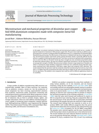
  • 8. J. Butt et al. / Journal of Materials Processing Technology 238 (2016) 96–107 103 0 1 2 3 4 5 6 7 8 9 10 0 5 10 15 20 Force(kN) Displacement (mm) Composite Aluminium 1050 Copper Fig. 14. Comparative Tensile Test. 3.4. Results from dog-bone tensile test This test was important to demonstrate the effectiveness of the process. In the lap test, only 12.5 mm of the foil was joined to another foil. In the peel test, although 150 mm length was joined, there were still only two foils involved. Those tests gave an indi- cation of the bond integrity and strength but to gain a better understanding, a multi-layer structure is needed. In a multi-layer structure, brazing is on both sides of the foil and it will truly test the integrity of the bond between the layers when subjected to ten- sile loading. Fig. 13 shows the fracture modes of the specimens. As expected, both aluminium and copper showed considerable neck- ing but the composite specimen did not show such characteristics. A composite of two materials is expected to have properties that either lie somewhere between the two or is completely different from the two materials from which it was made. Fig. 14 shows the curves for the three tested specimens. Both copper and aluminium, being ductile materials show a curve with well-defined elastic and plastic regions whereas it is not the case with the composite spec- imen. It showed an elastic region but the plastic region is much shorter as compared to the other two curves on the graph. It is important to note that the maximum force value for the solid 1050 aluminium specimen is 4.484 kN whereas the composite specimen showed a maximum force value of 4.98 kN, making it 11% stronger in comparison. It also has a higher modulus of elasticity (75 GPa) as compared to 1050 aluminium (70 GPa). This test demonstrates that the process is capable of producing a composite specimen that is stronger than the weaker of the two metals from which it was pro- duced. The reason for the high strength of the specimen is rather fundamental. The yield strengths of the three materials i.e., cop- per (140 MPa), aluminium (75 MPa) and brazing paste (45 MPa) tend to add up theoretically. They are adding up because the paste is making an intermetallic bond with the metal foil surface. The foils were stacked in the order that there was ‘aluminium-paste- copper-paste-aluminium’ and so on. Therefore, the bond between the paste and relative foil that it was bonded to, kept on adding the yield strengths. In theory, the strength keeps on increasing with the increase in the number of layers. Experiments do not always agree with theory but an increase in strength to a certain extent can be observed from Fig. 14. Furthermore, the layer of pate is also responsible for stopping the atoms of the metal from slipping upon application of stress and thus prohibiting any dislocations. This is the reason for the high strength but small plastic range of the composite specimen. The curves in Fig. 14 are the result of comparing pure copper, aluminium and composite (made by CMFM) specimens. This shows that CMFM is capable of producing a composite with good mechani- 0 1 2 3 4 5 6 7 8 9 0 5 10 15 20 Force(kN) Displacement (mm) Composite Aluminium 1050 Copper Fig. 15. Un-bonded versus bonded tensile test. cal properties but it is hard to access as to how good these properties really are. It can be seen that the composite is better than alu- minium but is nowhere close to the load values of copper. There is a way to analyse the expected curve for the composite specimen by making use of the rule of mixtures. It can predict the different properties of the composite but in this case, the focus is on the elastic modulus. Therefore, two dog bone specimens of aluminium and copper (Al = 1.4 mm and Cu = 1.3 mm, total thickness = 2.7 mm; same as the composite specimen) were fixed in grippers without any bonding and the resulting curve was compared to that of the composite. As expected, aluminium fractured before copper and gave a dip in the curve which was then taken over by copper and it went all the way until copper was fractured as well. The compari- son, as shown in Fig. 15, is very interesting and shows the extent to which the composite has matched with the un-bonded bi-material (Al/Cu) specimen. It shows a similar picture that was observed in Fig. 14 in that the composite fractures at a higher load value and possess a higher modulus of elasticity compared to aluminium (the weaker of the two base metals). A simple average of the elastic moduli for the two parent metals will show that the value for the composite (75 GPa) is a very good result that clearly demonstrate the capability of CMFM. Copper and 1050 aluminium, being ductile material show inclu- sions that act as tiny stress concentrations as shown in Fig. 16. They tend to follow two paths; either fracture or separate from the matrix. This leads to the growing of the voids that causes failure of the material. The composite specimens (Fig. 17a) show the layer of paste sandwiched between copper and aluminium. The layer of paste has cracks and holes as were seen in the SEM analysis of the peel spec- imens. However, the result is a specimen that is 11% stronger than aluminium but weaker than copper. Fig. 17b and c shows the SEM analysis of the two metal foils covered with paste and showing some inclusions at the fractured region. 4. Interfacial bonding A number of parts including single lap joints, peel specimens and tensile specimens have been produced using the principles of CMFM. All of them have been made by joining metal foils with the help of brazing paste and heating plates. It is important to under- stand the effect of brazing on the foils. Brazing is a process that has been around for decades and is widely used in industries for joining similar as well as dissimilar metals but its application for a process that is additive in nature is a new prospect. CMFM com- bines the flexibility and efficiency of the brazing process with the cutting and stacking of metal foils. Swift and Booker (2013, p. 330)
  • 9. 104 J. Butt et al. / Journal of Materials Processing Technology 238 (2016) 96–107 Fig. 16. SEM analysis of metals: (a) Copper; (b) 1050 Aluminium. Fig. 17. SEM analysis: (a) Composite specimen; (b) Copper layer; (c) Aluminium layer. put brazing in the category of economic and high quality metal joining methods. It provides good quality bonding with low dis- tortion, good surface finish, stress free bond surface but the time and temperature of the heat applied during the process needs to be controlled. Various types of materials have different properties and aluminium is one of the toughest metals to work with as it is not popular for its bonding capabilities due to the presence of an oxide layer. Therefore, it is essential to analyse the interfacial behaviour of the joint produced during the brazing process. In our previous work (Butt et al., 2015c), we analysed the effect of temperature during the production of Al/Cu single lap joint and showed that it did not affect the mechanical characteristics of the joint produced by the CMFM process. A single lap joint was easily made in 5 s as the joining area was very small (25 mm by 12.5 mm), with one of the plates set at 470 ◦C. It was also pointed out that the bond integrity is a function of the processing time and build requirements. The same heating time cannot be used for all materials and joint configurations as the paste requires an appropriate amount of time to penetrate the oxide layer
  • 10. J. Butt et al. / Journal of Materials Processing Technology 238 (2016) 96–107 105 Fig. 18. Mesh of Al/Cu T-peel joint. of aluminium. It must be noted that the interfacial bonding of dis- similar materials is a much more complex phenomenon compared to similar materials. In this particular case, three different materials are being bonded to each other namely aluminium, brazing paste and copper. The composite is made with alternate layers of the two base metals so the configuration is copper-paste-aluminium-paste- copper and so on. The three materials have their own unique set of properties that directly influence the formation of the bond made by the paste. In addition to the processing time and the type of part being built, properties of the materials being joined also play a significant role. A comparison has been shown in Section 3.1.1 between the shear strength of the bond made by the same paste when joining similar and dissimilar metals. It gives a very clear picture with the similar metal (Aluminium 1050) having a shear strength of 52 MPa whereas the dissimilar metals (Aluminium 1050 and copper) have a value of just 17.432 MPa. There is, however, a need to analyse this effect much further using more sophisticated and advanced methodologies at microscopic level to understand the interfacial bonding and factors to enhance its effectiveness to obtain better results. Murakami et al. (2003) and Xu et al. (2015) also emphasised on the use of short brazing cycle with fast heat-up and a very short holding time at maximum temperature to ensure the formation of strong bond. Therefore, a 3D model has been prepared in ANSYS and transient thermal analysis has been carried out to show the time needed to produce a T-peel joint using CMFM (Fig. 18). The simulation works as an aid to ensure that the foils and the paste will actually be at a particular temperature value and that the time would be enough to create an intermetallic bond. This analysis can aid in the production of various products in the future without any guess work regarding the time taken to join the metal foils irrespective of the number and joining area of the foils. The heating plates can be operated simultaneously as well as separately and depending on the thickness of the part being pro- duced, one or both plates could be turned on. In the case of a T-peel joint, only one plate has been turned on and set at a temperature of 470 ◦C as only two 0.1 mm foils are being joined together. The temperature distribution on the heated plates has been shown in Fig. 19 with the maximum value at 470 ◦C and a lowest value of 134 ◦C. The maximum temperature is at the bottom plate which has been set up at 470 ◦C and the lowest temperature is at the top plate. The joint itself is at 470 ◦C as shown in Fig. 20. The joining area is 150 mm by 25 mm and based on the good practice of keeping the Fig. 19. Temperature distribution of the plates. Fig. 20. Temperature distribution Al/Cu T-peel joint. brazing cycle short, it was observed that 10 s at the maximum tem- perature value can easily bond the required area. The temperature distribution obtained from the simulation can be used in the static structural analysis to analyse thermal stress and strain as a result of the heat applied during the brazing process. 5. Potential of application Parts produced by additive manufacturing are often criticized for not being strong enough for real world applications but the experiments of parts produced by CMFM show that it is not entirely true. The ability of CMFM to produce strong and high quality com- posites with the same ease as single material parts without the use of any additional equipment, makes it very economical. Produc- tion of composites is not easy and requires the use of expensive methods and machinery but CMFM can produce composites in the same way as single material parts without the use of any additional equipment. Due to cost and material restrictions, composites are gaining wide interest and a technology capable of producing them at a cheaper cost would certainly be a step forward in the right direction. Foils of varying thickness can be joined using this process
  • 11. 106 J. Butt et al. / Journal of Materials Processing Technology 238 (2016) 96–107 Fig. 21. Composite spanner produced by CMFM. which poses problems for some other methods making use of metal sheets. The work done by Prechtl et al. (2005) showed that when foils of less than 0.5 mm thickness are used, the products experience high staircase effect. It is not the case with CMFM which shows its effectiveness in producing a variety of composite materials. CMFM is capable of producing parts with complex geometries having good mechanical properties. Fig. 21 shows an open-ended spanner (pro- duced by CMFM) being compared to a spanner generally used in mechanical workshops. CMFM has the huge commercial implications it has reduced the limitations related to the production of composites. It has the abil- ity to use different metals provided the appropriate brazing paste is available, can work with varying thickness of foils that save money as foils are much cheaper than powder metals (in case of DMLS), and does not require post processing. The process can have vast appli- cations (metal products and composites) ranging from common mechanical parts to large scale industrial manufacturing. 6. Conclusions The potential of CMFM and its impact due to its simplicity as well as ease of operation has been shown in this research work. A 3D transien thermal analysis has been presented that can be used to produce parts in the future with this process and give more insight into the design parameters. The experimentation results clearly validate the effectiveness of the process. Lap-shear tests showed that the weaker parent material (1050 aluminium) fractured and not the bond between the foils. Foils of varying thick- nesses were tested to analyse the flexibility of the process. The joint tensile strength and bond shear strength were calculated by using thicker plates to fracture the interface and observe cohesion failure. The peel test showed similar results and microstructural analysis revealed a good proportion of bonded area. However, there were still some no-bonded areas that resulted in the formation of teeth like ends but the peel strength of the specimens did not vary much (minimum being 20.2 MPa and maximum 22.6 MPa). The comparative tensile dog-bone test showed that the composite specimen (produced by CMFM) was 11% stronger than the weaker parent metal (1050 aluminium) and had a higher modulus of elas- ticity (75 GPa). Microstructural analysis of the fractured surface showed a high proportion of bonded area with the presence of a few cracks and voids as were observed for the peel specimens. The final composite is stronger than 1050 aluminium and lighter than pure copper − these characteristics can be used for a number of applications including aircrafts, automobiles, construction, tooling etc. Funding statement This research received no specific grant from any funding agency in the public, commercial, or not-for-profit sectors. Acknowledgement The authors would like to thank Anglia Ruskin University for providing the equipment and testing facilities to carry out the research. References BS EN 1465: 2009. Adhesives—determination of tensile lap-shear strength of bonded assemblies. BS EN ISO 10365:1995. Adhesives—designation of main failure patterns. BS EN ISO 11339:2010, Adhesives—T-peel test for flexible-to-flexible bonded assemblies. BS EN ISO 6892-1:2009, Metallic materials—tensile testing, Part 1: method of test at ambient temperature. Balasubramanian, M., 2016. Characterization of diffusion-bonded titanium alloy and 304 stainless steel with Ag as an interlayer. Int. J. Adv. Manuf. Technol. 82 (1–4), 153–162. Baldan, A., 2012. Adhesion phenomena in bonded joints. Int. J. Adhes. Adhes. 38, 95–116. Butt, J., Mebrahtu, H., Shirvani, H., 2014. A novel rapid prototyping process for the production of metal parts. In: Proceedings of the Second International Conference on Advances in Civil, Structural and Mechanical Engineering-CSM, Birmingham, United Kingdom, pp. 26–29, http://dx.doi.org/10.15224/978-1- 63248-054-5-45. Butt, J., Mebrahtu, H., Shirvani, H., 2015a. Peel and tensile test investigation of aluminium 1050 foil parts made with a new additive manufacturing process. Int. J. Rapid Manuf. 5 (1), 95–115. Butt, J., Mebrahtu, H., Shirvani, H., 2016. Rapid prototyping by heat diffusion of metal foil and related mechanical testing. Int. J. Adv. Manuf. Technol. 2015, 1–10, http://dx.doi.org/10.1007/s00170-015-7882-8. Butt, J., Mebrahtu, H., Shirvani, H., 2015c. Thermo-mechanical analysis of dissimilar al/cu foil single lap joints made by composite metal foil manufacturing. World Acad. Sci. Eng. Technol. Int. J. Mech. Aerospa. Ind. Mech. Manuf. Eng. 10 (November (1)), 41–46. Butt, J., Mebrahtu, H., Shirvani, H., 2016. Strength analysis of aluminium foil parts made by composite metal foil manufacturing. Progress Addit. Manuf. 1 (1), 93–103, http://dx.doi.org/10.1007/s40964-016-0008-5. Da Silva, L.F.M., et al., 2009. Effect of material, geometry, surface treatment and environment on the shear strength of single lap joints. Int. J. Adhes. Adhes. 29 (6), 621–632. Ebnesajjad, S., Landrock, A.H., 2014. Adhesives Technology Handbook. William Andrew. Gaard, A., Krakhmalev, P., Bergstrom, J., 2006. Microstructural characterization and wear behaviour of (Fe,Ni)?TiC MMC prepared by DMLS. J. Alloys Compd. 421 (1–2), 166–171. Groover, M.P., 2007. Fundamentals of Modern Manufacturing: Materials Processes, and Systems. John Wiley & Sons. Gu, D., Shen, Y., 2006. WCCo particulate reinforcing Cu matrix composites produced by direct laser sintering. Mater. Lett. 60 (29–30), 3664–3668. He, P., Liu, D., 2006. Mechanism of forming interfacial intermetallic compounds at interface for solid state diffusion bonding of dissimilar materials. Mater. Sci. Eng. A 437 (2), 430–435. Kazakov, N.F. (Ed.), 2013. Elsevier. Kong, C.Y., Soar, R.C., 2005. Fabrication of metal–matrix composites and adaptive composites using ultrasonic consolidation process. Mater. Sci. Eng. A 412 (1–2), 12–18. Kong, C.Y., Soar, R.C., Dickens, P.M., 2004. Optimal process parameters for ultrasonic consolidation of 3003 aluminium. J. Mater. Process. Technol. 146 (2), 181–187. Laoui, T., Froyen, L., Kruth, J.P., 2000. Effect of mechanical alloying on selective laser sintering of WC–9CO powder. Powder Metall. 42 (3), 203–205. Li, Y., Liu, P., Wang, J., Ma, H., 2007. XRD and SEM analysis near the diffusion bonding interface of Mg/Al dissimilar materials. Vacuum 82 (1), 15–19. Liu, B., Bai, P.K., Cheng, J., 2008. Microstructure evolution of Mo-based composites during selective laser sintering and thermal processing. J. Comput. Theor. Nanosci. 5 (8), 1565–1569. Murakami, T., Nakata, K., Tong, H., Ushio, M., 2003. Dissimilar metal joining of aluminum to steel by MIG arc brazing using flux cored wire. ISIJ Int. 43 (10), 1596–1602. Nicholas, M.G., Joining processes: introduction to brazing and diffusion bonding’, 1998.
  • 12. J. Butt et al. / Journal of Materials Processing Technology 238 (2016) 96–107 107 Prechtl, M., Pursche, L., Otto, A., 2004. System technology and data preparation for automated laser assisted stacking of metal foil. In: Proc. of the 4th International Conference on Laser Assisted Net Shape Engineering – LANE, Germany, pp. 601–610. Prechtl, M., Otto, A., Geiger, M., 2005. Rapid tooling by laminated object manufacturing of metal foil. Trans. Tech. 6–8, 302–312. Rambo, C.R., Travitzky, N., Zimmermann, K., Greil, P., 2005. Synthesis of TiC/Ti?Cu composites by pressureless reactive infiltration of TiCu alloy into carbon preforms fabricated by 3D-printing. Mater. Lett. 59, 1028–1031. Sekuli´c, D.P., 2013. Advances in Brazing: Science, Technology and Applications. Elsevier. Simchi, A., Pohl, H., 2004. Direct laser sintering of iron–graphite powder mixture. Mater. Sci. Eng. A 383 (2), 191–200. Slocombe, A., Li, L., 2001. Selective laser sintering of TiC—Al2O3 composite with self propagating high-temperature synthesis. J. Mater. Process. Technol. 118, 173–178. Swift, K.G., Booker, J.D., 2013. Manufacturing Process Selection Handbook. Butterworth-Heinemann. Xiong, Y., Smugeresky, J.E., Ajdelsztajn, L., Schoenung, J.M., 2008. Fabrication of wc-co cermets by laser engineered net shaping. Mater. Sci. Eng. A 493 (1–2), 261–266. Xu, H.B., Sun, H.B., Yang, H., Chi, L.X., Chen, J., 2015. Microstructure and properties of joint for stirring brazing of dissimilar Al/Mg alloy during heating processes. Rare Met. 34 (4), 245–250. Zhan, Y., Han, J., Zhang, X., He, X., Li, Z., Du, S., 2001. Rapid prototyping and combustion synthesis of TiC/Ni functionally gradient materials. Mater. Sci. Eng. A 299, 218–224.