SlideShare ist ein Scribd-Unternehmen logo
1 von 4
Downloaden Sie, um offline zu lesen
IOSR Journal of Electrical and Electronics Engineering (IOSR-JEEE)
e-ISSN: 2278-1676,p-ISSN: 2320-3331, Volume 12, Issue 1 Ver. IV (Jan. – Feb. 2017), PP 35-38
www.iosrjournals.org
DOI: 10.9790/1676-1201043538 www.iosrjournals.org 35 | Page
A high stable on-chip CMOS temperature sensor
Jinghong Miao1
, Jiaqi Li2
1
(School of graduate, Tianjin Polytechnic University, China)
2
(School of Electronic and Information Engineering, Tianjin Polytechnic University, China)
Abstract: A high stable CMOS temperature sensor is presented. A low-pass filter circuit is added in the output
of traditional CMOS temperature sensor to improve the stability of its output,. The supply power voltage of the
temperature sensor is 1.8V. The PSRR of the temperature sensor is -82dB in low frequency state. And the PSRR
is -45dB in worst case. The OP-AMP of sensor has 63º phase margin. The output mode is voltage, whose
linearity error is less than 0.2% and resolution ratio is more than 2.6mV/℃.
Keywords: CMOS, temperature sensor, high stable, high precision, cascode
I. Introduction
CMOS temperature sensor which is used in many kinds of control chips has so many advantages, such
as small volume, low cost and low-power dissipation1
. There are two kinds of CMOS temperature sensor
structures. One use the sub-threshold MOSFET to sense temperature and the other use parasitic bipolar
transistor to sense the temperature2
. The former structure is not stable and work well as the temperature sensor
of integrated chip. By comparison, the latter one is more stable and the reason is that all of the MOSFETs and
parasitic bipolar transistors are working in saturation region. The circuit structure view of the later mentioned
above is shown in fig. 1. The output mode is voltage and the working principle is as follows: Assuming that the
breadth length ratio of MOSFET that M1 and M2 are equal, which means the current I1 and I2 are also equal.
Meanwhile, the base-emitter voltage of Q1 (Vbe1) and Q2 (Vbe2) are constant. When the current I2 increases, the
positive electrode voltage (V+) of operational amplifier (OP-AMP) also increases. The consequence is that the
output of OP-AMP increases, and then the current I2 decreases. During the whole process, the negative electrode
voltage (V-) of OP-AMP remain unchanged. So the OP-AMP is working in negative feedback mode and the two
input voltage of OP-AMP are equal, which means V+ = V-. The relationship among Vbe1, Vbe2, I2 and R1 can be
work out, as shown in equation 1.
2121be beVRIV  (1)
So, I2 can be expressed, as shown in equation 2.
  11be2be2 - RVVI  (2)
I2 is a value which proportional to temperature, because Vbe1 and Vbe2 are almost proportional to
temperature and R1 is independent of temperature. M2 and M3 constitute a current mirror structure. Assuming
that the breadth length ratio of MOSFET that M1 and M2 is n and R2 is independent of temperature, the value of
IPTAT is n times of I2. So IPTAT is proportional to temperature. In fact, the temperature coefficient of R1 and R2
can cancel each other3
.
OPAMP
M3M2M1
R1
Q1 Q2
IPTAT
VDD
GND
I1 I2
R2
Fig.1 the basic circuit structure of CMOS temperature sensor
Recently, the accuracy of the CMOS temperature sensor structure mentioned above is about 0.1℃.
Moreover, CMOS temperature sensor has a high power supply rejection ratio about -60dB and its work
temperature range is usually between 0℃and 85℃. The power consumption is usually less than 1mW. But the
lack of this kind of structure is over-dependence manufacturing matching. In fact, it is very difficult to fabricate
two exactly same MOSFETs M1 and M2. If no matching, the performance of the circuit will decline and
something unexpected will happen4,5
.
A high stable on-chip CMOS temperature sensor
DOI: 10.9790/1676-1201043538 www.iosrjournals.org 36 | Page
II. New Structure of CMOS Temperature Sensor
A high stable on-chip CMOS temperature sensor is proposed to solve the problem mentioned above.
Fig. 2 shows the whole circuit diagram which include four parts that temperature sensor core circuit, operational
amplifier, bias circuit and start circuit.
Vcc
Gnd
P4
P5
N1
pnp1 pnp2
·
·
`
·
P1 P2
R2R1
R3
P18
R5
R6R7
R8
VTEMP
P3
P17
P16P15
N9
N4
N6
N5 N7
N8
N11 N12
N10
N2 N3
P6 P7 P8 P9 P10P11
P13 P14
P12
pnp3 pnp4
C1
temperature sensor
core circuit
start circuit bias circuit operational amplifier
V-
V+
Figure 2 the circuit of CMOS temperature sensor
The circuit structure of fig. 1 need satisfy four-terminal balance in the same time. That is V+ = V- and
I2 = I1. In theory, it is impossible. As shown in the fig. 2, a P-type MOSFET P1 provides current for two branch
and add R1 and R2 to make two branch current matching. Assuming that the current of P1 is IP1 and V+ = V-, the
voltage between the two poles of the R1 (UR1) and R2 (UR2) are equal. When the value of R1 and R2 are same, the
current of R1 (IR1) must be same as R2 (IR1). Under normal circumstances, the ratio of emitter junction area for
pnp4 and pnp3 is 8. So the current of R3 (IR3) can be expressed, as shown in equation 3.
3
be
3
4bepnp3bepnp
3
R
V
R
VV
IR



 (3)
Where Vbepnp3 and Vbepnp4 is the base-emitter voltage of pnp3 and pnp4 and ΔVbe is the difference value
of them. From the equation 2, IP1 and IP2 are proportional to temperature. When IP2 flows through R5, a voltage
(VTEMP) will be generated and it is proportional to temperature.
Folded cascade amplifier is used in the structure shown in fig. 2 and the amplifier has a larger output
impedance than diode amplifier. Due to the diode amplifier use common source as the output, the output
impedance is low and it is difficult to make phase compensation without Miller compensation. However, Miller
compensation must cause a problem that establish a way between input and output of the amplifier, which will
make the PSRR of circuit reduce. The folded cascade amplifier do not exist the problem which exist in diode
amplifier, so it is so easy to compensate the phase. Moreover, the folded cascade amplifier structure cannot
cause oscillation because of the large output impedance. The function of bias circuit is generating some bias
voltages for OP-AMP. As shown in the fig. 2, the gate voltage of P6 and P7 is very stable and the influence is
small by the power fluctuation. And the gate voltage will be mirrored three times in the same time to provide
bias voltage for OP-AMP. Unfortunately the bias circuit have two quiescent operating point but only one is
needed, so a start circuit is necessary. The function of start circuit is to ensure the bias circuit working nonzero
quiescent operating point. So far the inverter is usually used in the structure of start circuit, but the consumption
is large. To reduce the consumption, a kind of start circuit is proposed shown as the fig. 2. When the system is
powered on, P5 opens and then the bias circuit will start working. Meanwhile, P4 opens and the voltage of P5
will increase and this condition will continue until P5 shutdown. R7 is a big resistance whose function is to help
capacitor (N1) discharge. The start circuit end-of-job.
In the structure shown in fig. 2, two kinds of compensation is added. One is that a p-type MOSFET is
added between the output of folded cascade amplifier and VCC, which can increase the phase margin of the
amplifier without any other introducing interference. The other is that join the low pass filter at the output port,
which can improve the PSRR in the high frequency. In general, the CMOS temperature sensor put forward in
this paper is more stable than conventional CMOS temperature sensor.
III. Simulation Result
Four kinds of simulation has been done for the sensor including DC, AC, TRAN and STB. The
relationship between the output voltages of temperature sensor and temperature is shown in fig. 3. It is obvious
that the voltage is proportional to temperature highly. Fig. 4 is the slope of curve in figure 3 and it shows that
the value of slope is limit between 2.605mV/℃ and 2.595mV/℃. By calculation, the maximal error is 0.33℃ in
the whole temperature range.
A high stable on-chip CMOS temperature sensor
DOI: 10.9790/1676-1201043538 www.iosrjournals.org 37 | Page
Fig. 3 the relationship between the output voltages of temperature sensor and temperature
Fig. 4 slope of curve in Fig. 3
Fig. 5 is the transient simulation curve of the temperature sensor at 27℃. The figure shows that the
built-up time is around 150us and the curve without over swing and long delay. Fig. 6 is the PSRR simulation
curve of the temperature sensor. The value of PSRR is around -82dB in low frequency and -45dB@10kHz. To
make the performance more vivid, a sine wave whose frequency is 10 kHz and amplitude is 180mV is added to
the power supply and the simulation result is shown in fig. 7. The interference almost does not affect the output
voltage of the sensor. So it is very stable.
Fig. 5 the transient simulation curve of temperature sensor in 27℃
Fig. 6 the simulation result of PSRR of the temperature sensor
A high stable on-chip CMOS temperature sensor
DOI: 10.9790/1676-1201043538 www.iosrjournals.org 38 | Page
Fig. 7 the transient simulation curve with power interference
Figure 8 is the STB simulation curve of the sensor, in which the dotted line is the phase curve and the full line is
the gain curve. From the fig. 8, the phase margin can be work out and its value is around 63º. It means that the
sensor circuit is stable and no more built-up time.
Fig. 8 the STB simulation curve of the sensor
IV. Conclusion
A high stable on-chip CMOS temperature sensor structure is presented. The sensor should work at
1.8V power supply and the working temperature range is between -40℃ and 125℃. The error is within ±0.02.
The resolution of output voltage is 2.6mV/℃. The PSRR is -82dB@0Hz and -45dB@10kHz. The built-up time
of voltage is less than 150us. The phase margin is about 63º. All simulation result can reflect that the sensor
presented has a good working stable, which means it can be used many kinds of on-chip temperature
measurement system.
Acknowledgements
This research is funded by Tianjin Research Program of Application Foundation and Advanced Technology
(No. 15JCYBJC16300), and The Science and Technology Plans of Tianjin(16JCTPJC45500).
References
[1] Hany Fathalla Hassan Mokbel. Optimization of the Mechanical Design of the Dual Axis Inertially Stabilized Platform for the Line
of Sight Stabilization[D]. Changchun University of Science and Technology, 2013.
[2] Ali Sahafi,Jafar Sobhi,Ziaddin Daie Koozehkanani. Nano Watt CMOS temperature sensor[J]. Analog Integrated Circuits and Signal
Processing,2013 ,753:.
[3] Xiaokang Guan,Xin Wang,Albert Wang,Bin Zhao. A 3 V 110 μW 3.1 ppm/°C curvature-compensated CMOS bandgap reference[J].
Analog Integrated Circuits and Signal Processing, 2010, 622:.
[4] Liangbo Xie,Jiaxin Liu,Yao Wang,Yu Han,Guangjun Wen. A low power CMOS voltage reference generator with temperature and
process compensation[J]. Analog Integrated Circuits and Signal Processing, 2014, 811:.
[5] Christian Jésus B. Fayomi,Gilson I. Wirth,Hervé Facpong Achigui,Akira Matsuzawa. Sub 1 V CMOS bandgap reference design
techniques: a survey[J]. Analog Integrated Circuits and Signal Processing, 2010, 622:.

Weitere ähnliche Inhalte

Was ist angesagt?

Operational Sequence WTA.04
Operational Sequence WTA.04Operational Sequence WTA.04
Operational Sequence WTA.04Michael Glover
 
Instrumentation Lab. Experiment #3 Report: Operational Amplifiers
Instrumentation Lab. Experiment #3 Report: Operational AmplifiersInstrumentation Lab. Experiment #3 Report: Operational Amplifiers
Instrumentation Lab. Experiment #3 Report: Operational Amplifiersmohammad zeyad
 
Exp. no. 4 setb118 Analog electronics
Exp. no. 4  setb118  Analog electronicsExp. no. 4  setb118  Analog electronics
Exp. no. 4 setb118 Analog electronicsOmkar Rane
 
EE375 Electronics 1: lab 3
EE375   Electronics 1: lab 3EE375   Electronics 1: lab 3
EE375 Electronics 1: lab 3Loren Schwappach
 
Operational Amplifier Design
Operational Amplifier DesignOperational Amplifier Design
Operational Amplifier DesignBharat Biyani
 
Lecture 06 transistorremodel
Lecture 06 transistorremodelLecture 06 transistorremodel
Lecture 06 transistorremodelIsmael Cayo Apaza
 
EE201 -Chapter 4
EE201 -Chapter 4 EE201 -Chapter 4
EE201 -Chapter 4 ruhiyah
 
Tutorial simulations-elec 380
Tutorial simulations-elec 380Tutorial simulations-elec 380
Tutorial simulations-elec 380Moez Ansary
 
OPERATIONAL AMPLIFIERS
OPERATIONAL AMPLIFIERSOPERATIONAL AMPLIFIERS
OPERATIONAL AMPLIFIERSTamilarasan N
 
DIFFERENTIAL AMPLIFIER using MOSFET
DIFFERENTIAL AMPLIFIER using MOSFETDIFFERENTIAL AMPLIFIER using MOSFET
DIFFERENTIAL AMPLIFIER using MOSFETPraveen Kumar
 
Lecture Notes: EEEC6440315 Communication Systems - Analogue Modulation
Lecture Notes:  EEEC6440315 Communication Systems - Analogue ModulationLecture Notes:  EEEC6440315 Communication Systems - Analogue Modulation
Lecture Notes: EEEC6440315 Communication Systems - Analogue ModulationAIMST University
 
Design of two stage OPAMP
Design of two stage OPAMPDesign of two stage OPAMP
Design of two stage OPAMPVishal Pathak
 

Was ist angesagt? (20)

EEL782_Project
EEL782_ProjectEEL782_Project
EEL782_Project
 
Manual 2
Manual 2Manual 2
Manual 2
 
Operational Sequence WTA.04
Operational Sequence WTA.04Operational Sequence WTA.04
Operational Sequence WTA.04
 
Instrumentation Lab. Experiment #3 Report: Operational Amplifiers
Instrumentation Lab. Experiment #3 Report: Operational AmplifiersInstrumentation Lab. Experiment #3 Report: Operational Amplifiers
Instrumentation Lab. Experiment #3 Report: Operational Amplifiers
 
Exp. no. 4 setb118 Analog electronics
Exp. no. 4  setb118  Analog electronicsExp. no. 4  setb118  Analog electronics
Exp. no. 4 setb118 Analog electronics
 
Smith Chart Laboratory
Smith Chart LaboratorySmith Chart Laboratory
Smith Chart Laboratory
 
Amplifier report
Amplifier reportAmplifier report
Amplifier report
 
EE375 Electronics 1: lab 3
EE375   Electronics 1: lab 3EE375   Electronics 1: lab 3
EE375 Electronics 1: lab 3
 
Operational Amplifier Design
Operational Amplifier DesignOperational Amplifier Design
Operational Amplifier Design
 
Lecture 06 transistorremodel
Lecture 06 transistorremodelLecture 06 transistorremodel
Lecture 06 transistorremodel
 
multistage amplifier Abhishek meena
 multistage amplifier Abhishek meena multistage amplifier Abhishek meena
multistage amplifier Abhishek meena
 
Lab1
Lab1Lab1
Lab1
 
EE201 -Chapter 4
EE201 -Chapter 4 EE201 -Chapter 4
EE201 -Chapter 4
 
Tutorial simulations-elec 380
Tutorial simulations-elec 380Tutorial simulations-elec 380
Tutorial simulations-elec 380
 
FINALREPORTOPAMP.docx(1)
FINALREPORTOPAMP.docx(1)FINALREPORTOPAMP.docx(1)
FINALREPORTOPAMP.docx(1)
 
OPERATIONAL AMPLIFIERS
OPERATIONAL AMPLIFIERSOPERATIONAL AMPLIFIERS
OPERATIONAL AMPLIFIERS
 
DIFFERENTIAL AMPLIFIER using MOSFET
DIFFERENTIAL AMPLIFIER using MOSFETDIFFERENTIAL AMPLIFIER using MOSFET
DIFFERENTIAL AMPLIFIER using MOSFET
 
Folded cascode1
Folded cascode1Folded cascode1
Folded cascode1
 
Lecture Notes: EEEC6440315 Communication Systems - Analogue Modulation
Lecture Notes:  EEEC6440315 Communication Systems - Analogue ModulationLecture Notes:  EEEC6440315 Communication Systems - Analogue Modulation
Lecture Notes: EEEC6440315 Communication Systems - Analogue Modulation
 
Design of two stage OPAMP
Design of two stage OPAMPDesign of two stage OPAMP
Design of two stage OPAMP
 

Ähnlich wie A high stable on-chip CMOS temperature sensor

DESIGN OF A CMOS BANDGAP REFERENCE WITH LOWTEMPERATURE COEFFICIENT AND HIGH P...
DESIGN OF A CMOS BANDGAP REFERENCE WITH LOWTEMPERATURE COEFFICIENT AND HIGH P...DESIGN OF A CMOS BANDGAP REFERENCE WITH LOWTEMPERATURE COEFFICIENT AND HIGH P...
DESIGN OF A CMOS BANDGAP REFERENCE WITH LOWTEMPERATURE COEFFICIENT AND HIGH P...VLSICS Design
 
A novel voltage reference without the operational amplifier and resistors
A novel voltage reference without the operational amplifier and resistorsA novel voltage reference without the operational amplifier and resistors
A novel voltage reference without the operational amplifier and resistorsIJRES Journal
 
Automated Air Cooled Three Level Inverter system using Arduino
Automated Air Cooled Three Level Inverter system using ArduinoAutomated Air Cooled Three Level Inverter system using Arduino
Automated Air Cooled Three Level Inverter system using ArduinoIJEEE
 
Modified Bidirectional Converter with Current Fed Inverter
Modified Bidirectional Converter with Current Fed InverterModified Bidirectional Converter with Current Fed Inverter
Modified Bidirectional Converter with Current Fed InverterIJPEDS-IAES
 
Intro electronics laboratory
Intro electronics laboratoryIntro electronics laboratory
Intro electronics laboratoryThinh Pham Quoc
 
A novel high-precision curvature-compensated CMOS bandgap reference without u...
A novel high-precision curvature-compensated CMOS bandgap reference without u...A novel high-precision curvature-compensated CMOS bandgap reference without u...
A novel high-precision curvature-compensated CMOS bandgap reference without u...IJRES Journal
 
Research on High Frequency PI Section Control of Electrochemical DC Power Supply
Research on High Frequency PI Section Control of Electrochemical DC Power SupplyResearch on High Frequency PI Section Control of Electrochemical DC Power Supply
Research on High Frequency PI Section Control of Electrochemical DC Power Supplyiosrjce
 
High Performance Temperature Insensitive Current Mode Rectifier without Diode
High Performance Temperature Insensitive Current Mode Rectifier without DiodeHigh Performance Temperature Insensitive Current Mode Rectifier without Diode
High Performance Temperature Insensitive Current Mode Rectifier without DiodeIOSR Journals
 
Soft Switched Multi-Output Flyback Converter with Voltage Doubler
Soft Switched Multi-Output Flyback Converter with Voltage DoublerSoft Switched Multi-Output Flyback Converter with Voltage Doubler
Soft Switched Multi-Output Flyback Converter with Voltage DoublerIJPEDS-IAES
 
Analysis and Characterization of Different Comparator Topologies
Analysis and Characterization of Different Comparator TopologiesAnalysis and Characterization of Different Comparator Topologies
Analysis and Characterization of Different Comparator TopologiesAalay Kapadia
 
Electrical Discharge Machining Flyback Converter using UC3842 Current Mode PW...
Electrical Discharge Machining Flyback Converter using UC3842 Current Mode PW...Electrical Discharge Machining Flyback Converter using UC3842 Current Mode PW...
Electrical Discharge Machining Flyback Converter using UC3842 Current Mode PW...IJPEDS-IAES
 
Research Inventy : International Journal of Engineering and Science
Research Inventy : International Journal of Engineering and ScienceResearch Inventy : International Journal of Engineering and Science
Research Inventy : International Journal of Engineering and Scienceinventy
 
A Simplified Design and Modeling of Boost Converter for Photovoltaic Sytem
A Simplified Design and Modeling of Boost Converter for Photovoltaic Sytem A Simplified Design and Modeling of Boost Converter for Photovoltaic Sytem
A Simplified Design and Modeling of Boost Converter for Photovoltaic Sytem IJECEIAES
 
Multisim_simulation_project_3_^0_4[1]-2.pptx
Multisim_simulation_project_3_^0_4[1]-2.pptxMultisim_simulation_project_3_^0_4[1]-2.pptx
Multisim_simulation_project_3_^0_4[1]-2.pptxwencove9
 
Comparison of PI and PID Controlled Bidirectional DC-DC Converter Systems
Comparison of PI and PID Controlled Bidirectional DC-DC Converter SystemsComparison of PI and PID Controlled Bidirectional DC-DC Converter Systems
Comparison of PI and PID Controlled Bidirectional DC-DC Converter SystemsIJPEDS-IAES
 

Ähnlich wie A high stable on-chip CMOS temperature sensor (20)

DESIGN OF A CMOS BANDGAP REFERENCE WITH LOWTEMPERATURE COEFFICIENT AND HIGH P...
DESIGN OF A CMOS BANDGAP REFERENCE WITH LOWTEMPERATURE COEFFICIENT AND HIGH P...DESIGN OF A CMOS BANDGAP REFERENCE WITH LOWTEMPERATURE COEFFICIENT AND HIGH P...
DESIGN OF A CMOS BANDGAP REFERENCE WITH LOWTEMPERATURE COEFFICIENT AND HIGH P...
 
A novel voltage reference without the operational amplifier and resistors
A novel voltage reference without the operational amplifier and resistorsA novel voltage reference without the operational amplifier and resistors
A novel voltage reference without the operational amplifier and resistors
 
Automated Air Cooled Three Level Inverter system using Arduino
Automated Air Cooled Three Level Inverter system using ArduinoAutomated Air Cooled Three Level Inverter system using Arduino
Automated Air Cooled Three Level Inverter system using Arduino
 
Modified Bidirectional Converter with Current Fed Inverter
Modified Bidirectional Converter with Current Fed InverterModified Bidirectional Converter with Current Fed Inverter
Modified Bidirectional Converter with Current Fed Inverter
 
Intro electronics laboratory
Intro electronics laboratoryIntro electronics laboratory
Intro electronics laboratory
 
A novel high-precision curvature-compensated CMOS bandgap reference without u...
A novel high-precision curvature-compensated CMOS bandgap reference without u...A novel high-precision curvature-compensated CMOS bandgap reference without u...
A novel high-precision curvature-compensated CMOS bandgap reference without u...
 
N012628790
N012628790N012628790
N012628790
 
Research on High Frequency PI Section Control of Electrochemical DC Power Supply
Research on High Frequency PI Section Control of Electrochemical DC Power SupplyResearch on High Frequency PI Section Control of Electrochemical DC Power Supply
Research on High Frequency PI Section Control of Electrochemical DC Power Supply
 
N012628790
N012628790N012628790
N012628790
 
High Performance Temperature Insensitive Current Mode Rectifier without Diode
High Performance Temperature Insensitive Current Mode Rectifier without DiodeHigh Performance Temperature Insensitive Current Mode Rectifier without Diode
High Performance Temperature Insensitive Current Mode Rectifier without Diode
 
High Performance Temperature Insensitive Current Mode Rectifier without Diode
High Performance Temperature Insensitive Current Mode Rectifier without DiodeHigh Performance Temperature Insensitive Current Mode Rectifier without Diode
High Performance Temperature Insensitive Current Mode Rectifier without Diode
 
Soft Switched Multi-Output Flyback Converter with Voltage Doubler
Soft Switched Multi-Output Flyback Converter with Voltage DoublerSoft Switched Multi-Output Flyback Converter with Voltage Doubler
Soft Switched Multi-Output Flyback Converter with Voltage Doubler
 
Analysis and Characterization of Different Comparator Topologies
Analysis and Characterization of Different Comparator TopologiesAnalysis and Characterization of Different Comparator Topologies
Analysis and Characterization of Different Comparator Topologies
 
Electrical Discharge Machining Flyback Converter using UC3842 Current Mode PW...
Electrical Discharge Machining Flyback Converter using UC3842 Current Mode PW...Electrical Discharge Machining Flyback Converter using UC3842 Current Mode PW...
Electrical Discharge Machining Flyback Converter using UC3842 Current Mode PW...
 
Research Inventy : International Journal of Engineering and Science
Research Inventy : International Journal of Engineering and ScienceResearch Inventy : International Journal of Engineering and Science
Research Inventy : International Journal of Engineering and Science
 
A Simplified Design and Modeling of Boost Converter for Photovoltaic Sytem
A Simplified Design and Modeling of Boost Converter for Photovoltaic Sytem A Simplified Design and Modeling of Boost Converter for Photovoltaic Sytem
A Simplified Design and Modeling of Boost Converter for Photovoltaic Sytem
 
Multisim_simulation_project_3_^0_4[1]-2.pptx
Multisim_simulation_project_3_^0_4[1]-2.pptxMultisim_simulation_project_3_^0_4[1]-2.pptx
Multisim_simulation_project_3_^0_4[1]-2.pptx
 
Comparison of PI and PID Controlled Bidirectional DC-DC Converter Systems
Comparison of PI and PID Controlled Bidirectional DC-DC Converter SystemsComparison of PI and PID Controlled Bidirectional DC-DC Converter Systems
Comparison of PI and PID Controlled Bidirectional DC-DC Converter Systems
 
E1103043235
E1103043235E1103043235
E1103043235
 
IEEE 2004
IEEE 2004IEEE 2004
IEEE 2004
 

Mehr von IOSRJEEE

GM Distributed Generation Inverters in a Micro grid by Controlling Energy Man...
GM Distributed Generation Inverters in a Micro grid by Controlling Energy Man...GM Distributed Generation Inverters in a Micro grid by Controlling Energy Man...
GM Distributed Generation Inverters in a Micro grid by Controlling Energy Man...IOSRJEEE
 
Load Performances of a PIC Based Speed Governor for Micro Hydro Power Plant
Load Performances of a PIC Based Speed Governor for Micro Hydro Power PlantLoad Performances of a PIC Based Speed Governor for Micro Hydro Power Plant
Load Performances of a PIC Based Speed Governor for Micro Hydro Power PlantIOSRJEEE
 
A New Design in Parabolic Trough Using Heat Retention
A New Design in Parabolic Trough Using Heat RetentionA New Design in Parabolic Trough Using Heat Retention
A New Design in Parabolic Trough Using Heat RetentionIOSRJEEE
 
Investigation of Power Quality Indices in Jordanian Distribution Grid
Investigation of Power Quality Indices in Jordanian Distribution GridInvestigation of Power Quality Indices in Jordanian Distribution Grid
Investigation of Power Quality Indices in Jordanian Distribution GridIOSRJEEE
 
Improving Distribution System Performance in Deregulated Electricity Industry...
Improving Distribution System Performance in Deregulated Electricity Industry...Improving Distribution System Performance in Deregulated Electricity Industry...
Improving Distribution System Performance in Deregulated Electricity Industry...IOSRJEEE
 
High Efficiency Dc-Dc Converter for Renewable Energy Applications and High Vo...
High Efficiency Dc-Dc Converter for Renewable Energy Applications and High Vo...High Efficiency Dc-Dc Converter for Renewable Energy Applications and High Vo...
High Efficiency Dc-Dc Converter for Renewable Energy Applications and High Vo...IOSRJEEE
 
Performance Indicators For Grid-Connected PV Systems: A Case Study In Casabla...
Performance Indicators For Grid-Connected PV Systems: A Case Study In Casabla...Performance Indicators For Grid-Connected PV Systems: A Case Study In Casabla...
Performance Indicators For Grid-Connected PV Systems: A Case Study In Casabla...IOSRJEEE
 
A Review of Gas Sensors Based on Semiconducting Metal Oxide
A Review of Gas Sensors Based on Semiconducting Metal OxideA Review of Gas Sensors Based on Semiconducting Metal Oxide
A Review of Gas Sensors Based on Semiconducting Metal OxideIOSRJEEE
 
Stability Control System for a Two-Wheeler
Stability Control System for a Two-WheelerStability Control System for a Two-Wheeler
Stability Control System for a Two-WheelerIOSRJEEE
 
Voltage Sag and Swell Identification Using FFT Analysis and Mitigation with DVR
Voltage Sag and Swell Identification Using FFT Analysis and Mitigation with DVRVoltage Sag and Swell Identification Using FFT Analysis and Mitigation with DVR
Voltage Sag and Swell Identification Using FFT Analysis and Mitigation with DVRIOSRJEEE
 
Design of Intrusion Tolerance System based on Service Redundancy Level
Design of Intrusion Tolerance System based on Service Redundancy LevelDesign of Intrusion Tolerance System based on Service Redundancy Level
Design of Intrusion Tolerance System based on Service Redundancy LevelIOSRJEEE
 
Compensation of Harmonics of Fully Controlled Loads by Using SAHF
Compensation of Harmonics of Fully Controlled Loads by Using SAHFCompensation of Harmonics of Fully Controlled Loads by Using SAHF
Compensation of Harmonics of Fully Controlled Loads by Using SAHFIOSRJEEE
 
Design of Half Bridge LLC Resonant Converter for Low Voltage Dc Applications
Design of Half Bridge LLC Resonant Converter for Low Voltage Dc ApplicationsDesign of Half Bridge LLC Resonant Converter for Low Voltage Dc Applications
Design of Half Bridge LLC Resonant Converter for Low Voltage Dc ApplicationsIOSRJEEE
 
Design of the Pulse Oximetry Measurement Circuit and Its Sensing System Based...
Design of the Pulse Oximetry Measurement Circuit and Its Sensing System Based...Design of the Pulse Oximetry Measurement Circuit and Its Sensing System Based...
Design of the Pulse Oximetry Measurement Circuit and Its Sensing System Based...IOSRJEEE
 
Design of an Integrated Power Factor Converter with PI Controller for Low Pow...
Design of an Integrated Power Factor Converter with PI Controller for Low Pow...Design of an Integrated Power Factor Converter with PI Controller for Low Pow...
Design of an Integrated Power Factor Converter with PI Controller for Low Pow...IOSRJEEE
 
Magneto Optic Current Transformer Technology (MOCT)
Magneto Optic Current Transformer Technology (MOCT)Magneto Optic Current Transformer Technology (MOCT)
Magneto Optic Current Transformer Technology (MOCT)IOSRJEEE
 
On Essentiality of RoHS in EE R&D Ecosystem
On Essentiality of RoHS in EE R&D EcosystemOn Essentiality of RoHS in EE R&D Ecosystem
On Essentiality of RoHS in EE R&D EcosystemIOSRJEEE
 
Improvement of Load Power Factor by Using Capacitor
Improvement of Load Power Factor by Using CapacitorImprovement of Load Power Factor by Using Capacitor
Improvement of Load Power Factor by Using CapacitorIOSRJEEE
 
Modeling and Simulation of Three Phase Induction Machine Using Written Pole T...
Modeling and Simulation of Three Phase Induction Machine Using Written Pole T...Modeling and Simulation of Three Phase Induction Machine Using Written Pole T...
Modeling and Simulation of Three Phase Induction Machine Using Written Pole T...IOSRJEEE
 
Design of LED Driver Power Based on LNK417EG
Design of LED Driver Power Based on LNK417EGDesign of LED Driver Power Based on LNK417EG
Design of LED Driver Power Based on LNK417EGIOSRJEEE
 

Mehr von IOSRJEEE (20)

GM Distributed Generation Inverters in a Micro grid by Controlling Energy Man...
GM Distributed Generation Inverters in a Micro grid by Controlling Energy Man...GM Distributed Generation Inverters in a Micro grid by Controlling Energy Man...
GM Distributed Generation Inverters in a Micro grid by Controlling Energy Man...
 
Load Performances of a PIC Based Speed Governor for Micro Hydro Power Plant
Load Performances of a PIC Based Speed Governor for Micro Hydro Power PlantLoad Performances of a PIC Based Speed Governor for Micro Hydro Power Plant
Load Performances of a PIC Based Speed Governor for Micro Hydro Power Plant
 
A New Design in Parabolic Trough Using Heat Retention
A New Design in Parabolic Trough Using Heat RetentionA New Design in Parabolic Trough Using Heat Retention
A New Design in Parabolic Trough Using Heat Retention
 
Investigation of Power Quality Indices in Jordanian Distribution Grid
Investigation of Power Quality Indices in Jordanian Distribution GridInvestigation of Power Quality Indices in Jordanian Distribution Grid
Investigation of Power Quality Indices in Jordanian Distribution Grid
 
Improving Distribution System Performance in Deregulated Electricity Industry...
Improving Distribution System Performance in Deregulated Electricity Industry...Improving Distribution System Performance in Deregulated Electricity Industry...
Improving Distribution System Performance in Deregulated Electricity Industry...
 
High Efficiency Dc-Dc Converter for Renewable Energy Applications and High Vo...
High Efficiency Dc-Dc Converter for Renewable Energy Applications and High Vo...High Efficiency Dc-Dc Converter for Renewable Energy Applications and High Vo...
High Efficiency Dc-Dc Converter for Renewable Energy Applications and High Vo...
 
Performance Indicators For Grid-Connected PV Systems: A Case Study In Casabla...
Performance Indicators For Grid-Connected PV Systems: A Case Study In Casabla...Performance Indicators For Grid-Connected PV Systems: A Case Study In Casabla...
Performance Indicators For Grid-Connected PV Systems: A Case Study In Casabla...
 
A Review of Gas Sensors Based on Semiconducting Metal Oxide
A Review of Gas Sensors Based on Semiconducting Metal OxideA Review of Gas Sensors Based on Semiconducting Metal Oxide
A Review of Gas Sensors Based on Semiconducting Metal Oxide
 
Stability Control System for a Two-Wheeler
Stability Control System for a Two-WheelerStability Control System for a Two-Wheeler
Stability Control System for a Two-Wheeler
 
Voltage Sag and Swell Identification Using FFT Analysis and Mitigation with DVR
Voltage Sag and Swell Identification Using FFT Analysis and Mitigation with DVRVoltage Sag and Swell Identification Using FFT Analysis and Mitigation with DVR
Voltage Sag and Swell Identification Using FFT Analysis and Mitigation with DVR
 
Design of Intrusion Tolerance System based on Service Redundancy Level
Design of Intrusion Tolerance System based on Service Redundancy LevelDesign of Intrusion Tolerance System based on Service Redundancy Level
Design of Intrusion Tolerance System based on Service Redundancy Level
 
Compensation of Harmonics of Fully Controlled Loads by Using SAHF
Compensation of Harmonics of Fully Controlled Loads by Using SAHFCompensation of Harmonics of Fully Controlled Loads by Using SAHF
Compensation of Harmonics of Fully Controlled Loads by Using SAHF
 
Design of Half Bridge LLC Resonant Converter for Low Voltage Dc Applications
Design of Half Bridge LLC Resonant Converter for Low Voltage Dc ApplicationsDesign of Half Bridge LLC Resonant Converter for Low Voltage Dc Applications
Design of Half Bridge LLC Resonant Converter for Low Voltage Dc Applications
 
Design of the Pulse Oximetry Measurement Circuit and Its Sensing System Based...
Design of the Pulse Oximetry Measurement Circuit and Its Sensing System Based...Design of the Pulse Oximetry Measurement Circuit and Its Sensing System Based...
Design of the Pulse Oximetry Measurement Circuit and Its Sensing System Based...
 
Design of an Integrated Power Factor Converter with PI Controller for Low Pow...
Design of an Integrated Power Factor Converter with PI Controller for Low Pow...Design of an Integrated Power Factor Converter with PI Controller for Low Pow...
Design of an Integrated Power Factor Converter with PI Controller for Low Pow...
 
Magneto Optic Current Transformer Technology (MOCT)
Magneto Optic Current Transformer Technology (MOCT)Magneto Optic Current Transformer Technology (MOCT)
Magneto Optic Current Transformer Technology (MOCT)
 
On Essentiality of RoHS in EE R&D Ecosystem
On Essentiality of RoHS in EE R&D EcosystemOn Essentiality of RoHS in EE R&D Ecosystem
On Essentiality of RoHS in EE R&D Ecosystem
 
Improvement of Load Power Factor by Using Capacitor
Improvement of Load Power Factor by Using CapacitorImprovement of Load Power Factor by Using Capacitor
Improvement of Load Power Factor by Using Capacitor
 
Modeling and Simulation of Three Phase Induction Machine Using Written Pole T...
Modeling and Simulation of Three Phase Induction Machine Using Written Pole T...Modeling and Simulation of Three Phase Induction Machine Using Written Pole T...
Modeling and Simulation of Three Phase Induction Machine Using Written Pole T...
 
Design of LED Driver Power Based on LNK417EG
Design of LED Driver Power Based on LNK417EGDesign of LED Driver Power Based on LNK417EG
Design of LED Driver Power Based on LNK417EG
 

Kürzlich hochgeladen

The SRE Report 2024 - Great Findings for the teams
The SRE Report 2024 - Great Findings for the teamsThe SRE Report 2024 - Great Findings for the teams
The SRE Report 2024 - Great Findings for the teamsDILIPKUMARMONDAL6
 
THE SENDAI FRAMEWORK FOR DISASTER RISK REDUCTION
THE SENDAI FRAMEWORK FOR DISASTER RISK REDUCTIONTHE SENDAI FRAMEWORK FOR DISASTER RISK REDUCTION
THE SENDAI FRAMEWORK FOR DISASTER RISK REDUCTIONjhunlian
 
Arduino_CSE ece ppt for working and principal of arduino.ppt
Arduino_CSE ece ppt for working and principal of arduino.pptArduino_CSE ece ppt for working and principal of arduino.ppt
Arduino_CSE ece ppt for working and principal of arduino.pptSAURABHKUMAR892774
 
Energy Awareness training ppt for manufacturing process.pptx
Energy Awareness training ppt for manufacturing process.pptxEnergy Awareness training ppt for manufacturing process.pptx
Energy Awareness training ppt for manufacturing process.pptxsiddharthjain2303
 
Main Memory Management in Operating System
Main Memory Management in Operating SystemMain Memory Management in Operating System
Main Memory Management in Operating SystemRashmi Bhat
 
Internet of things -Arshdeep Bahga .pptx
Internet of things -Arshdeep Bahga .pptxInternet of things -Arshdeep Bahga .pptx
Internet of things -Arshdeep Bahga .pptxVelmuruganTECE
 
Introduction to Machine Learning Unit-3 for II MECH
Introduction to Machine Learning Unit-3 for II MECHIntroduction to Machine Learning Unit-3 for II MECH
Introduction to Machine Learning Unit-3 for II MECHC Sai Kiran
 
National Level Hackathon Participation Certificate.pdf
National Level Hackathon Participation Certificate.pdfNational Level Hackathon Participation Certificate.pdf
National Level Hackathon Participation Certificate.pdfRajuKanojiya4
 
Research Methodology for Engineering pdf
Research Methodology for Engineering pdfResearch Methodology for Engineering pdf
Research Methodology for Engineering pdfCaalaaAbdulkerim
 
UNIT III ANALOG ELECTRONICS (BASIC ELECTRONICS)
UNIT III ANALOG ELECTRONICS (BASIC ELECTRONICS)UNIT III ANALOG ELECTRONICS (BASIC ELECTRONICS)
UNIT III ANALOG ELECTRONICS (BASIC ELECTRONICS)Dr SOUNDIRARAJ N
 
Concrete Mix Design - IS 10262-2019 - .pptx
Concrete Mix Design - IS 10262-2019 - .pptxConcrete Mix Design - IS 10262-2019 - .pptx
Concrete Mix Design - IS 10262-2019 - .pptxKartikeyaDwivedi3
 
Correctly Loading Incremental Data at Scale
Correctly Loading Incremental Data at ScaleCorrectly Loading Incremental Data at Scale
Correctly Loading Incremental Data at ScaleAlluxio, Inc.
 
NO1 Certified Black Magic Specialist Expert Amil baba in Uae Dubai Abu Dhabi ...
NO1 Certified Black Magic Specialist Expert Amil baba in Uae Dubai Abu Dhabi ...NO1 Certified Black Magic Specialist Expert Amil baba in Uae Dubai Abu Dhabi ...
NO1 Certified Black Magic Specialist Expert Amil baba in Uae Dubai Abu Dhabi ...Amil Baba Dawood bangali
 
Indian Dairy Industry Present Status and.ppt
Indian Dairy Industry Present Status and.pptIndian Dairy Industry Present Status and.ppt
Indian Dairy Industry Present Status and.pptMadan Karki
 
Vishratwadi & Ghorpadi Bridge Tender documents
Vishratwadi & Ghorpadi Bridge Tender documentsVishratwadi & Ghorpadi Bridge Tender documents
Vishratwadi & Ghorpadi Bridge Tender documentsSachinPawar510423
 
Virtual memory management in Operating System
Virtual memory management in Operating SystemVirtual memory management in Operating System
Virtual memory management in Operating SystemRashmi Bhat
 
Software and Systems Engineering Standards: Verification and Validation of Sy...
Software and Systems Engineering Standards: Verification and Validation of Sy...Software and Systems Engineering Standards: Verification and Validation of Sy...
Software and Systems Engineering Standards: Verification and Validation of Sy...VICTOR MAESTRE RAMIREZ
 
welding defects observed during the welding
welding defects observed during the weldingwelding defects observed during the welding
welding defects observed during the weldingMuhammadUzairLiaqat
 

Kürzlich hochgeladen (20)

The SRE Report 2024 - Great Findings for the teams
The SRE Report 2024 - Great Findings for the teamsThe SRE Report 2024 - Great Findings for the teams
The SRE Report 2024 - Great Findings for the teams
 
THE SENDAI FRAMEWORK FOR DISASTER RISK REDUCTION
THE SENDAI FRAMEWORK FOR DISASTER RISK REDUCTIONTHE SENDAI FRAMEWORK FOR DISASTER RISK REDUCTION
THE SENDAI FRAMEWORK FOR DISASTER RISK REDUCTION
 
Arduino_CSE ece ppt for working and principal of arduino.ppt
Arduino_CSE ece ppt for working and principal of arduino.pptArduino_CSE ece ppt for working and principal of arduino.ppt
Arduino_CSE ece ppt for working and principal of arduino.ppt
 
Design and analysis of solar grass cutter.pdf
Design and analysis of solar grass cutter.pdfDesign and analysis of solar grass cutter.pdf
Design and analysis of solar grass cutter.pdf
 
Energy Awareness training ppt for manufacturing process.pptx
Energy Awareness training ppt for manufacturing process.pptxEnergy Awareness training ppt for manufacturing process.pptx
Energy Awareness training ppt for manufacturing process.pptx
 
Main Memory Management in Operating System
Main Memory Management in Operating SystemMain Memory Management in Operating System
Main Memory Management in Operating System
 
Internet of things -Arshdeep Bahga .pptx
Internet of things -Arshdeep Bahga .pptxInternet of things -Arshdeep Bahga .pptx
Internet of things -Arshdeep Bahga .pptx
 
Introduction to Machine Learning Unit-3 for II MECH
Introduction to Machine Learning Unit-3 for II MECHIntroduction to Machine Learning Unit-3 for II MECH
Introduction to Machine Learning Unit-3 for II MECH
 
National Level Hackathon Participation Certificate.pdf
National Level Hackathon Participation Certificate.pdfNational Level Hackathon Participation Certificate.pdf
National Level Hackathon Participation Certificate.pdf
 
POWER SYSTEMS-1 Complete notes examples
POWER SYSTEMS-1 Complete notes  examplesPOWER SYSTEMS-1 Complete notes  examples
POWER SYSTEMS-1 Complete notes examples
 
Research Methodology for Engineering pdf
Research Methodology for Engineering pdfResearch Methodology for Engineering pdf
Research Methodology for Engineering pdf
 
UNIT III ANALOG ELECTRONICS (BASIC ELECTRONICS)
UNIT III ANALOG ELECTRONICS (BASIC ELECTRONICS)UNIT III ANALOG ELECTRONICS (BASIC ELECTRONICS)
UNIT III ANALOG ELECTRONICS (BASIC ELECTRONICS)
 
Concrete Mix Design - IS 10262-2019 - .pptx
Concrete Mix Design - IS 10262-2019 - .pptxConcrete Mix Design - IS 10262-2019 - .pptx
Concrete Mix Design - IS 10262-2019 - .pptx
 
Correctly Loading Incremental Data at Scale
Correctly Loading Incremental Data at ScaleCorrectly Loading Incremental Data at Scale
Correctly Loading Incremental Data at Scale
 
NO1 Certified Black Magic Specialist Expert Amil baba in Uae Dubai Abu Dhabi ...
NO1 Certified Black Magic Specialist Expert Amil baba in Uae Dubai Abu Dhabi ...NO1 Certified Black Magic Specialist Expert Amil baba in Uae Dubai Abu Dhabi ...
NO1 Certified Black Magic Specialist Expert Amil baba in Uae Dubai Abu Dhabi ...
 
Indian Dairy Industry Present Status and.ppt
Indian Dairy Industry Present Status and.pptIndian Dairy Industry Present Status and.ppt
Indian Dairy Industry Present Status and.ppt
 
Vishratwadi & Ghorpadi Bridge Tender documents
Vishratwadi & Ghorpadi Bridge Tender documentsVishratwadi & Ghorpadi Bridge Tender documents
Vishratwadi & Ghorpadi Bridge Tender documents
 
Virtual memory management in Operating System
Virtual memory management in Operating SystemVirtual memory management in Operating System
Virtual memory management in Operating System
 
Software and Systems Engineering Standards: Verification and Validation of Sy...
Software and Systems Engineering Standards: Verification and Validation of Sy...Software and Systems Engineering Standards: Verification and Validation of Sy...
Software and Systems Engineering Standards: Verification and Validation of Sy...
 
welding defects observed during the welding
welding defects observed during the weldingwelding defects observed during the welding
welding defects observed during the welding
 

A high stable on-chip CMOS temperature sensor

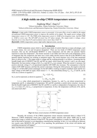
  • 1. IOSR Journal of Electrical and Electronics Engineering (IOSR-JEEE) e-ISSN: 2278-1676,p-ISSN: 2320-3331, Volume 12, Issue 1 Ver. IV (Jan. – Feb. 2017), PP 35-38 www.iosrjournals.org DOI: 10.9790/1676-1201043538 www.iosrjournals.org 35 | Page A high stable on-chip CMOS temperature sensor Jinghong Miao1 , Jiaqi Li2 1 (School of graduate, Tianjin Polytechnic University, China) 2 (School of Electronic and Information Engineering, Tianjin Polytechnic University, China) Abstract: A high stable CMOS temperature sensor is presented. A low-pass filter circuit is added in the output of traditional CMOS temperature sensor to improve the stability of its output,. The supply power voltage of the temperature sensor is 1.8V. The PSRR of the temperature sensor is -82dB in low frequency state. And the PSRR is -45dB in worst case. The OP-AMP of sensor has 63º phase margin. The output mode is voltage, whose linearity error is less than 0.2% and resolution ratio is more than 2.6mV/℃. Keywords: CMOS, temperature sensor, high stable, high precision, cascode I. Introduction CMOS temperature sensor which is used in many kinds of control chips has so many advantages, such as small volume, low cost and low-power dissipation1 . There are two kinds of CMOS temperature sensor structures. One use the sub-threshold MOSFET to sense temperature and the other use parasitic bipolar transistor to sense the temperature2 . The former structure is not stable and work well as the temperature sensor of integrated chip. By comparison, the latter one is more stable and the reason is that all of the MOSFETs and parasitic bipolar transistors are working in saturation region. The circuit structure view of the later mentioned above is shown in fig. 1. The output mode is voltage and the working principle is as follows: Assuming that the breadth length ratio of MOSFET that M1 and M2 are equal, which means the current I1 and I2 are also equal. Meanwhile, the base-emitter voltage of Q1 (Vbe1) and Q2 (Vbe2) are constant. When the current I2 increases, the positive electrode voltage (V+) of operational amplifier (OP-AMP) also increases. The consequence is that the output of OP-AMP increases, and then the current I2 decreases. During the whole process, the negative electrode voltage (V-) of OP-AMP remain unchanged. So the OP-AMP is working in negative feedback mode and the two input voltage of OP-AMP are equal, which means V+ = V-. The relationship among Vbe1, Vbe2, I2 and R1 can be work out, as shown in equation 1. 2121be beVRIV  (1) So, I2 can be expressed, as shown in equation 2.   11be2be2 - RVVI  (2) I2 is a value which proportional to temperature, because Vbe1 and Vbe2 are almost proportional to temperature and R1 is independent of temperature. M2 and M3 constitute a current mirror structure. Assuming that the breadth length ratio of MOSFET that M1 and M2 is n and R2 is independent of temperature, the value of IPTAT is n times of I2. So IPTAT is proportional to temperature. In fact, the temperature coefficient of R1 and R2 can cancel each other3 . OPAMP M3M2M1 R1 Q1 Q2 IPTAT VDD GND I1 I2 R2 Fig.1 the basic circuit structure of CMOS temperature sensor Recently, the accuracy of the CMOS temperature sensor structure mentioned above is about 0.1℃. Moreover, CMOS temperature sensor has a high power supply rejection ratio about -60dB and its work temperature range is usually between 0℃and 85℃. The power consumption is usually less than 1mW. But the lack of this kind of structure is over-dependence manufacturing matching. In fact, it is very difficult to fabricate two exactly same MOSFETs M1 and M2. If no matching, the performance of the circuit will decline and something unexpected will happen4,5 .
  • 2. A high stable on-chip CMOS temperature sensor DOI: 10.9790/1676-1201043538 www.iosrjournals.org 36 | Page II. New Structure of CMOS Temperature Sensor A high stable on-chip CMOS temperature sensor is proposed to solve the problem mentioned above. Fig. 2 shows the whole circuit diagram which include four parts that temperature sensor core circuit, operational amplifier, bias circuit and start circuit. Vcc Gnd P4 P5 N1 pnp1 pnp2 · · ` · P1 P2 R2R1 R3 P18 R5 R6R7 R8 VTEMP P3 P17 P16P15 N9 N4 N6 N5 N7 N8 N11 N12 N10 N2 N3 P6 P7 P8 P9 P10P11 P13 P14 P12 pnp3 pnp4 C1 temperature sensor core circuit start circuit bias circuit operational amplifier V- V+ Figure 2 the circuit of CMOS temperature sensor The circuit structure of fig. 1 need satisfy four-terminal balance in the same time. That is V+ = V- and I2 = I1. In theory, it is impossible. As shown in the fig. 2, a P-type MOSFET P1 provides current for two branch and add R1 and R2 to make two branch current matching. Assuming that the current of P1 is IP1 and V+ = V-, the voltage between the two poles of the R1 (UR1) and R2 (UR2) are equal. When the value of R1 and R2 are same, the current of R1 (IR1) must be same as R2 (IR1). Under normal circumstances, the ratio of emitter junction area for pnp4 and pnp3 is 8. So the current of R3 (IR3) can be expressed, as shown in equation 3. 3 be 3 4bepnp3bepnp 3 R V R VV IR     (3) Where Vbepnp3 and Vbepnp4 is the base-emitter voltage of pnp3 and pnp4 and ΔVbe is the difference value of them. From the equation 2, IP1 and IP2 are proportional to temperature. When IP2 flows through R5, a voltage (VTEMP) will be generated and it is proportional to temperature. Folded cascade amplifier is used in the structure shown in fig. 2 and the amplifier has a larger output impedance than diode amplifier. Due to the diode amplifier use common source as the output, the output impedance is low and it is difficult to make phase compensation without Miller compensation. However, Miller compensation must cause a problem that establish a way between input and output of the amplifier, which will make the PSRR of circuit reduce. The folded cascade amplifier do not exist the problem which exist in diode amplifier, so it is so easy to compensate the phase. Moreover, the folded cascade amplifier structure cannot cause oscillation because of the large output impedance. The function of bias circuit is generating some bias voltages for OP-AMP. As shown in the fig. 2, the gate voltage of P6 and P7 is very stable and the influence is small by the power fluctuation. And the gate voltage will be mirrored three times in the same time to provide bias voltage for OP-AMP. Unfortunately the bias circuit have two quiescent operating point but only one is needed, so a start circuit is necessary. The function of start circuit is to ensure the bias circuit working nonzero quiescent operating point. So far the inverter is usually used in the structure of start circuit, but the consumption is large. To reduce the consumption, a kind of start circuit is proposed shown as the fig. 2. When the system is powered on, P5 opens and then the bias circuit will start working. Meanwhile, P4 opens and the voltage of P5 will increase and this condition will continue until P5 shutdown. R7 is a big resistance whose function is to help capacitor (N1) discharge. The start circuit end-of-job. In the structure shown in fig. 2, two kinds of compensation is added. One is that a p-type MOSFET is added between the output of folded cascade amplifier and VCC, which can increase the phase margin of the amplifier without any other introducing interference. The other is that join the low pass filter at the output port, which can improve the PSRR in the high frequency. In general, the CMOS temperature sensor put forward in this paper is more stable than conventional CMOS temperature sensor. III. Simulation Result Four kinds of simulation has been done for the sensor including DC, AC, TRAN and STB. The relationship between the output voltages of temperature sensor and temperature is shown in fig. 3. It is obvious that the voltage is proportional to temperature highly. Fig. 4 is the slope of curve in figure 3 and it shows that the value of slope is limit between 2.605mV/℃ and 2.595mV/℃. By calculation, the maximal error is 0.33℃ in the whole temperature range.
  • 3. A high stable on-chip CMOS temperature sensor DOI: 10.9790/1676-1201043538 www.iosrjournals.org 37 | Page Fig. 3 the relationship between the output voltages of temperature sensor and temperature Fig. 4 slope of curve in Fig. 3 Fig. 5 is the transient simulation curve of the temperature sensor at 27℃. The figure shows that the built-up time is around 150us and the curve without over swing and long delay. Fig. 6 is the PSRR simulation curve of the temperature sensor. The value of PSRR is around -82dB in low frequency and -45dB@10kHz. To make the performance more vivid, a sine wave whose frequency is 10 kHz and amplitude is 180mV is added to the power supply and the simulation result is shown in fig. 7. The interference almost does not affect the output voltage of the sensor. So it is very stable. Fig. 5 the transient simulation curve of temperature sensor in 27℃ Fig. 6 the simulation result of PSRR of the temperature sensor
  • 4. A high stable on-chip CMOS temperature sensor DOI: 10.9790/1676-1201043538 www.iosrjournals.org 38 | Page Fig. 7 the transient simulation curve with power interference Figure 8 is the STB simulation curve of the sensor, in which the dotted line is the phase curve and the full line is the gain curve. From the fig. 8, the phase margin can be work out and its value is around 63º. It means that the sensor circuit is stable and no more built-up time. Fig. 8 the STB simulation curve of the sensor IV. Conclusion A high stable on-chip CMOS temperature sensor structure is presented. The sensor should work at 1.8V power supply and the working temperature range is between -40℃ and 125℃. The error is within ±0.02. The resolution of output voltage is 2.6mV/℃. The PSRR is -82dB@0Hz and -45dB@10kHz. The built-up time of voltage is less than 150us. The phase margin is about 63º. All simulation result can reflect that the sensor presented has a good working stable, which means it can be used many kinds of on-chip temperature measurement system. Acknowledgements This research is funded by Tianjin Research Program of Application Foundation and Advanced Technology (No. 15JCYBJC16300), and The Science and Technology Plans of Tianjin(16JCTPJC45500). References [1] Hany Fathalla Hassan Mokbel. Optimization of the Mechanical Design of the Dual Axis Inertially Stabilized Platform for the Line of Sight Stabilization[D]. Changchun University of Science and Technology, 2013. [2] Ali Sahafi,Jafar Sobhi,Ziaddin Daie Koozehkanani. Nano Watt CMOS temperature sensor[J]. Analog Integrated Circuits and Signal Processing,2013 ,753:. [3] Xiaokang Guan,Xin Wang,Albert Wang,Bin Zhao. A 3 V 110 μW 3.1 ppm/°C curvature-compensated CMOS bandgap reference[J]. Analog Integrated Circuits and Signal Processing, 2010, 622:. [4] Liangbo Xie,Jiaxin Liu,Yao Wang,Yu Han,Guangjun Wen. A low power CMOS voltage reference generator with temperature and process compensation[J]. Analog Integrated Circuits and Signal Processing, 2014, 811:. [5] Christian Jésus B. Fayomi,Gilson I. Wirth,Hervé Facpong Achigui,Akira Matsuzawa. Sub 1 V CMOS bandgap reference design techniques: a survey[J]. Analog Integrated Circuits and Signal Processing, 2010, 622:.