SlideShare a Scribd company logo
1 of 9
Download to read offline
International Journal of Innovative Research in Advanced Engineering (IJIRAE) ISSN: 2349-2163
Issue 08, Volume 4 (August 2017) www.ijirae.com
DOI: 10.26562/IJIRAE.2017.AUAE10080
_________________________________________________________________________________________________
IJIRAE: Impact Factor Value – SJIF: Innospace, Morocco (2016): 3.916 | PIF: 2.469 | Jour Info: 4.085 |
ISRAJIF (2016): 3.715 | Indexcopernicus: (ICV 2015): 47.91
IJIRAE © 2014- 17, All Rights Reserved Page -1
POWER QUALITY IMPROVEMENT USING MODULAR
MULTILEVEL CONVERTER APPLYING THREE
WINDING TRANSFORMER
Kanuri Venkatesh1, Ponasanapalli Raviteja2
EEE Department, Jawaharlal Nehru Technological University,
Kakinada - 533 003, Andhra Pradesh, India
Kanurivenkatesh.vsp@gmail.com,p.tejaeee@gmail.com
Manuscript History
Number: IJIRAE/RS/Vol.04/Issue08/AUAE10080
DOI: 10.26562/IJIRAE.2017.AUAE10080
Received: 20, July 2017
Final Correction: 30, July 2017
Final Accepted: 05, August 2017
Published: August 2017
Citation: Kanuri, V. & Ponasanapalli, R. (2017). Power Quality Improvement Using Modular Multilevel
Converter Applying Three Winding Transformer. IJIRAE:: International Journal of Innovative Research in
Advanced Engineering, Volume IV, 01-09. DOI: 10.26562/IJIRAE.2017.AUAE10080
Editor: Dr.A.Arul L.S, Chief Editor, IJIRAE, AM Publications, India
Copyright: ©2017 This is an open access article distributed under the terms of the Creative Commons Attribution
License, Which Permits unrestricted use, distribution, and reproduction in any medium, provided the original author
and source are credited.
Abstract— To design a new type of Multi Level Converter known as Modular Multilevel Converter (MMC)
integrated with three winding transformer, then it is used for Power Quality Improvement and Voltage Balancing.
This project proposes a new type of Modular Multilevel Converter (MMC) applying a three- winding transformer. In
general, MMC requires a buffer reactor in each arm, which increases number of components and converter footprint.
The proposed MMC with three winding transformer does not require the buffer reactors. We describe mathematical
properties of the proposed MMC. We also confirmed it operated as same as typical MMC (with reactor topology) In
MATLAB / SIMULINK SOFTWARE.
Keywords — Modular Multilevel Converter, Transformer, Flexible AC Transmission Systems, Voltage Source
Converter, High Voltage Direct Current Transmission
I. INTRODUCTION
In the last decade, the electrical power quality issue has been the main concern of the power companies. Power
quality is defined as the index which both the delivery and consumption of electric power affect on the
performance of electrical apparatus.
Fig. 1. Circuit configuration of an MMC with three winding- transformer
International Journal of Innovative Research in Advanced Engineering (IJIRAE) ISSN: 2349-2163
Issue 08, Volume 4 (August 2017) www.ijirae.com
DOI: 10.26562/IJIRAE.2017.AUAE10080
_________________________________________________________________________________________________
IJIRAE: Impact Factor Value – SJIF: Innospace, Morocco (2016): 3.916 | PIF: 2.469 | Jour Info: 4.085 |
ISRAJIF (2016): 3.715 | Indexcopernicus: (ICV 2015): 47.91
IJIRAE © 2014- 17, All Rights Reserved Page -2
From a customer point of view, power quality problem can be defined as any problem is manifested on voltage,
current, or frequency deviation that results in power failure. The power electronics progressive, especially in
flexible alternating-current transmission system (FACTS) and custom power devices, affects power quality
improvement. MMC consists of series half-bridge converter and does not require AC filters and can be generating
the sine wave output AC terminal by reducing the switching frequency and number of levels of individual power
devices. In this paper, we have to discuss that MMC has to eliminate the buffer reactor by reducing the number of
components and we use the SVC (TCR) in the MMC also. So, we achieve the magnetic saturation and removing the
lower cost. By applying three winding transformer the voltage and current equations are derived analytically.
II. PROBLEM FORMULATION
A. Topology of modular multilevel converter:
The cascaded half bridge converter consists of three winding- transformer and the primary winding is connected
to the AC grid. The upper and lower arm of each leg is connected to the secondary and tertiary windings of the
converter. The two windings of secondary and tertiary is connected to the center of each leg and reverse direction,
negative side of each winding is connected with each other. The upper and lower arm of the MMC consists of two
components i.e; common component and other is distinct component. The magneto motive force of secondary and
tertiary winding of the common component of the reverse direction and should be cancelled. Generally, the arm
reactor of leakage inductance behaves like secondary and tertiary windings of the transformer. Moreover, the DC
link of the neutral point should be connected to symmetrical monopole applying the HVDC transmission system.
B. Description of 3- winding transformer:
In this paper, we discuss analytically and mathematically of a three-winding transformer and shows flux flow of
the transformer. The magnetic path of the iron core of each winding interlinks between individual windings.
Leakage flux penetrates not only flux but also individual windings. Therefore, number of flux linkage of each
winding Nps  ,, is given by equation (1).




















































N
P
S
NNN
PPP
SSS
lN
lP
lS
N
P
S
N
P
S
NNN
NNN
NNN
N
N
N









00
00
00
(1)
Where, Nps ,, are main flux, NPs 1,1,1 are leakage flux, NpsN ,, are number turns of each winding. When we added
R to the magnetic circuit of the magnetic resistance of the main flux in the iron core, of each winding is expressed
by (2), using the line current is, and the winding current ip, iN..













































NNppNssN
NNpppssp
NNsppsss
lN
lP
lS
N
P
S
N
P
S
iNiNNiNN
iNNiNiNN
iNNiNNiN
R
N
N
N
2
2
2
/1
00
00
00






(2)
is
iP
iN
Vs
VcP
VcN
Ns
NP
NN
Primary
winding
Secondary
winding
Tertiary
winding
ɸs ɸP
ɸN
ɸ1s
ɸ1P
ɸ1N
Fig.2. Flux flow of three winding transformer
International Journal of Innovative Research in Advanced Engineering (IJIRAE) ISSN: 2349-2163
Issue 08, Volume 4 (August 2017) www.ijirae.com
DOI: 10.26562/IJIRAE.2017.AUAE10080
_________________________________________________________________________________________________
IJIRAE: Impact Factor Value – SJIF: Innospace, Morocco (2016): 3.916 | PIF: 2.469 | Jour Info: 4.085 |
ISRAJIF (2016): 3.715 | Indexcopernicus: (ICV 2015): 47.91
IJIRAE © 2014- 17, All Rights Reserved Page -3
The magnetic resistance of each winding of self and mutual inductance depends on number of windings by
equation (3).
R
N
L
R
N
L
R
N
L
N
N
p
P
s
S
2
2
2



,
R
NN
M
R
NN
M
R
NN
M
Np
pN
Ns
sN
ps
sP



(3)
Leakage flux depends on the leakage inductance and winding current. Accordingly, equation (2) is convert to
equation (4) using equation (3).


































N
P
S
NNpNsN
pNppsP
sNsPss
N
p
s
i
i
i
LlMM
MLlM
MMLl



(4)
Relation between the voltage and winding current is obtained by equation (4).


































N
P
S
NNpNsN
pNppsP
sNsPss
N
p
s
i
i
i
LlMM
MLlM
MMLl
dt
d
v
v
v
(5)
By introducing, transformation ratio nsp and nsn of each mutual-inductance are changed excitation inductance by
equation (6).
N
P
PN
N
S
sN
P
S
sP
N
N
n
N
N
n
N
N
n  ,, (6)
C. Applying the transformer to MMC:
In this paper, we applying the voltage and current equations of the transformer to MMC model of the equivalent
circuit of the model (fig 1) . The upper arm current and lower arm current can be obtained by common current
component and distinct current component. The common current and distinct current component is determined
as icir, idef as equation (7). Therefore, lower arm current iN and upper arm current ip is defined as equation (8).
 
Npdef
Npcir
iii
iii


2
1
(7)
defcirN
defcirp
iii
iii
2
1
2
1


(8)
Using the three winding transformer of voltage and current equations of the common current component icir and
distinct current component idef is given by equation (9).












































defcir
defcir
s
NNNpNNsN
P
PN
PPPsP
s
sN
s
sp
ss
N
P
S
ii
ii
i
LlLnLn
L
n
LlLn
L
n
L
n
Ll
dt
d
v
v
v
1
11
(9)
International Journal of Innovative Research in Advanced Engineering (IJIRAE) ISSN: 2349-2163
Issue 08, Volume 4 (August 2017) www.ijirae.com
DOI: 10.26562/IJIRAE.2017.AUAE10080
_________________________________________________________________________________________________
IJIRAE: Impact Factor Value – SJIF: Innospace, Morocco (2016): 3.916 | PIF: 2.469 | Jour Info: 4.085 |
ISRAJIF (2016): 3.715 | Indexcopernicus: (ICV 2015): 47.91
IJIRAE © 2014- 17, All Rights Reserved Page -4
Now, the transformation ratio of primary to tertiary nsn and primary to secondary nsp are made equal to n.
Therefore, the leakage inductance of tertiary winding IN and secondary winding IP are made equal to l. The
equivalent circuit of three winding transformer is given by,
Sv
Si Sl
SL SN N
defi l Pi
Pv
Nv
Nil
Ideal
transformer
Fig.3. Equivalent circuit of three winding transformer
The equivalent circuit of the three -winding transformer is shown in figure 3. It consists of ideal transformer and
parallel connected to the primary leakage inductance ls, the excitation inductance Ls, of the secondary side of ideal
transformer. An MMC consists of cascaded converter of switching frequency and should be higher than output
voltage; and should be changed by variable voltage source.
D. AC side current of the MMC:
In this paper, AC side current of the MMC is defined. The three phase AC line voltage and AC line current is vs(r,s,t)
and is(r,s,t). The voltage and current equation of primary side is given by equation (10).
































t
s
r
st
ss
sr
s
st
ss
sr
v
v
v
n
i
i
i
dt
d
l
v
v
v
sec_
sec_
sec_
(10)
Where, vsec(r,s,t) is secondary voltage of ideal transformer. The ideal transformer of secondary voltage is given by
equation (11), and it is followed by equation (11) to equation (12).
 






2
_sec
def
cirnparmpN
i
i
dt
d
lvvvv







2
_
def
cirnNarm
i
i
dt
d
lvv (11)
Where, MMC of DC link voltage is VPN. The neutral point voltage Vn of each transformer is connecting between
negative side of DC link, varm_p, varm_N are total output voltage of each cells in each arm.






 defnParmNarmPN i
dt
d
lvvvvv 2
2
1
__sec (12)
Now, the each transformer of neutral point vn of DC link is same voltage and secondary voltage is followed by (13).






 defParmNarm i
dt
d
lvvv __sec
2
1
(13)
Generally, the primary side and secondary side of the transformer of an excitation inductance of a transformer is
approximately equal.
International Journal of Innovative Research in Advanced Engineering (IJIRAE) ISSN: 2349-2163
Issue 08, Volume 4 (August 2017) www.ijirae.com
DOI: 10.26562/IJIRAE.2017.AUAE10080
_________________________________________________________________________________________________
IJIRAE: Impact Factor Value – SJIF: Innospace, Morocco (2016): 3.916 | PIF: 2.469 | Jour Info: 4.085 |
ISRAJIF (2016): 3.715 | Indexcopernicus: (ICV 2015): 47.91
IJIRAE © 2014- 17, All Rights Reserved Page -5
 



































tparmtNarm
sparmSNarm
rparmrNarm
st
ss
sr
s
st
ss
sr
vv
vv
vv
n
i
i
i
dt
d
lnl
v
v
v
____
____
____
2
2
1
2
(14)
The subtraction of upper arm and lower arm is varm_N, and varm_p is defined by equation and is converted to dq
component of AC line voltage using matrix transformation C.
























tparmtNarm
sparmSNarm
rparmrNarm
ct
cs
cr
vv
vv
vv
n
v
v
v
____
____
____
2
(15)
Where,
      


















































cq
cd
ct
cs
cr
sq
sd
st
ss
sr
sq
sd
st
ss
sr
v
v
C
v
v
v
i
i
C
i
i
i
v
v
C
v
v
v
,, (16)
 




















)
3
4
cos(
)
3
2
cos(
sin
)
3
4
cos(
)
3
2
cos(
cos




wt
wt
wt
wt
wt
wt
C
(17)
Finally, dq coordinates of AC line voltages by inverse transformation matrix C is obtained by,
 


















)
3
4
cos(
)
3
4
cos(
)
3
2
cos(
)
3
2
cos(
sin
cos
3
21




wt
wt
wt
wt
wt
wt
C (18)
    




 


01
101
wC
dt
d
C (19)
The equivalent model of the transformer of AC line current of voltage of converter arm is given by equation (18).
The upper and lower arm current of AC line current is same as MMC converter. The secondary and tertiary
winding of leakage inductance is connected in parallel of AC line reactor. It can be operated as MMC with three
winding transformer as same as typical MMC.
E. DC side current of the MMC:
In this paper, DC link side current of the MMC is defined. The voltage and current of the DC link current is given by
equation (20).
NNarmpparmpN i
dt
d
lvi
dt
d
lvv  __ (20)
It consists of common current component icir and distinct current component idef of the arm current iP and iN is
mentioned before paper. Using the voltage and current equations is expressed by (21).
cirNarmparm
def
cirNarm
def
cirparmPN
i
dt
d
lvv
i
i
dt
d
lv
i
i
dt
d
lvv
2
22
__
__














(21)
Finally, the common current component is determined by,
 dtvvv
l
i NarmparmPNcir __
2
1
 (22)
International Journal of Innovative Research in Advanced Engineering (IJIRAE) ISSN: 2349-2163
Issue 08, Volume 4 (August 2017) www.ijirae.com
DOI: 10.26562/IJIRAE.2017.AUAE10080
_________________________________________________________________________________________________
IJIRAE: Impact Factor Value – SJIF: Innospace, Morocco (2016): 3.916 | PIF: 2.469 | Jour Info: 4.085 |
ISRAJIF (2016): 3.715 | Indexcopernicus: (ICV 2015): 47.91
IJIRAE © 2014- 17, All Rights Reserved Page -6
2
n
abc to
dq
conv.2
n
2
n







2
1
2
ln
lw s







2
1
2
ln
ls s







2
1
2
ln
lw s







2
1
2
ln
ls s
dq to
abc
conv.
rparmv __
rNarmv __
sparmv __
sNarmv __
tparmv __
tNarmv __
wt
crv
csv
ctv
cqv
sqv
cdv
sdv
sdi
sqi
sri
ssi
sti
Fig.4. AC line current between voltages of converter arm
The upper and lower arm of common current component carries DC link side converter. The secondary and
tertiary windings of IP and IN of leakage inductance behaves buffer reactor.
TABLE I - PARAMETERS OF THE MMC PROTOTYPE
Meaning Value
AC Voltage 200V, 50Hz
DC Voltage 400V
Power rating 10KVA
Cell capacitor voltage 100V
Number of cell in each arm 4
Switching frequency (individual devices) 1KHz
Leakage inductance (primary winding) 1.95MH (15.3%Z)
Leakage inductance (secondary, tertiary winding) 1.3MH (8.37%Z)
Capacitance in each cells 3960uF
Transformation ratio 115V (P)/127V (S,T)
III.SIMULATION RESULTS AND DISCUSSION
The parameters of the MMC as shown in the table 1, The AC grids of the prototype converter are connected to the
DC lines. The experimentation of the normal transformer, its iron core of saturation magnetic density is 1.85[T] at
116% (233V, 50Hz) of rated voltage. The magnetic density of iron core is 1.59[T] and rated voltage is (200V,
50Hz).
IV. DIRECTION POWER FLOW IS AC TO DC AND DC TO ACCONVERSION
The experimental results of figure 5 shows in grid connected operation. In all results, capacitor voltages of each
cell and sinusoidal waveforms of ac line current are obtained and balanced with each other. This is AC to DC
conversion is obtained by varying the duty cycle in the control circuit. Duty cycle< 0.5 is varied in control circuit.
Fig.5.When the direction power flow is AC to DC
International Journal of Innovative Research in Advanced Engineering (IJIRAE) ISSN: 2349-2163
Issue 08, Volume 4 (August 2017) www.ijirae.com
DOI: 10.26562/IJIRAE.2017.AUAE10080
_________________________________________________________________________________________________
IJIRAE: Impact Factor Value – SJIF: Innospace, Morocco (2016): 3.916 | PIF: 2.469 | Jour Info: 4.085 |
ISRAJIF (2016): 3.715 | Indexcopernicus: (ICV 2015): 47.91
IJIRAE © 2014- 17, All Rights Reserved Page -7
This is DC to AC conversion is obtained by varying the duty cycle in the control circuit. Duty cycle > 0.5 is varied in
control circuit.
Fig.6. When the direction power flow is DC to AC
V. REACTIVE POWER LAGGING AND LEADING OPERATION
When the faults occurs in the power distribution, voltage and currents decreases and at that condition reactive
power lagging operation is occurred.
Fig.7. In reactive power lagging operation
When the faults occur in the power distribution voltage and currents increases and at that condition reactive
power leading operation is occurred.
Fig.8. In reactive power leading operation
International Journal of Innovative Research in Advanced Engineering (IJIRAE) ISSN: 2349-2163
Issue 08, Volume 4 (August 2017) www.ijirae.com
DOI: 10.26562/IJIRAE.2017.AUAE10080
_________________________________________________________________________________________________
IJIRAE: Impact Factor Value – SJIF: Innospace, Morocco (2016): 3.916 | PIF: 2.469 | Jour Info: 4.085 |
ISRAJIF (2016): 3.715 | Indexcopernicus: (ICV 2015): 47.91
IJIRAE © 2014- 17, All Rights Reserved Page -8
VI. POWER FLOW REVERSAL FROM CONVERTER 1 TO 2 AND 2 TO 1
This is power flow reversal from converter 1 to converter 2 is obtained by rectifier operation in the circuit during
converter charging period.
Fig.9. Power flow reversal from converter 1 to converter 2
This is power flow reversal from converter 2 to converter 1 is obtained by rectifier operation in the circuit during
converter charging period.
Fig.10. Power flow reversal from converter 2 to converter 1
VII. FAULT OPERATION WHEN 1 LINE TO GROUND AND 3 LINES TO GROUND
It shows experimental results in fault operation through AC line fault and magnetic saturation does not appear by
charging the AC line voltage.
Fig.11. fault ride through operation when 1 line to ground fault
International Journal of Innovative Research in Advanced Engineering (IJIRAE) ISSN: 2349-2163
Issue 08, Volume 4 (August 2017) www.ijirae.com
DOI: 10.26562/IJIRAE.2017.AUAE10080
_________________________________________________________________________________________________
IJIRAE: Impact Factor Value – SJIF: Innospace, Morocco (2016): 3.916 | PIF: 2.469 | Jour Info: 4.085 |
ISRAJIF (2016): 3.715 | Indexcopernicus: (ICV 2015): 47.91
IJIRAE © 2014- 17, All Rights Reserved Page -9
Fig.12. fault ride through operation when 3 lines to ground fault
VIII. CONCLUSION
The paper is successfully implemented using MATLAB/ simulink software. In these control technique 24 cells
have been implemented by using this technique we can reduce the cost of the transformer and can improve the
output efficiency. This paper introduces a new type of Modular Multilevel Converter applying a three -winding
transformer. The topology can merge buffer reactors into a grid connected transformer. In future study the DC
bias magnetism of the buffer reactor into a grid connected transformer and the MMC with three winding
transformer does not require a special transformer.
REFERENCES
1. Lesnicar. A, Marquardt. R, "A new modular voltage source inverter topology", EPE 2003, 105, 2003.
2. Lesnicar. A, Marquardt. R, "An innovative modular multilevel converter topology suitable for a wide power
range," Power Tech Conference Proceedings, 2003 IEEE Bologna, vol. 3, 2003.
3. Hagiwara. M, Akagi. H, "Control and Experiment of Pulse width Modulated Modular Multilevel Converters,"
IEEE Trans. on Power Electronics, vol. 24, no. 7, pp. 1737-1746, 2009.
4. Antonopoulous. A, Angquist. Lennart, Nee. H.-P, "On dynamics and voltage control of the Modular Multilevel
Converter", EPE2009,2009.
5. Angquist, L, Antonopoulos. A, Siemaszko. D, lives. K, Yasiladiotis. M, Nee. H.-P., "Inner control of Modular
Multilevel Converters - An approach using open-loop estimation of stored energy", International Power
Electoronics Conference 2010, pp.1579-1585, 2010.
6. Munch. P, Gorges. D, Izak. M, Liu. Steven, "Integrated Current Control, Energy Control and Energy Balancing
of Modular Multilevel Converters," IECON 20l0s, pp. 150-155, 2010.
7. M. Pereira, A. Zenkner, M. Claus, "Characteristics and benefits of modular multilevel converters for FACTS,"
Cigre2010, B4 104 2010.
8. Saeedifard. M, Iravani. R, "Dynamic Performance of a Modular Multilevel Back-to-Back HVDC system, " IEEE
Trans. on Power Delivery, vol. 25, no. 4, pp. 2903-2912, 2010.
9. K, Antonopoulos. A, Norrga. Staflan, Nee. H.-P, "Steady State Analysis of Interaction Between Harmonic
Components of Arm and Line Quantities of Modular Multilevel Converters", IEEE transactions on Power
Electronics, vol. 27, no. 1, pp.57-68, 2013
10. Arai. J, Murao. T, Karube. T, Takagi. K, Ibrahim. M, "Design and Operation of SVC for Voltage Support at
Mussafah Substation in Abu Dhabi," PEDS 2005, vol. 2, pp. 1356-1360, 2005.

More Related Content

What's hot

A new control methods for offshore grid connected wind energy conversion syst...
A new control methods for offshore grid connected wind energy conversion syst...A new control methods for offshore grid connected wind energy conversion syst...
A new control methods for offshore grid connected wind energy conversion syst...
IAEME Publication
 
Study and Simulation of Seven Level - Ten Switch Inverter Topology
Study and Simulation of Seven Level - Ten Switch Inverter TopologyStudy and Simulation of Seven Level - Ten Switch Inverter Topology
Study and Simulation of Seven Level - Ten Switch Inverter Topology
Mohd Esa
 
Energy Storage Systems – Grid Connection Using Synchronverters
Energy Storage Systems – Grid Connection Using SynchronvertersEnergy Storage Systems – Grid Connection Using Synchronverters
Energy Storage Systems – Grid Connection Using Synchronverters
Gal Barzilai
 

What's hot (17)

A new control methods for offshore grid connected wind energy conversion syst...
A new control methods for offshore grid connected wind energy conversion syst...A new control methods for offshore grid connected wind energy conversion syst...
A new control methods for offshore grid connected wind energy conversion syst...
 
SIMULATION AND ASSESSMENT OF SINGLE PHASE SEMI-Z-SOURCE INVERTER (S-ZSI)
SIMULATION AND ASSESSMENT OF SINGLE PHASE SEMI-Z-SOURCE INVERTER (S-ZSI)SIMULATION AND ASSESSMENT OF SINGLE PHASE SEMI-Z-SOURCE INVERTER (S-ZSI)
SIMULATION AND ASSESSMENT OF SINGLE PHASE SEMI-Z-SOURCE INVERTER (S-ZSI)
 
Examination of the Change in the Power Factor Due to Loading Effect
Examination of the Change in the Power Factor Due to Loading EffectExamination of the Change in the Power Factor Due to Loading Effect
Examination of the Change in the Power Factor Due to Loading Effect
 
Synchronverters: Inverters that Mimic Synchronous Generators
Synchronverters: Inverters that Mimic Synchronous GeneratorsSynchronverters: Inverters that Mimic Synchronous Generators
Synchronverters: Inverters that Mimic Synchronous Generators
 
Wind-Driven SEIG Systems: A Comparison Study
Wind-Driven SEIG Systems: A Comparison StudyWind-Driven SEIG Systems: A Comparison Study
Wind-Driven SEIG Systems: A Comparison Study
 
Matlab Simulation And Comparison Of Single Phase To Three Phase Converter Fe...
Matlab Simulation And Comparison Of Single Phase To Three  Phase Converter Fe...Matlab Simulation And Comparison Of Single Phase To Three  Phase Converter Fe...
Matlab Simulation And Comparison Of Single Phase To Three Phase Converter Fe...
 
Power controlability of 3phase converter
Power controlability of 3phase converterPower controlability of 3phase converter
Power controlability of 3phase converter
 
Ijmet 10 01_109
Ijmet 10 01_109Ijmet 10 01_109
Ijmet 10 01_109
 
State space vector based advanced direct power control of matrix converter as...
State space vector based advanced direct power control of matrix converter as...State space vector based advanced direct power control of matrix converter as...
State space vector based advanced direct power control of matrix converter as...
 
Study and Simulation of Seven Level - Ten Switch Inverter Topology
Study and Simulation of Seven Level - Ten Switch Inverter TopologyStudy and Simulation of Seven Level - Ten Switch Inverter Topology
Study and Simulation of Seven Level - Ten Switch Inverter Topology
 
Ep4301856861
Ep4301856861Ep4301856861
Ep4301856861
 
Analysis of power quality improvement in grid
Analysis of power quality improvement in gridAnalysis of power quality improvement in grid
Analysis of power quality improvement in grid
 
Dependence of Power Factor on Inductive Loads for Microcontroller based Power...
Dependence of Power Factor on Inductive Loads for Microcontroller based Power...Dependence of Power Factor on Inductive Loads for Microcontroller based Power...
Dependence of Power Factor on Inductive Loads for Microcontroller based Power...
 
Study of the impact on the protection plan of a pv production integrated to t...
Study of the impact on the protection plan of a pv production integrated to t...Study of the impact on the protection plan of a pv production integrated to t...
Study of the impact on the protection plan of a pv production integrated to t...
 
40220140501004
4022014050100440220140501004
40220140501004
 
Energy Storage Systems – Grid Connection Using Synchronverters
Energy Storage Systems – Grid Connection Using SynchronvertersEnergy Storage Systems – Grid Connection Using Synchronverters
Energy Storage Systems – Grid Connection Using Synchronverters
 
Control of PMSG based variable speed wind energy conversion system connected ...
Control of PMSG based variable speed wind energy conversion system connected ...Control of PMSG based variable speed wind energy conversion system connected ...
Control of PMSG based variable speed wind energy conversion system connected ...
 

Similar to POWER QUALITY IMPROVEMENT USING MODULAR MULTILEVEL CONVERTER APPLYING THREE WINDING TRANSFORMER

Comparison of symmetrical and asymmetrical cascaded
Comparison of symmetrical and asymmetrical cascadedComparison of symmetrical and asymmetrical cascaded
Comparison of symmetrical and asymmetrical cascaded
eSAT Publishing House
 

Similar to POWER QUALITY IMPROVEMENT USING MODULAR MULTILEVEL CONVERTER APPLYING THREE WINDING TRANSFORMER (20)

Solar PV Boosting Inverter
Solar PV Boosting InverterSolar PV Boosting Inverter
Solar PV Boosting Inverter
 
DC-AC Inverter using SRF Hysteresis Current Controller for Interfacing Photo-...
DC-AC Inverter using SRF Hysteresis Current Controller for Interfacing Photo-...DC-AC Inverter using SRF Hysteresis Current Controller for Interfacing Photo-...
DC-AC Inverter using SRF Hysteresis Current Controller for Interfacing Photo-...
 
Modeling and Analysis of a Maximum Power Point Tracking Control for Double St...
Modeling and Analysis of a Maximum Power Point Tracking Control for Double St...Modeling and Analysis of a Maximum Power Point Tracking Control for Double St...
Modeling and Analysis of a Maximum Power Point Tracking Control for Double St...
 
Z-Source Based High Step-Up Chopper for Photovoltaic Panel
Z-Source Based High Step-Up Chopper for Photovoltaic PanelZ-Source Based High Step-Up Chopper for Photovoltaic Panel
Z-Source Based High Step-Up Chopper for Photovoltaic Panel
 
Modulation Index Variation Effect on Harmonic Behavior of Fifteen Multilevel ...
Modulation Index Variation Effect on Harmonic Behavior of Fifteen Multilevel ...Modulation Index Variation Effect on Harmonic Behavior of Fifteen Multilevel ...
Modulation Index Variation Effect on Harmonic Behavior of Fifteen Multilevel ...
 
Comparison of symmetrical and asymmetrical cascaded
Comparison of symmetrical and asymmetrical cascadedComparison of symmetrical and asymmetrical cascaded
Comparison of symmetrical and asymmetrical cascaded
 
Comparison of symmetrical and asymmetrical cascaded
Comparison of symmetrical and asymmetrical cascadedComparison of symmetrical and asymmetrical cascaded
Comparison of symmetrical and asymmetrical cascaded
 
Wireless Power Transmission for Mobile Charging
Wireless Power Transmission for Mobile ChargingWireless Power Transmission for Mobile Charging
Wireless Power Transmission for Mobile Charging
 
Modelling and Simulation of Three Level VSI-Neutral Point Balancing -Fed AC D...
Modelling and Simulation of Three Level VSI-Neutral Point Balancing -Fed AC D...Modelling and Simulation of Three Level VSI-Neutral Point Balancing -Fed AC D...
Modelling and Simulation of Three Level VSI-Neutral Point Balancing -Fed AC D...
 
IRJET- Power Upgrading of Transmission Line by Combining AC-DC Transmission a...
IRJET- Power Upgrading of Transmission Line by Combining AC-DC Transmission a...IRJET- Power Upgrading of Transmission Line by Combining AC-DC Transmission a...
IRJET- Power Upgrading of Transmission Line by Combining AC-DC Transmission a...
 
Application of Variable Inductors in a DC/DC Converter to Increase the Operat...
Application of Variable Inductors in a DC/DC Converter to Increase the Operat...Application of Variable Inductors in a DC/DC Converter to Increase the Operat...
Application of Variable Inductors in a DC/DC Converter to Increase the Operat...
 
Design and analysis of operational transconductance amplifier using pspice
Design and analysis of operational transconductance amplifier using pspiceDesign and analysis of operational transconductance amplifier using pspice
Design and analysis of operational transconductance amplifier using pspice
 
Pi controller based of multi level upqc using dq0 transformation to improve p...
Pi controller based of multi level upqc using dq0 transformation to improve p...Pi controller based of multi level upqc using dq0 transformation to improve p...
Pi controller based of multi level upqc using dq0 transformation to improve p...
 
PSO based Direct Power Control for a Multifunctional Grid Connected Photovolt...
PSO based Direct Power Control for a Multifunctional Grid Connected Photovolt...PSO based Direct Power Control for a Multifunctional Grid Connected Photovolt...
PSO based Direct Power Control for a Multifunctional Grid Connected Photovolt...
 
Direct Torque Control of Two Induction Motors Using the Nine-Switch Inverter
Direct Torque Control of Two Induction Motors Using the Nine-Switch InverterDirect Torque Control of Two Induction Motors Using the Nine-Switch Inverter
Direct Torque Control of Two Induction Motors Using the Nine-Switch Inverter
 
IRJET-Study of Three State Switching Cell Based DC-To-DC Converter
IRJET-Study of Three State Switching Cell Based DC-To-DC ConverterIRJET-Study of Three State Switching Cell Based DC-To-DC Converter
IRJET-Study of Three State Switching Cell Based DC-To-DC Converter
 
40120140507004
4012014050700440120140507004
40120140507004
 
40120140507004 2
40120140507004 240120140507004 2
40120140507004 2
 
IJSRED-V2I2P18
IJSRED-V2I2P18IJSRED-V2I2P18
IJSRED-V2I2P18
 
Solar power fed adjustuable speed drive system
Solar power fed adjustuable speed drive systemSolar power fed adjustuable speed drive system
Solar power fed adjustuable speed drive system
 

More from AM Publications

ANALYSIS AND DESIGN E-MARKETPLACE FOR MICRO, SMALL AND MEDIUM ENTERPRISES
ANALYSIS AND DESIGN E-MARKETPLACE FOR MICRO, SMALL AND MEDIUM ENTERPRISESANALYSIS AND DESIGN E-MARKETPLACE FOR MICRO, SMALL AND MEDIUM ENTERPRISES
ANALYSIS AND DESIGN E-MARKETPLACE FOR MICRO, SMALL AND MEDIUM ENTERPRISES
AM Publications
 
SIMULATION OF ATMOSPHERIC POLLUTANTS DISPERSION IN AN URBAN ENVIRONMENT
SIMULATION OF ATMOSPHERIC POLLUTANTS DISPERSION IN AN URBAN ENVIRONMENTSIMULATION OF ATMOSPHERIC POLLUTANTS DISPERSION IN AN URBAN ENVIRONMENT
SIMULATION OF ATMOSPHERIC POLLUTANTS DISPERSION IN AN URBAN ENVIRONMENT
AM Publications
 

More from AM Publications (20)

DEVELOPMENT OF TODDLER FAMILY CADRE TRAINING BASED ON ANDROID APPLICATIONS IN...
DEVELOPMENT OF TODDLER FAMILY CADRE TRAINING BASED ON ANDROID APPLICATIONS IN...DEVELOPMENT OF TODDLER FAMILY CADRE TRAINING BASED ON ANDROID APPLICATIONS IN...
DEVELOPMENT OF TODDLER FAMILY CADRE TRAINING BASED ON ANDROID APPLICATIONS IN...
 
TESTING OF COMPOSITE ON DROP-WEIGHT IMPACT TESTING AND DAMAGE IDENTIFICATION ...
TESTING OF COMPOSITE ON DROP-WEIGHT IMPACT TESTING AND DAMAGE IDENTIFICATION ...TESTING OF COMPOSITE ON DROP-WEIGHT IMPACT TESTING AND DAMAGE IDENTIFICATION ...
TESTING OF COMPOSITE ON DROP-WEIGHT IMPACT TESTING AND DAMAGE IDENTIFICATION ...
 
THE USE OF FRACTAL GEOMETRY IN TILING MOTIF DESIGN
THE USE OF FRACTAL GEOMETRY IN TILING MOTIF DESIGNTHE USE OF FRACTAL GEOMETRY IN TILING MOTIF DESIGN
THE USE OF FRACTAL GEOMETRY IN TILING MOTIF DESIGN
 
TWO-DIMENSIONAL INVERSION FINITE ELEMENT MODELING OF MAGNETOTELLURIC DATA: CA...
TWO-DIMENSIONAL INVERSION FINITE ELEMENT MODELING OF MAGNETOTELLURIC DATA: CA...TWO-DIMENSIONAL INVERSION FINITE ELEMENT MODELING OF MAGNETOTELLURIC DATA: CA...
TWO-DIMENSIONAL INVERSION FINITE ELEMENT MODELING OF MAGNETOTELLURIC DATA: CA...
 
USING THE GENETIC ALGORITHM TO OPTIMIZE LASER WELDING PARAMETERS FOR MARTENSI...
USING THE GENETIC ALGORITHM TO OPTIMIZE LASER WELDING PARAMETERS FOR MARTENSI...USING THE GENETIC ALGORITHM TO OPTIMIZE LASER WELDING PARAMETERS FOR MARTENSI...
USING THE GENETIC ALGORITHM TO OPTIMIZE LASER WELDING PARAMETERS FOR MARTENSI...
 
ANALYSIS AND DESIGN E-MARKETPLACE FOR MICRO, SMALL AND MEDIUM ENTERPRISES
ANALYSIS AND DESIGN E-MARKETPLACE FOR MICRO, SMALL AND MEDIUM ENTERPRISESANALYSIS AND DESIGN E-MARKETPLACE FOR MICRO, SMALL AND MEDIUM ENTERPRISES
ANALYSIS AND DESIGN E-MARKETPLACE FOR MICRO, SMALL AND MEDIUM ENTERPRISES
 
REMOTE SENSING AND GEOGRAPHIC INFORMATION SYSTEMS
REMOTE SENSING AND GEOGRAPHIC INFORMATION SYSTEMS REMOTE SENSING AND GEOGRAPHIC INFORMATION SYSTEMS
REMOTE SENSING AND GEOGRAPHIC INFORMATION SYSTEMS
 
EVALUATE THE STRAIN ENERGY ERROR FOR THE LASER WELD BY THE H-REFINEMENT OF TH...
EVALUATE THE STRAIN ENERGY ERROR FOR THE LASER WELD BY THE H-REFINEMENT OF TH...EVALUATE THE STRAIN ENERGY ERROR FOR THE LASER WELD BY THE H-REFINEMENT OF TH...
EVALUATE THE STRAIN ENERGY ERROR FOR THE LASER WELD BY THE H-REFINEMENT OF TH...
 
HMM APPLICATION IN ISOLATED WORD SPEECH RECOGNITION
HMM APPLICATION IN ISOLATED WORD SPEECH RECOGNITIONHMM APPLICATION IN ISOLATED WORD SPEECH RECOGNITION
HMM APPLICATION IN ISOLATED WORD SPEECH RECOGNITION
 
PEDESTRIAN DETECTION IN LOW RESOLUTION VIDEOS USING A MULTI-FRAME HOG-BASED D...
PEDESTRIAN DETECTION IN LOW RESOLUTION VIDEOS USING A MULTI-FRAME HOG-BASED D...PEDESTRIAN DETECTION IN LOW RESOLUTION VIDEOS USING A MULTI-FRAME HOG-BASED D...
PEDESTRIAN DETECTION IN LOW RESOLUTION VIDEOS USING A MULTI-FRAME HOG-BASED D...
 
INTELLIGENT BLIND STICK
INTELLIGENT BLIND STICKINTELLIGENT BLIND STICK
INTELLIGENT BLIND STICK
 
EFFECT OF SILICON - RUBBER (SR) SHEETS AS AN ALTERNATIVE FILTER ON HIGH AND L...
EFFECT OF SILICON - RUBBER (SR) SHEETS AS AN ALTERNATIVE FILTER ON HIGH AND L...EFFECT OF SILICON - RUBBER (SR) SHEETS AS AN ALTERNATIVE FILTER ON HIGH AND L...
EFFECT OF SILICON - RUBBER (SR) SHEETS AS AN ALTERNATIVE FILTER ON HIGH AND L...
 
UTILIZATION OF IMMUNIZATION SERVICES AMONG CHILDREN UNDER FIVE YEARS OF AGE I...
UTILIZATION OF IMMUNIZATION SERVICES AMONG CHILDREN UNDER FIVE YEARS OF AGE I...UTILIZATION OF IMMUNIZATION SERVICES AMONG CHILDREN UNDER FIVE YEARS OF AGE I...
UTILIZATION OF IMMUNIZATION SERVICES AMONG CHILDREN UNDER FIVE YEARS OF AGE I...
 
REPRESENTATION OF THE BLOCK DATA ENCRYPTION ALGORITHM IN AN ANALYTICAL FORM F...
REPRESENTATION OF THE BLOCK DATA ENCRYPTION ALGORITHM IN AN ANALYTICAL FORM F...REPRESENTATION OF THE BLOCK DATA ENCRYPTION ALGORITHM IN AN ANALYTICAL FORM F...
REPRESENTATION OF THE BLOCK DATA ENCRYPTION ALGORITHM IN AN ANALYTICAL FORM F...
 
OPTICAL CHARACTER RECOGNITION USING RBFNN
OPTICAL CHARACTER RECOGNITION USING RBFNNOPTICAL CHARACTER RECOGNITION USING RBFNN
OPTICAL CHARACTER RECOGNITION USING RBFNN
 
DETECTION OF MOVING OBJECT
DETECTION OF MOVING OBJECTDETECTION OF MOVING OBJECT
DETECTION OF MOVING OBJECT
 
SIMULATION OF ATMOSPHERIC POLLUTANTS DISPERSION IN AN URBAN ENVIRONMENT
SIMULATION OF ATMOSPHERIC POLLUTANTS DISPERSION IN AN URBAN ENVIRONMENTSIMULATION OF ATMOSPHERIC POLLUTANTS DISPERSION IN AN URBAN ENVIRONMENT
SIMULATION OF ATMOSPHERIC POLLUTANTS DISPERSION IN AN URBAN ENVIRONMENT
 
PREPARATION AND EVALUATION OF WOOL KERATIN BASED CHITOSAN NANOFIBERS FOR AIR ...
PREPARATION AND EVALUATION OF WOOL KERATIN BASED CHITOSAN NANOFIBERS FOR AIR ...PREPARATION AND EVALUATION OF WOOL KERATIN BASED CHITOSAN NANOFIBERS FOR AIR ...
PREPARATION AND EVALUATION OF WOOL KERATIN BASED CHITOSAN NANOFIBERS FOR AIR ...
 
ANALYSIS ON LOAD BALANCING ALGORITHMS IMPLEMENTATION ON CLOUD COMPUTING ENVIR...
ANALYSIS ON LOAD BALANCING ALGORITHMS IMPLEMENTATION ON CLOUD COMPUTING ENVIR...ANALYSIS ON LOAD BALANCING ALGORITHMS IMPLEMENTATION ON CLOUD COMPUTING ENVIR...
ANALYSIS ON LOAD BALANCING ALGORITHMS IMPLEMENTATION ON CLOUD COMPUTING ENVIR...
 
A MODEL BASED APPROACH FOR IMPLEMENTING WLAN SECURITY
A MODEL BASED APPROACH FOR IMPLEMENTING WLAN SECURITY A MODEL BASED APPROACH FOR IMPLEMENTING WLAN SECURITY
A MODEL BASED APPROACH FOR IMPLEMENTING WLAN SECURITY
 

Recently uploaded

Integrated Test Rig For HTFE-25 - Neometrix
Integrated Test Rig For HTFE-25 - NeometrixIntegrated Test Rig For HTFE-25 - Neometrix
Integrated Test Rig For HTFE-25 - Neometrix
Neometrix_Engineering_Pvt_Ltd
 
XXXXXXXXXXXXXXXXXXXXXXXXXXXXXXXXXXXXXXXXXXXXXXXXXXXX
XXXXXXXXXXXXXXXXXXXXXXXXXXXXXXXXXXXXXXXXXXXXXXXXXXXXXXXXXXXXXXXXXXXXXXXXXXXXXXXXXXXXXXXXXXXXXXXXXXXXXXXX
XXXXXXXXXXXXXXXXXXXXXXXXXXXXXXXXXXXXXXXXXXXXXXXXXXXX
ssuser89054b
 

Recently uploaded (20)

Employee leave management system project.
Employee leave management system project.Employee leave management system project.
Employee leave management system project.
 
Introduction to Serverless with AWS Lambda
Introduction to Serverless with AWS LambdaIntroduction to Serverless with AWS Lambda
Introduction to Serverless with AWS Lambda
 
GEAR TRAIN- BASIC CONCEPTS AND WORKING PRINCIPLE
GEAR TRAIN- BASIC CONCEPTS AND WORKING PRINCIPLEGEAR TRAIN- BASIC CONCEPTS AND WORKING PRINCIPLE
GEAR TRAIN- BASIC CONCEPTS AND WORKING PRINCIPLE
 
Engineering Drawing focus on projection of planes
Engineering Drawing focus on projection of planesEngineering Drawing focus on projection of planes
Engineering Drawing focus on projection of planes
 
AIRCANVAS[1].pdf mini project for btech students
AIRCANVAS[1].pdf mini project for btech studentsAIRCANVAS[1].pdf mini project for btech students
AIRCANVAS[1].pdf mini project for btech students
 
Moment Distribution Method For Btech Civil
Moment Distribution Method For Btech CivilMoment Distribution Method For Btech Civil
Moment Distribution Method For Btech Civil
 
kiln thermal load.pptx kiln tgermal load
kiln thermal load.pptx kiln tgermal loadkiln thermal load.pptx kiln tgermal load
kiln thermal load.pptx kiln tgermal load
 
A CASE STUDY ON CERAMIC INDUSTRY OF BANGLADESH.pptx
A CASE STUDY ON CERAMIC INDUSTRY OF BANGLADESH.pptxA CASE STUDY ON CERAMIC INDUSTRY OF BANGLADESH.pptx
A CASE STUDY ON CERAMIC INDUSTRY OF BANGLADESH.pptx
 
Integrated Test Rig For HTFE-25 - Neometrix
Integrated Test Rig For HTFE-25 - NeometrixIntegrated Test Rig For HTFE-25 - Neometrix
Integrated Test Rig For HTFE-25 - Neometrix
 
Computer Networks Basics of Network Devices
Computer Networks  Basics of Network DevicesComputer Networks  Basics of Network Devices
Computer Networks Basics of Network Devices
 
PE 459 LECTURE 2- natural gas basic concepts and properties
PE 459 LECTURE 2- natural gas basic concepts and propertiesPE 459 LECTURE 2- natural gas basic concepts and properties
PE 459 LECTURE 2- natural gas basic concepts and properties
 
XXXXXXXXXXXXXXXXXXXXXXXXXXXXXXXXXXXXXXXXXXXXXXXXXXXX
XXXXXXXXXXXXXXXXXXXXXXXXXXXXXXXXXXXXXXXXXXXXXXXXXXXXXXXXXXXXXXXXXXXXXXXXXXXXXXXXXXXXXXXXXXXXXXXXXXXXXXXX
XXXXXXXXXXXXXXXXXXXXXXXXXXXXXXXXXXXXXXXXXXXXXXXXXXXX
 
A Study of Urban Area Plan for Pabna Municipality
A Study of Urban Area Plan for Pabna MunicipalityA Study of Urban Area Plan for Pabna Municipality
A Study of Urban Area Plan for Pabna Municipality
 
Orlando’s Arnold Palmer Hospital Layout Strategy-1.pptx
Orlando’s Arnold Palmer Hospital Layout Strategy-1.pptxOrlando’s Arnold Palmer Hospital Layout Strategy-1.pptx
Orlando’s Arnold Palmer Hospital Layout Strategy-1.pptx
 
S1S2 B.Arch MGU - HOA1&2 Module 3 -Temple Architecture of Kerala.pptx
S1S2 B.Arch MGU - HOA1&2 Module 3 -Temple Architecture of Kerala.pptxS1S2 B.Arch MGU - HOA1&2 Module 3 -Temple Architecture of Kerala.pptx
S1S2 B.Arch MGU - HOA1&2 Module 3 -Temple Architecture of Kerala.pptx
 
Thermal Engineering Unit - I & II . ppt
Thermal Engineering  Unit - I & II . pptThermal Engineering  Unit - I & II . ppt
Thermal Engineering Unit - I & II . ppt
 
Unleashing the Power of the SORA AI lastest leap
Unleashing the Power of the SORA AI lastest leapUnleashing the Power of the SORA AI lastest leap
Unleashing the Power of the SORA AI lastest leap
 
HAND TOOLS USED AT ELECTRONICS WORK PRESENTED BY KOUSTAV SARKAR
HAND TOOLS USED AT ELECTRONICS WORK PRESENTED BY KOUSTAV SARKARHAND TOOLS USED AT ELECTRONICS WORK PRESENTED BY KOUSTAV SARKAR
HAND TOOLS USED AT ELECTRONICS WORK PRESENTED BY KOUSTAV SARKAR
 
Navigating Complexity: The Role of Trusted Partners and VIAS3D in Dassault Sy...
Navigating Complexity: The Role of Trusted Partners and VIAS3D in Dassault Sy...Navigating Complexity: The Role of Trusted Partners and VIAS3D in Dassault Sy...
Navigating Complexity: The Role of Trusted Partners and VIAS3D in Dassault Sy...
 
Block diagram reduction techniques in control systems.ppt
Block diagram reduction techniques in control systems.pptBlock diagram reduction techniques in control systems.ppt
Block diagram reduction techniques in control systems.ppt
 

POWER QUALITY IMPROVEMENT USING MODULAR MULTILEVEL CONVERTER APPLYING THREE WINDING TRANSFORMER

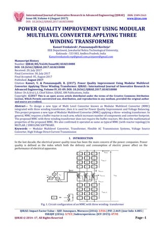
  • 1. International Journal of Innovative Research in Advanced Engineering (IJIRAE) ISSN: 2349-2163 Issue 08, Volume 4 (August 2017) www.ijirae.com DOI: 10.26562/IJIRAE.2017.AUAE10080 _________________________________________________________________________________________________ IJIRAE: Impact Factor Value – SJIF: Innospace, Morocco (2016): 3.916 | PIF: 2.469 | Jour Info: 4.085 | ISRAJIF (2016): 3.715 | Indexcopernicus: (ICV 2015): 47.91 IJIRAE © 2014- 17, All Rights Reserved Page -1 POWER QUALITY IMPROVEMENT USING MODULAR MULTILEVEL CONVERTER APPLYING THREE WINDING TRANSFORMER Kanuri Venkatesh1, Ponasanapalli Raviteja2 EEE Department, Jawaharlal Nehru Technological University, Kakinada - 533 003, Andhra Pradesh, India Kanurivenkatesh.vsp@gmail.com,p.tejaeee@gmail.com Manuscript History Number: IJIRAE/RS/Vol.04/Issue08/AUAE10080 DOI: 10.26562/IJIRAE.2017.AUAE10080 Received: 20, July 2017 Final Correction: 30, July 2017 Final Accepted: 05, August 2017 Published: August 2017 Citation: Kanuri, V. & Ponasanapalli, R. (2017). Power Quality Improvement Using Modular Multilevel Converter Applying Three Winding Transformer. IJIRAE:: International Journal of Innovative Research in Advanced Engineering, Volume IV, 01-09. DOI: 10.26562/IJIRAE.2017.AUAE10080 Editor: Dr.A.Arul L.S, Chief Editor, IJIRAE, AM Publications, India Copyright: ©2017 This is an open access article distributed under the terms of the Creative Commons Attribution License, Which Permits unrestricted use, distribution, and reproduction in any medium, provided the original author and source are credited. Abstract— To design a new type of Multi Level Converter known as Modular Multilevel Converter (MMC) integrated with three winding transformer, then it is used for Power Quality Improvement and Voltage Balancing. This project proposes a new type of Modular Multilevel Converter (MMC) applying a three- winding transformer. In general, MMC requires a buffer reactor in each arm, which increases number of components and converter footprint. The proposed MMC with three winding transformer does not require the buffer reactors. We describe mathematical properties of the proposed MMC. We also confirmed it operated as same as typical MMC (with reactor topology) In MATLAB / SIMULINK SOFTWARE. Keywords — Modular Multilevel Converter, Transformer, Flexible AC Transmission Systems, Voltage Source Converter, High Voltage Direct Current Transmission I. INTRODUCTION In the last decade, the electrical power quality issue has been the main concern of the power companies. Power quality is defined as the index which both the delivery and consumption of electric power affect on the performance of electrical apparatus. Fig. 1. Circuit configuration of an MMC with three winding- transformer
  • 2. International Journal of Innovative Research in Advanced Engineering (IJIRAE) ISSN: 2349-2163 Issue 08, Volume 4 (August 2017) www.ijirae.com DOI: 10.26562/IJIRAE.2017.AUAE10080 _________________________________________________________________________________________________ IJIRAE: Impact Factor Value – SJIF: Innospace, Morocco (2016): 3.916 | PIF: 2.469 | Jour Info: 4.085 | ISRAJIF (2016): 3.715 | Indexcopernicus: (ICV 2015): 47.91 IJIRAE © 2014- 17, All Rights Reserved Page -2 From a customer point of view, power quality problem can be defined as any problem is manifested on voltage, current, or frequency deviation that results in power failure. The power electronics progressive, especially in flexible alternating-current transmission system (FACTS) and custom power devices, affects power quality improvement. MMC consists of series half-bridge converter and does not require AC filters and can be generating the sine wave output AC terminal by reducing the switching frequency and number of levels of individual power devices. In this paper, we have to discuss that MMC has to eliminate the buffer reactor by reducing the number of components and we use the SVC (TCR) in the MMC also. So, we achieve the magnetic saturation and removing the lower cost. By applying three winding transformer the voltage and current equations are derived analytically. II. PROBLEM FORMULATION A. Topology of modular multilevel converter: The cascaded half bridge converter consists of three winding- transformer and the primary winding is connected to the AC grid. The upper and lower arm of each leg is connected to the secondary and tertiary windings of the converter. The two windings of secondary and tertiary is connected to the center of each leg and reverse direction, negative side of each winding is connected with each other. The upper and lower arm of the MMC consists of two components i.e; common component and other is distinct component. The magneto motive force of secondary and tertiary winding of the common component of the reverse direction and should be cancelled. Generally, the arm reactor of leakage inductance behaves like secondary and tertiary windings of the transformer. Moreover, the DC link of the neutral point should be connected to symmetrical monopole applying the HVDC transmission system. B. Description of 3- winding transformer: In this paper, we discuss analytically and mathematically of a three-winding transformer and shows flux flow of the transformer. The magnetic path of the iron core of each winding interlinks between individual windings. Leakage flux penetrates not only flux but also individual windings. Therefore, number of flux linkage of each winding Nps  ,, is given by equation (1).                                                     N P S NNN PPP SSS lN lP lS N P S N P S NNN NNN NNN N N N          00 00 00 (1) Where, Nps ,, are main flux, NPs 1,1,1 are leakage flux, NpsN ,, are number turns of each winding. When we added R to the magnetic circuit of the magnetic resistance of the main flux in the iron core, of each winding is expressed by (2), using the line current is, and the winding current ip, iN..                                              NNppNssN NNpppssp NNsppsss lN lP lS N P S N P S iNiNNiNN iNNiNiNN iNNiNNiN R N N N 2 2 2 /1 00 00 00       (2) is iP iN Vs VcP VcN Ns NP NN Primary winding Secondary winding Tertiary winding ɸs ɸP ɸN ɸ1s ɸ1P ɸ1N Fig.2. Flux flow of three winding transformer
  • 3. International Journal of Innovative Research in Advanced Engineering (IJIRAE) ISSN: 2349-2163 Issue 08, Volume 4 (August 2017) www.ijirae.com DOI: 10.26562/IJIRAE.2017.AUAE10080 _________________________________________________________________________________________________ IJIRAE: Impact Factor Value – SJIF: Innospace, Morocco (2016): 3.916 | PIF: 2.469 | Jour Info: 4.085 | ISRAJIF (2016): 3.715 | Indexcopernicus: (ICV 2015): 47.91 IJIRAE © 2014- 17, All Rights Reserved Page -3 The magnetic resistance of each winding of self and mutual inductance depends on number of windings by equation (3). R N L R N L R N L N N p P s S 2 2 2    , R NN M R NN M R NN M Np pN Ns sN ps sP    (3) Leakage flux depends on the leakage inductance and winding current. Accordingly, equation (2) is convert to equation (4) using equation (3).                                   N P S NNpNsN pNppsP sNsPss N p s i i i LlMM MLlM MMLl    (4) Relation between the voltage and winding current is obtained by equation (4).                                   N P S NNpNsN pNppsP sNsPss N p s i i i LlMM MLlM MMLl dt d v v v (5) By introducing, transformation ratio nsp and nsn of each mutual-inductance are changed excitation inductance by equation (6). N P PN N S sN P S sP N N n N N n N N n  ,, (6) C. Applying the transformer to MMC: In this paper, we applying the voltage and current equations of the transformer to MMC model of the equivalent circuit of the model (fig 1) . The upper arm current and lower arm current can be obtained by common current component and distinct current component. The common current and distinct current component is determined as icir, idef as equation (7). Therefore, lower arm current iN and upper arm current ip is defined as equation (8).   Npdef Npcir iii iii   2 1 (7) defcirN defcirp iii iii 2 1 2 1   (8) Using the three winding transformer of voltage and current equations of the common current component icir and distinct current component idef is given by equation (9).                                             defcir defcir s NNNpNNsN P PN PPPsP s sN s sp ss N P S ii ii i LlLnLn L n LlLn L n L n Ll dt d v v v 1 11 (9)
  • 4. International Journal of Innovative Research in Advanced Engineering (IJIRAE) ISSN: 2349-2163 Issue 08, Volume 4 (August 2017) www.ijirae.com DOI: 10.26562/IJIRAE.2017.AUAE10080 _________________________________________________________________________________________________ IJIRAE: Impact Factor Value – SJIF: Innospace, Morocco (2016): 3.916 | PIF: 2.469 | Jour Info: 4.085 | ISRAJIF (2016): 3.715 | Indexcopernicus: (ICV 2015): 47.91 IJIRAE © 2014- 17, All Rights Reserved Page -4 Now, the transformation ratio of primary to tertiary nsn and primary to secondary nsp are made equal to n. Therefore, the leakage inductance of tertiary winding IN and secondary winding IP are made equal to l. The equivalent circuit of three winding transformer is given by, Sv Si Sl SL SN N defi l Pi Pv Nv Nil Ideal transformer Fig.3. Equivalent circuit of three winding transformer The equivalent circuit of the three -winding transformer is shown in figure 3. It consists of ideal transformer and parallel connected to the primary leakage inductance ls, the excitation inductance Ls, of the secondary side of ideal transformer. An MMC consists of cascaded converter of switching frequency and should be higher than output voltage; and should be changed by variable voltage source. D. AC side current of the MMC: In this paper, AC side current of the MMC is defined. The three phase AC line voltage and AC line current is vs(r,s,t) and is(r,s,t). The voltage and current equation of primary side is given by equation (10).                                 t s r st ss sr s st ss sr v v v n i i i dt d l v v v sec_ sec_ sec_ (10) Where, vsec(r,s,t) is secondary voltage of ideal transformer. The ideal transformer of secondary voltage is given by equation (11), and it is followed by equation (11) to equation (12).         2 _sec def cirnparmpN i i dt d lvvvv        2 _ def cirnNarm i i dt d lvv (11) Where, MMC of DC link voltage is VPN. The neutral point voltage Vn of each transformer is connecting between negative side of DC link, varm_p, varm_N are total output voltage of each cells in each arm.        defnParmNarmPN i dt d lvvvvv 2 2 1 __sec (12) Now, the each transformer of neutral point vn of DC link is same voltage and secondary voltage is followed by (13).        defParmNarm i dt d lvvv __sec 2 1 (13) Generally, the primary side and secondary side of the transformer of an excitation inductance of a transformer is approximately equal.
  • 5. International Journal of Innovative Research in Advanced Engineering (IJIRAE) ISSN: 2349-2163 Issue 08, Volume 4 (August 2017) www.ijirae.com DOI: 10.26562/IJIRAE.2017.AUAE10080 _________________________________________________________________________________________________ IJIRAE: Impact Factor Value – SJIF: Innospace, Morocco (2016): 3.916 | PIF: 2.469 | Jour Info: 4.085 | ISRAJIF (2016): 3.715 | Indexcopernicus: (ICV 2015): 47.91 IJIRAE © 2014- 17, All Rights Reserved Page -5                                      tparmtNarm sparmSNarm rparmrNarm st ss sr s st ss sr vv vv vv n i i i dt d lnl v v v ____ ____ ____ 2 2 1 2 (14) The subtraction of upper arm and lower arm is varm_N, and varm_p is defined by equation and is converted to dq component of AC line voltage using matrix transformation C.                         tparmtNarm sparmSNarm rparmrNarm ct cs cr vv vv vv n v v v ____ ____ ____ 2 (15) Where,                                                          cq cd ct cs cr sq sd st ss sr sq sd st ss sr v v C v v v i i C i i i v v C v v v ,, (16)                       ) 3 4 cos( ) 3 2 cos( sin ) 3 4 cos( ) 3 2 cos( cos     wt wt wt wt wt wt C (17) Finally, dq coordinates of AC line voltages by inverse transformation matrix C is obtained by,                     ) 3 4 cos( ) 3 4 cos( ) 3 2 cos( ) 3 2 cos( sin cos 3 21     wt wt wt wt wt wt C (18)              01 101 wC dt d C (19) The equivalent model of the transformer of AC line current of voltage of converter arm is given by equation (18). The upper and lower arm current of AC line current is same as MMC converter. The secondary and tertiary winding of leakage inductance is connected in parallel of AC line reactor. It can be operated as MMC with three winding transformer as same as typical MMC. E. DC side current of the MMC: In this paper, DC link side current of the MMC is defined. The voltage and current of the DC link current is given by equation (20). NNarmpparmpN i dt d lvi dt d lvv  __ (20) It consists of common current component icir and distinct current component idef of the arm current iP and iN is mentioned before paper. Using the voltage and current equations is expressed by (21). cirNarmparm def cirNarm def cirparmPN i dt d lvv i i dt d lv i i dt d lvv 2 22 __ __               (21) Finally, the common current component is determined by,  dtvvv l i NarmparmPNcir __ 2 1  (22)
  • 6. International Journal of Innovative Research in Advanced Engineering (IJIRAE) ISSN: 2349-2163 Issue 08, Volume 4 (August 2017) www.ijirae.com DOI: 10.26562/IJIRAE.2017.AUAE10080 _________________________________________________________________________________________________ IJIRAE: Impact Factor Value – SJIF: Innospace, Morocco (2016): 3.916 | PIF: 2.469 | Jour Info: 4.085 | ISRAJIF (2016): 3.715 | Indexcopernicus: (ICV 2015): 47.91 IJIRAE © 2014- 17, All Rights Reserved Page -6 2 n abc to dq conv.2 n 2 n        2 1 2 ln lw s        2 1 2 ln ls s        2 1 2 ln lw s        2 1 2 ln ls s dq to abc conv. rparmv __ rNarmv __ sparmv __ sNarmv __ tparmv __ tNarmv __ wt crv csv ctv cqv sqv cdv sdv sdi sqi sri ssi sti Fig.4. AC line current between voltages of converter arm The upper and lower arm of common current component carries DC link side converter. The secondary and tertiary windings of IP and IN of leakage inductance behaves buffer reactor. TABLE I - PARAMETERS OF THE MMC PROTOTYPE Meaning Value AC Voltage 200V, 50Hz DC Voltage 400V Power rating 10KVA Cell capacitor voltage 100V Number of cell in each arm 4 Switching frequency (individual devices) 1KHz Leakage inductance (primary winding) 1.95MH (15.3%Z) Leakage inductance (secondary, tertiary winding) 1.3MH (8.37%Z) Capacitance in each cells 3960uF Transformation ratio 115V (P)/127V (S,T) III.SIMULATION RESULTS AND DISCUSSION The parameters of the MMC as shown in the table 1, The AC grids of the prototype converter are connected to the DC lines. The experimentation of the normal transformer, its iron core of saturation magnetic density is 1.85[T] at 116% (233V, 50Hz) of rated voltage. The magnetic density of iron core is 1.59[T] and rated voltage is (200V, 50Hz). IV. DIRECTION POWER FLOW IS AC TO DC AND DC TO ACCONVERSION The experimental results of figure 5 shows in grid connected operation. In all results, capacitor voltages of each cell and sinusoidal waveforms of ac line current are obtained and balanced with each other. This is AC to DC conversion is obtained by varying the duty cycle in the control circuit. Duty cycle< 0.5 is varied in control circuit. Fig.5.When the direction power flow is AC to DC
  • 7. International Journal of Innovative Research in Advanced Engineering (IJIRAE) ISSN: 2349-2163 Issue 08, Volume 4 (August 2017) www.ijirae.com DOI: 10.26562/IJIRAE.2017.AUAE10080 _________________________________________________________________________________________________ IJIRAE: Impact Factor Value – SJIF: Innospace, Morocco (2016): 3.916 | PIF: 2.469 | Jour Info: 4.085 | ISRAJIF (2016): 3.715 | Indexcopernicus: (ICV 2015): 47.91 IJIRAE © 2014- 17, All Rights Reserved Page -7 This is DC to AC conversion is obtained by varying the duty cycle in the control circuit. Duty cycle > 0.5 is varied in control circuit. Fig.6. When the direction power flow is DC to AC V. REACTIVE POWER LAGGING AND LEADING OPERATION When the faults occurs in the power distribution, voltage and currents decreases and at that condition reactive power lagging operation is occurred. Fig.7. In reactive power lagging operation When the faults occur in the power distribution voltage and currents increases and at that condition reactive power leading operation is occurred. Fig.8. In reactive power leading operation
  • 8. International Journal of Innovative Research in Advanced Engineering (IJIRAE) ISSN: 2349-2163 Issue 08, Volume 4 (August 2017) www.ijirae.com DOI: 10.26562/IJIRAE.2017.AUAE10080 _________________________________________________________________________________________________ IJIRAE: Impact Factor Value – SJIF: Innospace, Morocco (2016): 3.916 | PIF: 2.469 | Jour Info: 4.085 | ISRAJIF (2016): 3.715 | Indexcopernicus: (ICV 2015): 47.91 IJIRAE © 2014- 17, All Rights Reserved Page -8 VI. POWER FLOW REVERSAL FROM CONVERTER 1 TO 2 AND 2 TO 1 This is power flow reversal from converter 1 to converter 2 is obtained by rectifier operation in the circuit during converter charging period. Fig.9. Power flow reversal from converter 1 to converter 2 This is power flow reversal from converter 2 to converter 1 is obtained by rectifier operation in the circuit during converter charging period. Fig.10. Power flow reversal from converter 2 to converter 1 VII. FAULT OPERATION WHEN 1 LINE TO GROUND AND 3 LINES TO GROUND It shows experimental results in fault operation through AC line fault and magnetic saturation does not appear by charging the AC line voltage. Fig.11. fault ride through operation when 1 line to ground fault
  • 9. International Journal of Innovative Research in Advanced Engineering (IJIRAE) ISSN: 2349-2163 Issue 08, Volume 4 (August 2017) www.ijirae.com DOI: 10.26562/IJIRAE.2017.AUAE10080 _________________________________________________________________________________________________ IJIRAE: Impact Factor Value – SJIF: Innospace, Morocco (2016): 3.916 | PIF: 2.469 | Jour Info: 4.085 | ISRAJIF (2016): 3.715 | Indexcopernicus: (ICV 2015): 47.91 IJIRAE © 2014- 17, All Rights Reserved Page -9 Fig.12. fault ride through operation when 3 lines to ground fault VIII. CONCLUSION The paper is successfully implemented using MATLAB/ simulink software. In these control technique 24 cells have been implemented by using this technique we can reduce the cost of the transformer and can improve the output efficiency. This paper introduces a new type of Modular Multilevel Converter applying a three -winding transformer. The topology can merge buffer reactors into a grid connected transformer. In future study the DC bias magnetism of the buffer reactor into a grid connected transformer and the MMC with three winding transformer does not require a special transformer. REFERENCES 1. Lesnicar. A, Marquardt. R, "A new modular voltage source inverter topology", EPE 2003, 105, 2003. 2. Lesnicar. A, Marquardt. R, "An innovative modular multilevel converter topology suitable for a wide power range," Power Tech Conference Proceedings, 2003 IEEE Bologna, vol. 3, 2003. 3. Hagiwara. M, Akagi. H, "Control and Experiment of Pulse width Modulated Modular Multilevel Converters," IEEE Trans. on Power Electronics, vol. 24, no. 7, pp. 1737-1746, 2009. 4. Antonopoulous. A, Angquist. Lennart, Nee. H.-P, "On dynamics and voltage control of the Modular Multilevel Converter", EPE2009,2009. 5. Angquist, L, Antonopoulos. A, Siemaszko. D, lives. K, Yasiladiotis. M, Nee. H.-P., "Inner control of Modular Multilevel Converters - An approach using open-loop estimation of stored energy", International Power Electoronics Conference 2010, pp.1579-1585, 2010. 6. Munch. P, Gorges. D, Izak. M, Liu. Steven, "Integrated Current Control, Energy Control and Energy Balancing of Modular Multilevel Converters," IECON 20l0s, pp. 150-155, 2010. 7. M. Pereira, A. Zenkner, M. Claus, "Characteristics and benefits of modular multilevel converters for FACTS," Cigre2010, B4 104 2010. 8. Saeedifard. M, Iravani. R, "Dynamic Performance of a Modular Multilevel Back-to-Back HVDC system, " IEEE Trans. on Power Delivery, vol. 25, no. 4, pp. 2903-2912, 2010. 9. K, Antonopoulos. A, Norrga. Staflan, Nee. H.-P, "Steady State Analysis of Interaction Between Harmonic Components of Arm and Line Quantities of Modular Multilevel Converters", IEEE transactions on Power Electronics, vol. 27, no. 1, pp.57-68, 2013 10. Arai. J, Murao. T, Karube. T, Takagi. K, Ibrahim. M, "Design and Operation of SVC for Voltage Support at Mussafah Substation in Abu Dhabi," PEDS 2005, vol. 2, pp. 1356-1360, 2005.