

Empfohlen
Weitere ähnliche Inhalte
Was ist angesagt?
Was ist angesagt? (20)
Andere mochten auch
Andere mochten auch (13)
Ähnlich wie Modified bicmos
Ähnlich wie Modified bicmos (20)
Mehr von Himanshu Shekhar
Kürzlich hochgeladen
Kürzlich hochgeladen (20)
Modified bicmos
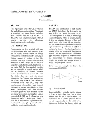
- 1. TERM PAPER OF ECE-563, NOVEMBER, 2014 BICMOS Himanshu Shekhar ABSTRACT This paper deals with BICMOS. First of all the need of transistor is justified. After this it is explained, the reason behind switching from vacuum tube to BJT to FET to BICMOS. Then simple working of BICMOS inverter working, its advantages, disadvantages and its application. I. INTRODUCTION The transistor is a three terminal, solid state electronic device. In a three terminal device we can control electric current or voltage between two of the terminals by applying an electric current or voltage to the third terminal. This three terminal character of the transistor is what allows us to make an amplifier for electrical signals, like the one in our radio. With the three-terminal transistor we can also make an electric switch, which can be controlled by another electrical switch. Before transistor vacuum tube were the device that were used for control conduction. But Vacuum tube had to warm up before they worked (and sometimes overheated when they did), they were unreliable and bulky and they used too much energy.so we moved toward BJT, to reduce power consumption, area and increase execution speed and more reliable. But for low power application and to reduce leakage current in BJT, FET was developed and most famous one is CMOS. From early 1980s BJT and CMOS are combined together to make a transistor that uses plus point of both to nullify the negative points of both. II. BICMOS BICMOS is a combination of both bipolar and CMOS that allows the designer to use both devices on a single integrated circuit. The development of BICMOS technology began in the early 1980s. In general, bipolar devices are attractive because of their high speed, better gain, better driving capability, and low wideband noise properties that allow high-quality analog performance. CMOS is particularly attractive for digital applications because of its low power and high packing density. Thus, the combination of both device types would not only lead to the replacement and improvement of existing integrated circuit, but would also provide access to design completely new circuits. Let’s take an example to know the importance of BICMOS. Fig.1 Cascade inverter As shown in Fig. 1 cascaded inverter is made to drive a bigger load than just a single inverter, and this has to do with speed. The problem is that a CMOS gate can drive a current proportionally to the width of its channel: so doubling the channel width, we
- 2. will be able to charge a capacitor twice as fast. If we double the channel width, it also double the input capacitance of the gate, so the stage before will take twice the time to drive the gate. So we need a gate which has the minimum possible input capacitance, while having as much as driving strength as possible. This is obtained cascading several inverters (the most elementary CMOS gate) with increasing channel width, so that the first has the required input capacitance and the last has the required driving strength. In comparison, bipolar junction transistors (BJTs) have more current driving capability, and hence, can overcome such speed bottlenecks using less silicon area. However, the power dissipation of bipolar logic gates is typically one or two orders of magnitude larger than that of comparable CMOS gates. Therefore, such all-bipolar high speed VLSI circuit are difficult to realize and require very elaborate heat-sink arrangements. An alternative solution to the problem of driving large capacitive loads can be provide by merging CMOS and bipolar devices (BICMOS) on chip Taking advantage of the low static power consumption of CMOS and the high current driving capability of the bipolar transistor during transients, the BICMOS configuration The BICMOS combination has significant advantages to offer, such as improved switching speed and less sensitivity with respect to the load capacitance. BICMOS logic circuits are not bipolar-intensive i.e. most logic operations are performed by conventional CMOS sub circuits, while the bipolar transistors are used only when high on-chip or off-chip drive capability is required. III. BASIC BICMOS CIRCUIT In BICMOS inverter as shown in Fig. 2, the complementary pMOS and nMOS transistors MP and MN supply base currents to the bipolar transistor and thus act as a trigger device for bipolar output stage configuration. Depending on the logic level of the input voltage, either MN or MP can be turned on in steady state, therefore assuring a fully complementary push pull operation mode for the two bipolar transistors. In this very simplistic configuration, configuration, two resistors are used to remove the base charge of the bipolar transistors when they are when they are in cut-off mode Fig. 2 Simple BICMOS inverter circuit with resistive base pull-down. The superiority of the BICMOS gate lies in the high current drive capability of the bipolar output transistors, the zero static power dissipation, and the high input impedance provided by the MOSFET configuration. To reduce the turn-off time of the bipolar transistors during switching, Two minimum-size nMOS transistors (MB1 and MB2) are usually added to provide the necessary base Discharge path, instead of the two resistors. As shown in Fig.3
- 3. Fig. 3 Conventional BICMOS inverter circuit with active base pull-down V. BICMOS INVERTER Consider first the output pull-up transient response, which starts with the input voltage abruptly falling from VOH to VOL at t = 0. The initial condition of the output node voltage is assumed to be VO, = VOH. The inverter circuit during this switching event is depicted in Fig.4, where the active (conducting) devices are highlighted. Fig. 4: BiCMOS inverter during transient output pull-up event. The active devices in thecircuit are highlighted (darker). As the input voltage drops, the pMOS transistor MP is turned on and starts operating in the saturation region. The nMOS transistors MN and MB 1 are turned off; thus, the lower "pull-down" part of the inverter circuit can be ignored except for the corresponding parasitic capacitances of the nMOS transistors and the bipolar transistor Q2. The base pull-down transistor MB2 is turned on, which effectively drains the excess base minority carrier charge of Q2 and assures that Q2 remains in cut-off mode. At the same time, MP is supplying the base current of Q1, which starts to charge up Cload with its emitter current. Now consider the output pull-down transient response, which starts with the input voltage abruptly rising from VOL to VOH at t = 0. The initial condition of the output node voltage is assumed to be Vout = VOL. The inverter circuit during this switching event is depicted in Fig.5, where the active (conducting) devices are highlighted. Fig. 5: BiCMOS inverter during a transient output pull-down event.The active devices in the circuit are highlighted (darker).
- 4. As the input voltage rises, the pMOS transistor MP is turned off and the nMOS Transistors MN and MB 1 are turned on. The bipolar pull-up transistor Q1 immediately ceases to conduct because its base current drops to zero, and MB 1 starts to remove the excess minority carrier base charge of Q1. The nMOS transistor MN operates initially in the saturation region and supplies the base current of the bipolar pull-down transistor Q2. IV. USES OF BICMOS TECHNOLOGY There have been two significant uses of BICMOS technology. One of the usages is in the design of the high- performance microprocessor unit (MPU) using the high driving capability of bipolar junction transistor because bipolar junction transistor has better transconductance. Comparing the gate delay time and load capacitance capability for same area design, BICMOS has a lower gate delay time than the CMOS at high load capacitive environment as illustrated in Fig 6. Fig. 6 CMOS vs BICMOS And second one is in the mixed signal circuit design, BICMOS design utilizes the excellent analog performance of the double poly self- aligned bipolar junction transistor V. BICMOS APPLICATION 1. In some applications (in which there is finite budget for power) the BICMOS speed performance is better than that of bipolar. 2. This technology is well suited for the intensive input/output applications. 3. The applications of BICMOS were initially in RISC microprocessors rather than traditional CISC microprocessors. 4. It can be used for sample and hold applications as it provides high impedance inputs. 5. This is also used in applications such as adders, mixers, ADC and DAC VI. CONCLUSION The most significant drawback of the BICMOS circuits lies in the increased fabrication process complexity more than that of CMOS. Apart from this it can be used as an alternate of the previous bipolar, ECL and CMOS in the market. VII. REFERENCE [1] http://www.nobelprize.org [2] http://blog.oscarliang.net/bjt-vs-mosfet [3] http:// www.elprocus.com [4] Digital Integrated Circuits, 2/E Jan M. Rabaey, University of California, Berkeley Anantha Chandrakasan, Massachusetts Institute of Technology, Cambridge Borivoje Nikolic, University of California, Berkeley. [5] CMOS Digital integrated Circuits Sung- Mo-Kang & Yusuf Leblebici 3rd 2003 Tata McGraw Hill