SlideShare ist ein Scribd-Unternehmen logo
1 von 16
A flywheel, as shown in Fig, consists of a rim at
which the major portion of the mass or weight of
flywheel is concentrated, a boss or hub for fixing
the flywheel on to the shaft and a number of arms
for supporting the rim on the hub.
The following types of stresses are induced in the
rim of a flywheel:
1. Tensile stress due to centrifugal force,
2. Tensile bending stress caused by the restraint
of the arms, and
3. The shrinkage stresses due to unequal rate of
cooling of casting. These stresses may be very
high but there is no easy method of determining.
This stress is taken care of by a factor of safety.
We shall now discuss the first two types of
stresses as follows:
The tensile stress in the rim due to the centrifugal force, assuming that the rim is
unstrained by the arms, is determined in a similar way as a thin cylinder subjected
to internal pressure.
Let b = Width of rim,
t = Thickness of rim,
A = Cross-sectional area of rim = b × t,
D = Mean diameter of flywheel
R = Mean radius of flywheel,
ρ = Density of flywheel material,
ω = Angular speed of flywheel,
v = Linear velocity of flywheel, and
σt = Tensile or hoop stress
Consider a small element of the rim as shown shaded
in Fig. 22.10. Let it subtends an angle δθ at the centre
of the flywheel.
Volume of the small element = A.R.δθ
Mass of the small element, dm = Volume × Density
= A.R.δθ.ρ = ρ.A.R.δθ
and centrifugal force on the element, dF = dm.ω².R
= ρ.A.R.δθ.ω².R = ρ.A.R².ω².δθ
Vertical component of dF = dF.sin θ = ρ.A.R².ω².δθ sin θ
Tensile bending stress caused by restraint of the arms
The tensile bending stress in the rim due to
the restraint of the arms is based on the
assumption that each portion of the rim
between a pair of arms behaves like a
beam fixed at both ends and uniformly
loaded, as shown in Fig. such that length
between fixed ends,
If the arms of a flywheel do not stretch at all and are placed very close together,
then centrifugal force will not set up stress in the rim. In other words, σt will be
zero. On the other hand, if the arms are stretched enough to allow free expansion
of the rim due to centrifugal action, there will be no restraint due to the arms, i.e.
σb will be zero.
It has been shown by G. Lanza that the arms of a flywheel stretch about ¾ th of
the amount necessary for free expansion. Therefore the total stress in the rim,
The areas of the turning moment diagram for one revolution of a multi-cylinder
engine with reference to the mean turning moment, below and above the line, are –
32, + 408, – 267, + 333, – 310, + 226, – 374, + 260 and – 244 mm². The scale for
abscissa and ordinate are: 1 mm = 2.4° and 1 mm = 650 N-m respectively. The mean
speed is 300 r.p.m. with a percentage speed fluctuation of ± 1.5%. If the hoop stress in
the material of the rim is not to exceed 5.6 MPa, determine the suitable diameter and
cross-section for the flywheel, assuming that the width is equal to 4 times the
thickness. The density of the material may be taken as 7200 kg / m³. Neglect the effect
of the boss and arms.
Every one practice the problems of Example 22.5 to 22.9
Stresses in Flywheel Arms
The following stresses are induced in the arms of a flywheel.
1. Tensile stress due to centrifugal force acting on the rim.
2. Bending stress due to the torque transmitted from the rim to the shaft or from
the shaft to the rim.
3. Shrinkage stresses due to unequal rate of cooling of casting. These stresses are
difficult to determine.
1. Tensile stress due to the centrifugal force
Due to the centrifugal force acting on the rim, the arms will be subjected to direct tensile
stress whose magnitude is same as discussed in the previous article.
∴ Tensile stress in the arms,
σt1 = 3/4 , σt = 3/4 ρ × v²
Bending stress due to the torque transmitted
Due to the torque transmitted from the rim to
the shaft or from the shaft to the rim, the arms
will be subjected to bending, because they are
required to carry the full torque load. In order to
find out the maximum bending moment on the
arms, it may be assumed as a centilever beam
fixed at the hub and carrying a concentrated
load at the free end of the rim as shown in Fig.
Let T = Maximum torque transmitted by the shaft,
R = Mean radius of the rim,
r = Radius of the hub,
n = Number of arms, and
Z = Section modulus for the cross-section of arms.
Design of Flywheel Arms
The cross-section of the arms is usually elliptical
with major axis as twice the minor axis, as shown
in Fig , and it is designed for the maximum
bending stress.
Let a1 = Major axis, and
b1 = Minor axis.
Notes:
1. The arms of the flywheel have a taper from the hub to the rim. The taper is about 20
mm per metre length of the arm for the major axis and 10 mm per metre length for the
minor axis.
2. The number of arms are usually 6. Sometimes the arms may be 8, 10 or 12 for very
large size flywheels.
3. The arms may be curved or straight. But straight arms are easy to cast and are
lighter.
4. Since arms are subjected to reversal of stresses, therefore a minimum factor of
safety 8 should be used. In some cases like punching machines and machines subjected
to severe shock, a factor of safety 15 may be used.
5. The smaller flywheels (less than 600 mm diameter) are not provided with arms.
They are made web type with holes in the web to facilitate handling.
Design of Shaft, Hub and Key

Weitere ähnliche Inhalte

Was ist angesagt?

1 Design of flywheel
1 Design of flywheel1 Design of flywheel
1 Design of flywheelDr.R. SELVAM
 
Numericals curved bar
Numericals curved barNumericals curved bar
Numericals curved barYatin Singh
 
6 shaft shafts subjected to fluctuating loads
6 shaft   shafts subjected to fluctuating loads6 shaft   shafts subjected to fluctuating loads
6 shaft shafts subjected to fluctuating loadsDr.R. SELVAM
 
Module 1 introduction to kinematics of machinery
Module 1 introduction to kinematics of machineryModule 1 introduction to kinematics of machinery
Module 1 introduction to kinematics of machinerytaruian
 
Velocity & acceleration diagrams
Velocity & acceleration diagramsVelocity & acceleration diagrams
Velocity & acceleration diagramssherin_ginige
 
ME6503 - DESIGN OF MACHINE ELEMENTS UNIT - II NOTES
ME6503 - DESIGN OF MACHINE ELEMENTS UNIT - II NOTESME6503 - DESIGN OF MACHINE ELEMENTS UNIT - II NOTES
ME6503 - DESIGN OF MACHINE ELEMENTS UNIT - II NOTESASHOK KUMAR RAJENDRAN
 
ME6601 - DESIGN OF TRANSMISSION SYSTEM NOTES AND QUESTION BANK
ME6601 - DESIGN OF TRANSMISSION SYSTEM NOTES AND QUESTION BANK ME6601 - DESIGN OF TRANSMISSION SYSTEM NOTES AND QUESTION BANK
ME6601 - DESIGN OF TRANSMISSION SYSTEM NOTES AND QUESTION BANK ASHOK KUMAR RAJENDRAN
 
Torsional vibrations
Torsional  vibrationsTorsional  vibrations
Torsional vibrationsM.D.Raj Kamal
 
Specific Speed of Turbine | Fluid Mechanics
Specific Speed of Turbine | Fluid MechanicsSpecific Speed of Turbine | Fluid Mechanics
Specific Speed of Turbine | Fluid MechanicsSatish Taji
 
Cam displacement diagram
Cam displacement diagramCam displacement diagram
Cam displacement diagramphysics101
 
Spur gear problem and solution
Spur gear   problem and solutionSpur gear   problem and solution
Spur gear problem and solutiondodi mulya
 

Was ist angesagt? (20)

1 Design of flywheel
1 Design of flywheel1 Design of flywheel
1 Design of flywheel
 
Numericals curved bar
Numericals curved barNumericals curved bar
Numericals curved bar
 
6 shaft shafts subjected to fluctuating loads
6 shaft   shafts subjected to fluctuating loads6 shaft   shafts subjected to fluctuating loads
6 shaft shafts subjected to fluctuating loads
 
Stress concentration
Stress concentrationStress concentration
Stress concentration
 
Module 1 introduction to kinematics of machinery
Module 1 introduction to kinematics of machineryModule 1 introduction to kinematics of machinery
Module 1 introduction to kinematics of machinery
 
Static Force Analysis
Static Force AnalysisStatic Force Analysis
Static Force Analysis
 
Velocity & acceleration diagrams
Velocity & acceleration diagramsVelocity & acceleration diagrams
Velocity & acceleration diagrams
 
Flywheel
FlywheelFlywheel
Flywheel
 
ME6503 - DESIGN OF MACHINE ELEMENTS UNIT - II NOTES
ME6503 - DESIGN OF MACHINE ELEMENTS UNIT - II NOTESME6503 - DESIGN OF MACHINE ELEMENTS UNIT - II NOTES
ME6503 - DESIGN OF MACHINE ELEMENTS UNIT - II NOTES
 
Torsion
TorsionTorsion
Torsion
 
Dynamometers
DynamometersDynamometers
Dynamometers
 
ME6601 - DESIGN OF TRANSMISSION SYSTEM NOTES AND QUESTION BANK
ME6601 - DESIGN OF TRANSMISSION SYSTEM NOTES AND QUESTION BANK ME6601 - DESIGN OF TRANSMISSION SYSTEM NOTES AND QUESTION BANK
ME6601 - DESIGN OF TRANSMISSION SYSTEM NOTES AND QUESTION BANK
 
Worm gears
Worm gearsWorm gears
Worm gears
 
Torsional vibrations
Torsional  vibrationsTorsional  vibrations
Torsional vibrations
 
Thin and thick cylinders
Thin and thick cylindersThin and thick cylinders
Thin and thick cylinders
 
Specific Speed of Turbine | Fluid Mechanics
Specific Speed of Turbine | Fluid MechanicsSpecific Speed of Turbine | Fluid Mechanics
Specific Speed of Turbine | Fluid Mechanics
 
Balancing of rotating masses
Balancing of rotating massesBalancing of rotating masses
Balancing of rotating masses
 
Cam displacement diagram
Cam displacement diagramCam displacement diagram
Cam displacement diagram
 
Whirling of shaft
Whirling of shaftWhirling of shaft
Whirling of shaft
 
Spur gear problem and solution
Spur gear   problem and solutionSpur gear   problem and solution
Spur gear problem and solution
 

Ähnlich wie Stresses in flywheel rim.pptx

Clutches ,Brakes and Dynamometer
Clutches ,Brakes and DynamometerClutches ,Brakes and Dynamometer
Clutches ,Brakes and Dynamometernmahi96
 
Torsional and bending stresses in machine parts
Torsional and bending stresses in machine partsTorsional and bending stresses in machine parts
Torsional and bending stresses in machine partsMohamed Mohamed El-Sayed
 
3 shaft stress in shafts
3 shaft   stress in shafts3 shaft   stress in shafts
3 shaft stress in shaftsDr.R. SELVAM
 
CHAPTER THREE.pptx
CHAPTER THREE.pptxCHAPTER THREE.pptx
CHAPTER THREE.pptxhaymanot16
 
CLUTCH.pptx, type of clutch and design clutch
CLUTCH.pptx, type of clutch and design clutchCLUTCH.pptx, type of clutch and design clutch
CLUTCH.pptx, type of clutch and design clutchhaymanot16
 
Torsion of circular shafts
Torsion of circular shaftsTorsion of circular shafts
Torsion of circular shaftsYatin Singh
 
SPRING Design & Design parameters details
SPRING Design & Design parameters detailsSPRING Design & Design parameters details
SPRING Design & Design parameters detailsDeepakRamachandra2
 
Presentation on module 2 lecture 2.pptx
Presentation on module 2 lecture 2.pptxPresentation on module 2 lecture 2.pptx
Presentation on module 2 lecture 2.pptxAnantaKumarNandi
 
Elemen Mesin 1 - Bantalan
Elemen Mesin 1 - BantalanElemen Mesin 1 - Bantalan
Elemen Mesin 1 - BantalanCharis Muhammad
 
DMM I Unit III Bolted Joints 25-05-2021.pptx
DMM I Unit III Bolted Joints 25-05-2021.pptxDMM I Unit III Bolted Joints 25-05-2021.pptx
DMM I Unit III Bolted Joints 25-05-2021.pptxVenkateswarlu Velisala
 
1-Machine design - Stresses in Machine Members (2) - Copy.pptx
1-Machine design - Stresses in Machine Members (2) - Copy.pptx1-Machine design - Stresses in Machine Members (2) - Copy.pptx
1-Machine design - Stresses in Machine Members (2) - Copy.pptxssuser2e7793
 
Advanced structures - wing section, beams, bending, shear flow and shear center
Advanced structures - wing section, beams, bending, shear flow and shear centerAdvanced structures - wing section, beams, bending, shear flow and shear center
Advanced structures - wing section, beams, bending, shear flow and shear centerRohan M Ganapathy
 

Ähnlich wie Stresses in flywheel rim.pptx (20)

Mm210(2)
Mm210(2)Mm210(2)
Mm210(2)
 
Unit 6: Bending and shear Stresses in beams
Unit 6: Bending and shear Stresses in beamsUnit 6: Bending and shear Stresses in beams
Unit 6: Bending and shear Stresses in beams
 
Clutches ,Brakes and Dynamometer
Clutches ,Brakes and DynamometerClutches ,Brakes and Dynamometer
Clutches ,Brakes and Dynamometer
 
Torsional and bending stresses in machine parts
Torsional and bending stresses in machine partsTorsional and bending stresses in machine parts
Torsional and bending stresses in machine parts
 
3 shaft stress in shafts
3 shaft   stress in shafts3 shaft   stress in shafts
3 shaft stress in shafts
 
CHAPTER THREE.pptx
CHAPTER THREE.pptxCHAPTER THREE.pptx
CHAPTER THREE.pptx
 
CLUTCH.pptx, type of clutch and design clutch
CLUTCH.pptx, type of clutch and design clutchCLUTCH.pptx, type of clutch and design clutch
CLUTCH.pptx, type of clutch and design clutch
 
Torsion of circular shafts
Torsion of circular shaftsTorsion of circular shafts
Torsion of circular shafts
 
Levers
LeversLevers
Levers
 
SPRING Design & Design parameters details
SPRING Design & Design parameters detailsSPRING Design & Design parameters details
SPRING Design & Design parameters details
 
Me211 2
Me211 2Me211 2
Me211 2
 
Presentation on module 2 lecture 2.pptx
Presentation on module 2 lecture 2.pptxPresentation on module 2 lecture 2.pptx
Presentation on module 2 lecture 2.pptx
 
Plastic bottle analysis
Plastic bottle analysisPlastic bottle analysis
Plastic bottle analysis
 
Elemen Mesin 1 - Bantalan
Elemen Mesin 1 - BantalanElemen Mesin 1 - Bantalan
Elemen Mesin 1 - Bantalan
 
Unit 3 machines
Unit 3 machines Unit 3 machines
Unit 3 machines
 
DMM I Unit III Bolted Joints 25-05-2021.pptx
DMM I Unit III Bolted Joints 25-05-2021.pptxDMM I Unit III Bolted Joints 25-05-2021.pptx
DMM I Unit III Bolted Joints 25-05-2021.pptx
 
Necking
NeckingNecking
Necking
 
1-Machine design - Stresses in Machine Members (2) - Copy.pptx
1-Machine design - Stresses in Machine Members (2) - Copy.pptx1-Machine design - Stresses in Machine Members (2) - Copy.pptx
1-Machine design - Stresses in Machine Members (2) - Copy.pptx
 
Advanced structures - wing section, beams, bending, shear flow and shear center
Advanced structures - wing section, beams, bending, shear flow and shear centerAdvanced structures - wing section, beams, bending, shear flow and shear center
Advanced structures - wing section, beams, bending, shear flow and shear center
 
Mm210(8)
Mm210(8)Mm210(8)
Mm210(8)
 

Mehr von HarikumarA4

Belt Drives_2.pdf
Belt Drives_2.pdfBelt Drives_2.pdf
Belt Drives_2.pdfHarikumarA4
 
unit2designofshaft-170719110901 (1) (1).pptx
unit2designofshaft-170719110901 (1) (1).pptxunit2designofshaft-170719110901 (1) (1).pptx
unit2designofshaft-170719110901 (1) (1).pptxHarikumarA4
 
Belt Drives_1.pptx
Belt Drives_1.pptxBelt Drives_1.pptx
Belt Drives_1.pptxHarikumarA4
 
BRAKE_SYSTEM.pptx
BRAKE_SYSTEM.pptxBRAKE_SYSTEM.pptx
BRAKE_SYSTEM.pptxHarikumarA4
 
V-belt Drives.pptx
V-belt Drives.pptxV-belt Drives.pptx
V-belt Drives.pptxHarikumarA4
 
Sliding-Contact-Bearings.ppt
Sliding-Contact-Bearings.pptSliding-Contact-Bearings.ppt
Sliding-Contact-Bearings.pptHarikumarA4
 
pp-chapter 7.ppt
pp-chapter 7.pptpp-chapter 7.ppt
pp-chapter 7.pptHarikumarA4
 
engineering-graphics.pdf
engineering-graphics.pdfengineering-graphics.pdf
engineering-graphics.pdfHarikumarA4
 

Mehr von HarikumarA4 (11)

Belt Drives_2.pdf
Belt Drives_2.pdfBelt Drives_2.pdf
Belt Drives_2.pdf
 
unit2designofshaft-170719110901 (1) (1).pptx
unit2designofshaft-170719110901 (1) (1).pptxunit2designofshaft-170719110901 (1) (1).pptx
unit2designofshaft-170719110901 (1) (1).pptx
 
99999599.pptx
99999599.pptx99999599.pptx
99999599.pptx
 
Belt Drives_1.pptx
Belt Drives_1.pptxBelt Drives_1.pptx
Belt Drives_1.pptx
 
PPT- CDT-8.pptx
PPT- CDT-8.pptxPPT- CDT-8.pptx
PPT- CDT-8.pptx
 
clutch.ppt
clutch.pptclutch.ppt
clutch.ppt
 
BRAKE_SYSTEM.pptx
BRAKE_SYSTEM.pptxBRAKE_SYSTEM.pptx
BRAKE_SYSTEM.pptx
 
V-belt Drives.pptx
V-belt Drives.pptxV-belt Drives.pptx
V-belt Drives.pptx
 
Sliding-Contact-Bearings.ppt
Sliding-Contact-Bearings.pptSliding-Contact-Bearings.ppt
Sliding-Contact-Bearings.ppt
 
pp-chapter 7.ppt
pp-chapter 7.pptpp-chapter 7.ppt
pp-chapter 7.ppt
 
engineering-graphics.pdf
engineering-graphics.pdfengineering-graphics.pdf
engineering-graphics.pdf
 

Kürzlich hochgeladen

Class 1 | NFPA 72 | Overview Fire Alarm System
Class 1 | NFPA 72 | Overview Fire Alarm SystemClass 1 | NFPA 72 | Overview Fire Alarm System
Class 1 | NFPA 72 | Overview Fire Alarm Systemirfanmechengr
 
Indian Dairy Industry Present Status and.ppt
Indian Dairy Industry Present Status and.pptIndian Dairy Industry Present Status and.ppt
Indian Dairy Industry Present Status and.pptMadan Karki
 
multiple access in wireless communication
multiple access in wireless communicationmultiple access in wireless communication
multiple access in wireless communicationpanditadesh123
 
Crushers to screens in aggregate production
Crushers to screens in aggregate productionCrushers to screens in aggregate production
Crushers to screens in aggregate productionChinnuNinan
 
UNIT III ANALOG ELECTRONICS (BASIC ELECTRONICS)
UNIT III ANALOG ELECTRONICS (BASIC ELECTRONICS)UNIT III ANALOG ELECTRONICS (BASIC ELECTRONICS)
UNIT III ANALOG ELECTRONICS (BASIC ELECTRONICS)Dr SOUNDIRARAJ N
 
Earthing details of Electrical Substation
Earthing details of Electrical SubstationEarthing details of Electrical Substation
Earthing details of Electrical Substationstephanwindworld
 
Configuration of IoT devices - Systems managament
Configuration of IoT devices - Systems managamentConfiguration of IoT devices - Systems managament
Configuration of IoT devices - Systems managamentBharaniDharan195623
 
Engineering Drawing section of solid
Engineering Drawing     section of solidEngineering Drawing     section of solid
Engineering Drawing section of solidnamansinghjarodiya
 
IVE Industry Focused Event - Defence Sector 2024
IVE Industry Focused Event - Defence Sector 2024IVE Industry Focused Event - Defence Sector 2024
IVE Industry Focused Event - Defence Sector 2024Mark Billinghurst
 
Arduino_CSE ece ppt for working and principal of arduino.ppt
Arduino_CSE ece ppt for working and principal of arduino.pptArduino_CSE ece ppt for working and principal of arduino.ppt
Arduino_CSE ece ppt for working and principal of arduino.pptSAURABHKUMAR892774
 
Transport layer issues and challenges - Guide
Transport layer issues and challenges - GuideTransport layer issues and challenges - Guide
Transport layer issues and challenges - GuideGOPINATHS437943
 
Internet of things -Arshdeep Bahga .pptx
Internet of things -Arshdeep Bahga .pptxInternet of things -Arshdeep Bahga .pptx
Internet of things -Arshdeep Bahga .pptxVelmuruganTECE
 
Software and Systems Engineering Standards: Verification and Validation of Sy...
Software and Systems Engineering Standards: Verification and Validation of Sy...Software and Systems Engineering Standards: Verification and Validation of Sy...
Software and Systems Engineering Standards: Verification and Validation of Sy...VICTOR MAESTRE RAMIREZ
 
Risk Management in Engineering Construction Project
Risk Management in Engineering Construction ProjectRisk Management in Engineering Construction Project
Risk Management in Engineering Construction ProjectErbil Polytechnic University
 
Work Experience-Dalton Park.pptxfvvvvvvv
Work Experience-Dalton Park.pptxfvvvvvvvWork Experience-Dalton Park.pptxfvvvvvvv
Work Experience-Dalton Park.pptxfvvvvvvvLewisJB
 
DM Pillar Training Manual.ppt will be useful in deploying TPM in project
DM Pillar Training Manual.ppt will be useful in deploying TPM in projectDM Pillar Training Manual.ppt will be useful in deploying TPM in project
DM Pillar Training Manual.ppt will be useful in deploying TPM in projectssuserb6619e
 
Virtual memory management in Operating System
Virtual memory management in Operating SystemVirtual memory management in Operating System
Virtual memory management in Operating SystemRashmi Bhat
 
System Simulation and Modelling with types and Event Scheduling
System Simulation and Modelling with types and Event SchedulingSystem Simulation and Modelling with types and Event Scheduling
System Simulation and Modelling with types and Event SchedulingBootNeck1
 

Kürzlich hochgeladen (20)

Class 1 | NFPA 72 | Overview Fire Alarm System
Class 1 | NFPA 72 | Overview Fire Alarm SystemClass 1 | NFPA 72 | Overview Fire Alarm System
Class 1 | NFPA 72 | Overview Fire Alarm System
 
Indian Dairy Industry Present Status and.ppt
Indian Dairy Industry Present Status and.pptIndian Dairy Industry Present Status and.ppt
Indian Dairy Industry Present Status and.ppt
 
multiple access in wireless communication
multiple access in wireless communicationmultiple access in wireless communication
multiple access in wireless communication
 
Crushers to screens in aggregate production
Crushers to screens in aggregate productionCrushers to screens in aggregate production
Crushers to screens in aggregate production
 
UNIT III ANALOG ELECTRONICS (BASIC ELECTRONICS)
UNIT III ANALOG ELECTRONICS (BASIC ELECTRONICS)UNIT III ANALOG ELECTRONICS (BASIC ELECTRONICS)
UNIT III ANALOG ELECTRONICS (BASIC ELECTRONICS)
 
Design and analysis of solar grass cutter.pdf
Design and analysis of solar grass cutter.pdfDesign and analysis of solar grass cutter.pdf
Design and analysis of solar grass cutter.pdf
 
Earthing details of Electrical Substation
Earthing details of Electrical SubstationEarthing details of Electrical Substation
Earthing details of Electrical Substation
 
POWER SYSTEMS-1 Complete notes examples
POWER SYSTEMS-1 Complete notes  examplesPOWER SYSTEMS-1 Complete notes  examples
POWER SYSTEMS-1 Complete notes examples
 
Configuration of IoT devices - Systems managament
Configuration of IoT devices - Systems managamentConfiguration of IoT devices - Systems managament
Configuration of IoT devices - Systems managament
 
Engineering Drawing section of solid
Engineering Drawing     section of solidEngineering Drawing     section of solid
Engineering Drawing section of solid
 
IVE Industry Focused Event - Defence Sector 2024
IVE Industry Focused Event - Defence Sector 2024IVE Industry Focused Event - Defence Sector 2024
IVE Industry Focused Event - Defence Sector 2024
 
Arduino_CSE ece ppt for working and principal of arduino.ppt
Arduino_CSE ece ppt for working and principal of arduino.pptArduino_CSE ece ppt for working and principal of arduino.ppt
Arduino_CSE ece ppt for working and principal of arduino.ppt
 
Transport layer issues and challenges - Guide
Transport layer issues and challenges - GuideTransport layer issues and challenges - Guide
Transport layer issues and challenges - Guide
 
Internet of things -Arshdeep Bahga .pptx
Internet of things -Arshdeep Bahga .pptxInternet of things -Arshdeep Bahga .pptx
Internet of things -Arshdeep Bahga .pptx
 
Software and Systems Engineering Standards: Verification and Validation of Sy...
Software and Systems Engineering Standards: Verification and Validation of Sy...Software and Systems Engineering Standards: Verification and Validation of Sy...
Software and Systems Engineering Standards: Verification and Validation of Sy...
 
Risk Management in Engineering Construction Project
Risk Management in Engineering Construction ProjectRisk Management in Engineering Construction Project
Risk Management in Engineering Construction Project
 
Work Experience-Dalton Park.pptxfvvvvvvv
Work Experience-Dalton Park.pptxfvvvvvvvWork Experience-Dalton Park.pptxfvvvvvvv
Work Experience-Dalton Park.pptxfvvvvvvv
 
DM Pillar Training Manual.ppt will be useful in deploying TPM in project
DM Pillar Training Manual.ppt will be useful in deploying TPM in projectDM Pillar Training Manual.ppt will be useful in deploying TPM in project
DM Pillar Training Manual.ppt will be useful in deploying TPM in project
 
Virtual memory management in Operating System
Virtual memory management in Operating SystemVirtual memory management in Operating System
Virtual memory management in Operating System
 
System Simulation and Modelling with types and Event Scheduling
System Simulation and Modelling with types and Event SchedulingSystem Simulation and Modelling with types and Event Scheduling
System Simulation and Modelling with types and Event Scheduling
 

Stresses in flywheel rim.pptx

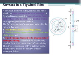
  • 1. A flywheel, as shown in Fig, consists of a rim at which the major portion of the mass or weight of flywheel is concentrated, a boss or hub for fixing the flywheel on to the shaft and a number of arms for supporting the rim on the hub. The following types of stresses are induced in the rim of a flywheel: 1. Tensile stress due to centrifugal force, 2. Tensile bending stress caused by the restraint of the arms, and 3. The shrinkage stresses due to unequal rate of cooling of casting. These stresses may be very high but there is no easy method of determining. This stress is taken care of by a factor of safety. We shall now discuss the first two types of stresses as follows:
  • 2. The tensile stress in the rim due to the centrifugal force, assuming that the rim is unstrained by the arms, is determined in a similar way as a thin cylinder subjected to internal pressure. Let b = Width of rim, t = Thickness of rim, A = Cross-sectional area of rim = b × t, D = Mean diameter of flywheel R = Mean radius of flywheel, ρ = Density of flywheel material, ω = Angular speed of flywheel, v = Linear velocity of flywheel, and σt = Tensile or hoop stress
  • 3. Consider a small element of the rim as shown shaded in Fig. 22.10. Let it subtends an angle δθ at the centre of the flywheel. Volume of the small element = A.R.δθ Mass of the small element, dm = Volume × Density = A.R.δθ.ρ = ρ.A.R.δθ and centrifugal force on the element, dF = dm.ω².R = ρ.A.R.δθ.ω².R = ρ.A.R².ω².δθ Vertical component of dF = dF.sin θ = ρ.A.R².ω².δθ sin θ
  • 4.
  • 5. Tensile bending stress caused by restraint of the arms The tensile bending stress in the rim due to the restraint of the arms is based on the assumption that each portion of the rim between a pair of arms behaves like a beam fixed at both ends and uniformly loaded, as shown in Fig. such that length between fixed ends,
  • 6. If the arms of a flywheel do not stretch at all and are placed very close together, then centrifugal force will not set up stress in the rim. In other words, σt will be zero. On the other hand, if the arms are stretched enough to allow free expansion of the rim due to centrifugal action, there will be no restraint due to the arms, i.e. σb will be zero. It has been shown by G. Lanza that the arms of a flywheel stretch about ¾ th of the amount necessary for free expansion. Therefore the total stress in the rim,
  • 7. The areas of the turning moment diagram for one revolution of a multi-cylinder engine with reference to the mean turning moment, below and above the line, are – 32, + 408, – 267, + 333, – 310, + 226, – 374, + 260 and – 244 mm². The scale for abscissa and ordinate are: 1 mm = 2.4° and 1 mm = 650 N-m respectively. The mean speed is 300 r.p.m. with a percentage speed fluctuation of ± 1.5%. If the hoop stress in the material of the rim is not to exceed 5.6 MPa, determine the suitable diameter and cross-section for the flywheel, assuming that the width is equal to 4 times the thickness. The density of the material may be taken as 7200 kg / m³. Neglect the effect of the boss and arms.
  • 8.
  • 9.
  • 10. Every one practice the problems of Example 22.5 to 22.9
  • 11. Stresses in Flywheel Arms The following stresses are induced in the arms of a flywheel. 1. Tensile stress due to centrifugal force acting on the rim. 2. Bending stress due to the torque transmitted from the rim to the shaft or from the shaft to the rim. 3. Shrinkage stresses due to unequal rate of cooling of casting. These stresses are difficult to determine. 1. Tensile stress due to the centrifugal force Due to the centrifugal force acting on the rim, the arms will be subjected to direct tensile stress whose magnitude is same as discussed in the previous article. ∴ Tensile stress in the arms, σt1 = 3/4 , σt = 3/4 ρ × v²
  • 12. Bending stress due to the torque transmitted Due to the torque transmitted from the rim to the shaft or from the shaft to the rim, the arms will be subjected to bending, because they are required to carry the full torque load. In order to find out the maximum bending moment on the arms, it may be assumed as a centilever beam fixed at the hub and carrying a concentrated load at the free end of the rim as shown in Fig. Let T = Maximum torque transmitted by the shaft, R = Mean radius of the rim, r = Radius of the hub, n = Number of arms, and Z = Section modulus for the cross-section of arms.
  • 13.
  • 14. Design of Flywheel Arms The cross-section of the arms is usually elliptical with major axis as twice the minor axis, as shown in Fig , and it is designed for the maximum bending stress. Let a1 = Major axis, and b1 = Minor axis.
  • 15. Notes: 1. The arms of the flywheel have a taper from the hub to the rim. The taper is about 20 mm per metre length of the arm for the major axis and 10 mm per metre length for the minor axis. 2. The number of arms are usually 6. Sometimes the arms may be 8, 10 or 12 for very large size flywheels. 3. The arms may be curved or straight. But straight arms are easy to cast and are lighter. 4. Since arms are subjected to reversal of stresses, therefore a minimum factor of safety 8 should be used. In some cases like punching machines and machines subjected to severe shock, a factor of safety 15 may be used. 5. The smaller flywheels (less than 600 mm diameter) are not provided with arms. They are made web type with holes in the web to facilitate handling.
  • 16. Design of Shaft, Hub and Key