SlideShare a Scribd company logo
1 of 119
Download to read offline
Mr. Geoffrey Allen Wardle. MSc. MSc. ATDA Airframe Design Study 2012-2020
By Mr. GEOFFREY ALLEN WARDLE. MSc. MSc. MRAeS. CEng. Snr MAIAA.
ATDA STUDY PRESENTATION PART: - 1 (AIRFRAME MANUFACTURING
TECHNOLOGY OVERVIEW AND CONCEPT AIRCRAFT ANALYSIS).
Mr. Geoffrey Allen Wardle. MSc. MSc. ATDA Airframe Design Study 2012-2020
This presentation has been created, for the sole purpose of private study and is not the work of a
company or government organisation it entirely the work of the author using resources in the public
domain. The final paper will be submitted for peer - review to the American Institute of Aeronautics
and Astronautics, Design Engineering Technical Committee, and the RAeS Structures and
Materials Group, for pre submission assessment. Readers must be aware that the work contained
may not be necessarily 100% correct, and caution should be exercised if this project or the data it
contains is being used for future work. If in doubt, please refer to the AIAA, Design Engineering
Technical Committee and the author.
All of the views and material contained within this document are the sole research of the author and
are not meant to directly imply the intentions of the Boeing Company, Airbus Group, GKN
Aerospace, or any contractor thereof, or any third party at this date. Although the USAF and NASA
have awarded contracts for studies into stitched composite transport aircraft structures, this work is
not the product of their results or any part of their body of research, and should not be considered
as such.
This document contains no material what so ever generated or conceived by myself or others
during my employment with BAE SYSTEMS (PLC), or that is governed by ITAR restrictions. This
work is solely my own creation and is based on my own academic studies and literature research
and the distribution of all information contained within this document is unlimited public release and
has been approved through the AIAA. This document and any part thereof cannot be reproduced
by any means in any format or used for any other research project without consultation with AIAA
Design Engineering Technical Committee or the author.
2
Presentation “Health” Warning.
.
Mr. Geoffrey Allen Wardle. MSc. MSc. ATDA Airframe Design Study 2012-2020
3
This is an overview covering my current private design trade studies into the incorporation of new
structural technologies and manufacturing processes into a future transport airframe design, and
the incorporation of mission adaptive wing (MAW) technology for per review through the AIAA
This study has been undertaken after my 13 years at BAE SYSTEMS MA&I, in airframe design
development as a Senior Design Engineer, and my Cranfield University MSc in Aircraft Engineering
completed in 2007(part-time), and was commenced in 2012 and I aim to complete it at the end of
2020. This utilises knowledge and skills bases developed throughout my career in aerospace,
academic studies and new research material I have studied, to produce a report and paper
exploring the limits to which an airframe research project can be perused using a virtual tool set,
and how the results can be presented for future research and manufacturing. The toolsets used are
Catia V5.R20 for design / analysis / kinematics / manufacturing simulation: PATRAN / NASTRAN for
analysis of composite structures: AeroDYNAMIC™ for analysis of aircraft OML / Structural Loads /
performance. This work will also form the basis for a PhD study, it is the product of my own
research, and has not in any part been produced or conceptualised during my employment with
BAE SYSTEMS or any company which is any part thereof.
About this presentation:-
This presentation is Part 1 of a series of 5 presentation Parts which cover the airframe major
structural component development and engine and landing gear integration, and assembly
manufacturing technologies. The contents of this presentation are given in the following slide.
Overview of my current research activities in aircraft design for the ATDA paper.
Mr. Geoffrey Allen Wardle. MSc. MSc. ATDA Airframe Design Study 2012-2020
 Section 1:- Overview of the ATDA airframe design development study.
 Section 2:- Benefits of Z- direction reinforcement in composite laminates:
 Section 3:- PRSEUS Structural element design and processing:
 Section 4:- Overall loading on transport aircraft primary structures:
 Section 5:- Structural design philosophies employed in the design of airframe components:
 Section 6:- ATDA PRSEUS airframe concept design structural analysis and component sizing.
ONLY WORK FROM REFERENCED STUDIES MAY BE REPRODUCED WITHOUT EXPRESS PERMISSION
OF MYSELF, RAeS, AND AIAA.
4
Table of contents of this ATDA Study Presentation Part 1.
Mr. Geoffrey Allen Wardle. MSc. MSc. ATDA Airframe Design Study 2012-2020
Currently I am conducting a conceptual design research into the application the Future Integrated
Structure (FIS) technology PRSEUS (using NASA/TM-2009-215955 (ref 1) and NASA/CR-2011-
216880 (ref 2), as my starting point) and mission adaptive flight control surfaces, to future large
transport aircraft, as detailed in charts 1 to 6, chart 7 shows the projected baseline operational
profile used in loads and fuel tank sizing calculations. This is a technical report for per review
through the AIAA, future PRSEUS studies and the work breakdowns are shown in charts 8,9,10.
The reference baseline aircraft selected is for a CFC twin engine 250-300 seat class aircraft design
of conventional configuration. Table 1 presents design data and figures 1(a)/(b) illustrate the
configuration of the Baseline ATDA aircraft, and figure 2 shows the supercritical airfoil selected the
ATDA aircraft. This conventional design using the current materials technology shown in figure 2,
and will be compared with an improved baseline design incorporating PRSEUS (FIS) technology
figures 5, 6, 7 and 8, and Mission Adaptive Wing MAW Control surfaces, figures 9 and 10, to be
designed using Catia V5.R20, to determine the structural / weight / and aerodynamic benefits at the
trade study level and finally more advanced aircraft design configurations will be used to determine
future potential applications. The study consists of three phases:- (1) The overall airframe
configuration design and parametric analysis using both classical analysis and the Jet306 /
AeroDYNAMIC V2.08 analysis tool set based on my Cranfield MSc: (2) The second is major
structural wing component layout of the airframe initial structure with preliminary systems
integration, and using Cranfield University methods and Catia V5.R20 GSA for structural sizing. (3)
The final design study for both versions of the wing reference and new build will consist of
parametric analysis, initial optimisation and structural layout and analysis and constitutes a
feasibility study proposal to determine the benefits, and constraints on such an application.
Section 1:- Overview of the ATDA airframe design development study.
5
Mr. Geoffrey Allen Wardle. MSc. MSc. ATDA Airframe Design Study 2012-2020
IMPERIAL DATA. METRIC DATA.
Wing Span (ft / in) 231 / 3.3 Wing Span (m) 70.52
Length (ft / in) 240/88 Length (m) 75.88
Wing Area (sq ft) 4,375.49 Wing Area (sq m) 406.481
Fuselage diameter (in) 235.83 Fuselage diameter (m) 5.99
Wing sweep angle 35° Wing sweep angle 35°
Fuselage Length (ft /in) 244 / 3.8 Fuselage Length 74.47
Engine number / type 2 X RR Trent XWB Engine number / type 2 X RR Trent XWB
T-O thrust (lb) 83,000 T-O thrust (kN) 369.0
Max weight (lb) 590,829 Max weight (tonnes) 268.9
Max Landing (lb) 451,940 Max Landing (tonnes) 205.0
Max speed (mph) 391 Max speed (km/h) 630
Mach No 0.89 Mach No 0.89
Range at OWE (miles) 9,631 Range at OWE (km) 15,500
Cruise Altitude (ft) 45,000 Cruise Altitude (m) 13,716
6
Table 1(a):- Initial Configuration Aircraft Data for the baseline ATDA study.
Mr. Geoffrey Allen Wardle. MSc. MSc. ATDA Airframe Design Study 2012-2020
Figure 1(a):- Overall configuration and dimensions of the ATDA baseline aircraft.
7
70.52m (231ft 3.3in) Code F
18.34m (60ft 7in)
11.51m (37ft 1.6in)
30.58m (100ft 3.8in)
O/A 75.87m (248ft 1.3in) Code E
74.47m (244ft 3.8in)
34.45m (113ft 2.4in)
O/A 75.27m (246ft 10.7in)
Fuselage sized for
twin aisle 9 abreast
2 LD-3 containers
5.99m (235.85in)
Section on ‘A’
‘A’
‘A’
17.85m
(58ft 4.6in)
11.92m (39.136ft)
7.771m
14.154m
17.248m
For all analysis measurements see Section 6
Mr. Geoffrey Allen Wardle. MSc. MSc. ATDA Airframe Design Study 2012-2020
Figure 1(b):- ATDA Configuration C of G, Tip back, and Overturn angles.
8
11.51m (37ft 1.6in)
75.87m (248ft 1.3in) Code E
74.47m (244ft 3.8in)
34.45m (113ft 2.4in)
17.85m
(58ft 4.6in)
Aft C of G 36.787m
C of G 36.089m
Fwd C of G 36.089m
Fwd C of G 36.089m
Aft C of G 36.787m
43°
57°
10°
NLG
MLG
75°
From analysis of the Catia Concept model Tip back angle = 10°: Overturn angle = 75°
Mr. Geoffrey Allen Wardle. MSc. MSc. ATDA Airframe Design Study 2012-2020
9
Figure 2:- Aerofoil profile selection based on near laminar flow section.
Figure 2a/b:- Flow fields around 2(a) conventional aerofoil 2(b) supercritical aerofoil.
Figure 2(a) Figure 2(b)
Figure 2(c):- Sketches of root NASA SC(2) 0414 and tip NASA SC(2) 0410 aerofoil profiles.
Mr. Geoffrey Allen Wardle. MSc. MSc. ATDA Airframe Design Study 2012-2020
10
AL/Li Alloy
CFRP MONOLITIC
CFRP SANDWICH
TITANIUM
QUARTZ GLASS
By weight percentage.
Composites 50%
Titanium 15%
Steel 10%
Other 5%
AIRBUS A350-900 XWB Airframe.
BOEING 787-8 Airframe.
Figure 2(d):- Materials utilization on current generation commercial airframes.
Mr. Geoffrey Allen Wardle. MSc. MSc. ATDA Airframe Design Study 2012-2020
My current research activities in aircraft design for the ATDA project.
Aircraft design studies are a detailed and iterative procedure involving a variety of theoretical and
empirical equations and complex parametric studies. Although aircraft specifications are built
around the basic requirements of payload, range and performance, the design process also
involves meeting overall criteria in terms of, for example, take-off weights, airport constraints,
maintainability and operating cost.
The main issues come from the interdependency of all of the design variables involved, in
particular the dependency relationship between wing area, engine thrust, and take-off weight which
are complex and often require an initial study of existing aircraft designs to get a first impression of
the practicality of the proposed design, this is the process adopted by myself in designing the
reference wing based upon the most recent fielded technology. An aircraft design trade study can
be considered to two phases:- the initial „first approximation‟ methodology: followed by „parametric
analysis‟ stages, although in practice the process is more iterative than purely sequential. Table 2
shows the basic steps to generate configuration data for AeroDYNAMIC MDO toolset, with some
general rules of thumb, based on concept design experience.
Chart 5 illustrates the development stages, for evaluation the Baseline, PRSEUS airframes and
future concepts employing this technology. The AeroDYNAMIC™ toolset was used to produce
parametric study plots showing the bounds of the design which fitted the chosen design criteria and
are incorporated in the full study paper.
11
Mr. Geoffrey Allen Wardle. MSc. MSc. ATDA Airframe Design Study 2012-2020
Requirements Cascade.
 Starting with the customer needs, Top Level Aircraft Requirements (TLAR) are formulated
e.g.:- Number of passengers / seats: Weight target: Cargo / baggage payload: Range: etc.
 These requirements were broken down into requirements for the Major Airframe Components
of the aircraft Top Level Structural Requirements Studies (TLSRS) e.g. for:-
Fuselage:
Wing:
Empennage:
Systems.
 These were further broken down to Section Level Requirements (SLR) for each structural
component e.g. for:-
Skins:
Stringers:
Floor Beams.
 All of these are governed by Design Principles and Standards for which for commercial aircraft I
have researched the AIAA ARC :- (Reference Structural Design Principles and Systems
Installation Design Principles). For Airbus there are the RSDP which are Design Principles
for airframe structural design, and SIDP which are Design Principles for designing and
integrating aircraft systems.
12
My requirements research breakdown for the ATDA aircraft design project.
Mr. Geoffrey Allen Wardle. MSc. MSc. ATDA Airframe Design Study 2012-2020
13
Table 1(b):- ATDA Project Top Level Aircraft Requirements for this design project.
Key Requirements Current Best Standard Target
Low Cost Current Unit Cost Gap 20% reduction
High Rate Manufacture Production rate 32 pa 50% increase
Rapid ramp up and Cut Over 30 pa over 2 years 10 fold improvement
Significant Performance Improvements A350 Standard 268.9 tonne 242.01 tonne (10%>)
Aerodynamics A350-1000 Standard 3% drag reduction
Cruise altitude A350-1000 Standard 45,000ft / 13,716m
Range A350-1000 Standard 9,631m / 15,500km
Capacity two class seating A350 -1000 Standard 350 in 9 abreast
Capacity three class seating A350 -1000 Standard 315in 9 abreast
Cargo Capacity A350 -1000 Standard 8pallets +18LD3‟s
Cabin Altitude Pressure A350-1000 Standard 6000ft / 1,829m (20% humidity)
Minimise NRC A350-1000 Standard 50% reduction
DMC improvement 64$/FH 30% reduction
Mr. Geoffrey Allen Wardle. MSc. MSc. ATDA Airframe Design Study 2012-2020
14
Chart 1(a):- ATDA Project House of Quality Aircraft Requirements analysis.
Design Features Light High RM Low DMC Advanced Lower High P High C Customer Needs
Customer Needs Weight Auto Ass Low OC Structure Drag/SFC Capacity Capacity Priorities Rank
Low Cost 20% reduction on A350 Family 9 3 6 0 2 2 0 0.080 1
Long Range 15,500km (9,631nm) 0 8 2 9 9 3 9 0.080 2
DMC 30% reduction on A350 /B787 5 0 3 6 3 3 2 0.060 3
High Rate Manufacture 48 aircraft /year 6 0 0 6 4 9 9 0.080 4
Aerodynamics 3% drag reduction 6 0 9 2 9 9 9 0.065 5
Damage tolerant PRSEUS structure 9 0 8 4 0 8 7 0.050 6
Economic Cruise Alititude 13,716m 8 1 5 5 5 0 8 0.080 7
Structural limit loads 50% fuel +2g to -2g 5 0 8 4 4 5 6 0.050 8
Maximum speed Mach 0.89 2 0 9 9 8 6 8 0.050 9
Weight 242.01 tonne 3 6 5 0 2 0 6 0.040 10
Capacity two class 9 abrest 350 4 0 0 4 5 5 2 0.063 11
Capacity three class 9 abrest 315 7 7 5 8 8 6 8 0.062 12
Cargo Capacity 8 pallets + 18LD3's 7 8 5 9 9 5 8 0.080 13
Cabin altitude pressure 1,829m 20% humidity 8 0 8 6 3 2 5 0.040 14
Rapid ramp up and Cut Over 8 0 8 7 6 0 5 0.030 15
Minimised NRC 50% reduction 8 0 8 7 5 0 5 0.030 16
Compatible with all airports A350 /B787 8 0 8 7 5 2 5 0.030 17
Single source engine supplier 369kN TO thrust 6 0 9 8 4 2 2 0.030 18
Design Feature Priorities 5.916 2.274 5.275 5.518 5.296 4.122 6.047 1.000 Checksum
Target values 242 tonne 48 a/pa 30%> 2020 3%> 350 8+18LD3
Positive
Synergy
Interference
negative
Strong
Positive
Mr. Geoffrey Allen Wardle. MSc. MSc. ATDA Airframe Design Study 2012-2020
The fundamental reasons for this research is to reduce the structural weight of the airframe and
make it easer to produce through PRSEUS technology. The former is intended to reduce the
amount of CO2 emitted from kerosene – burning aircraft engines which is solely dependent on the
amount of fuel consumed (discussed below), and the latter will reduce costs both of acquisition and
ownership through life maintenance (discussed in section 2).
The variables influencing fuel consumption can easily be examined using the Breguet range
equation. One form of the range equation for the special case of constant lift coefficient – i.e. at
constant cruise / climb – reads:-
WF = WTO * 1 – exp R equation (1.0)
X
With WTO representing aircraft take - off weight, R the mission range;
X = L / D * V = L/D *ᶇ * H equation (1.1)
TSFC *g g
V = the cruise speed;
TSFC = the thrust specific fuel consumption;
ᶇ = the overall engine efficiency;
H = the cabrific value of the fuel.
15
My requirements research breakdown for the ATDA aircraft design project.
Mr. Geoffrey Allen Wardle. MSc. MSc. ATDA Airframe Design Study 2012-2020
Now equation 1.0 can be rewritten to give fuel consumption in kg per kg payload as:-
WF 1 + WE * exp R*g πeb² -1 equation (1.3)
Wp Wp CL ᶇth ᶇprop H
Where:- CDo = the zero-lift drag;
S = the wing area;
e = the Oswald factor;
B = the wing span;
CL = the aircrafts lift coefficient;
ᶇth = the engines thermal efficiency;
ᶇprop = the engines propulsive efficiency.
Minimising fuel weight, with respect to CO2 emission for a given payload and range can be obtained
by:-
 Aerodynamics:- Maximise CL, e, and b: Minimise CDo and S;
 Structure:- Minimise WE / Wp ( Weight empty / Weight payload);
 Engine:- Maximise ᶇth and ᶇprop ;
 Fuel:- Maximise H
The body of this work is to modify the structural above listed parameter however others impact this.
16
My requirements research breakdown for the ATDA aircraft design project.
=
S
C²L
CDo +
Mr. Geoffrey Allen Wardle. MSc. MSc. ATDA Airframe Design Study 2012-2020
17
Chart 1(b):- ATDA Project study structure task flow.
Task 1:-
Identify Future
Scenario.
Identify Advanced Structural
and Manufacturing Technology
Identify Advanced Vehicle
Structural Concepts
Analysis and Structural
Sizing of Baseline aircraft
configuration using
Advanced structural
technology.
 Weight;
 Performance;
 Fuel Burn;
 Field Length;
 Emissions.
Explore advanced
configurations using
Advanced structural
technology.
Task 2:- Develop Advanced Airframe:-
Task 3:- Assess Airframe
Technology Risk & Generate
Technology Roadmap to de-risk:-
Concept & Technology
Risk Analysis
Develop Technology
Risk reduction Roadmap
Task 4:- Reporting:-
ATDA Airframe Report:-
 Future Scenario Definition:
 Advanced Vehicle Structural
Concept;
 Enabling Technologies and
Roadmap.
Establish Missions and
Reference Configuration
Mr. Geoffrey Allen Wardle. MSc. MSc. ATDA Airframe Design Study 2012-2020
18
Table 2:- Example of the „first approximation‟ methodology used in the ATDA study.
Estimated parameter. Basic relationship. Rule of thumb.
(1) Estimate wing loading
W/S.
W/S = 0.5 pV² C˪ (in the
„approach‟ condition).
Approach speed lies between 1.45 and 1.62 Vstall.
Approach C˪ lies between C˪max /2.04 and C˪max /2.72
(2) Check C˪ in cruise. C˪ = 0.98(W/S) /q
Where q = 0.5 pV² .
C˪ generally lies between 0.44 and 0.5
(3) Check gust response
at cruise speed.
Gust response parameter
α1wb .AR / (W/S)
α1wb is the wing body lift curve slope obtained from
data sheets.
(4) Estimate size. Must comply with take-off
and climb performance.
The aircraft type considered i.e. long range transport
have engines sized for top of the climb requirements.
(5) Estimate take-off wing
loading and T/W ratio as
a function of C˪V2
s =kM²g²/(SwT. C˪V2 ) 1.7< C˪max < 2.2 and 1.18< C˪V2 <1.53
(6) Check the capability
to climb (gust control) at
initial cruise altitude.
17< L/D < 21 in the cruise for most civil airliners.
(7) Estimate take-off
mass.
MTO = ME + MPAL + Mf 0.46< OEM / MTOM <0.57
Mr. Geoffrey Allen Wardle. MSc. MSc. ATDA Airframe Design Study 2012-2020
19
Chart 2:- My current research activity for aircraft design trade studies ATDA project.
The development and application of
advanced structural concepts, and
mission adaptive control surfaces to
commercial aircraft. Estimated at:-
6,240hrs (15 hour weeks over 8 years)
Workbook 1:- Composite airframe design
and manufacture incorporating Catia
V5.R20. (exercises vertical tail fighter a/c
design / commercial aircraft vertical tail
design) COMPLETED.
Workbook 2:- FEA using Catia V5.R20.
(exercises airframe structural component
design and analysis) COMPLETED.
Workbook 3:- Control surface kinematics
Catia V5.R20. (exercises airframe flap
deployment analysis) COMPLETED.
Major structural layout:- Based on
Cranfield MSc Aircraft Engineering
modules using Catia V5.R20 as tool
set.
Defining airframe study concept:- MSc
Aircraft Engineering modules using
Catia V5.R20 as tool set and
AeroDYNAMIC V3 MSc / concept
engineering skills sets.
Major structural loads analysis and
component sizing:- Based on Cranfield
MSc Aircraft Engineering modules using
Catia V5.R20 as tool set.
Mr. Geoffrey Allen Wardle. MSc. MSc. ATDA Airframe Design Study 2012-2020
20
DETERMINE AIRFRAME
CONFIGURATION.
DEVELOP BASELINE
STRUCTURAL LAYOUT
Wing size, sub structure
layout, control surface
layout, interfaces and LG /
fuel tankage integration.
Fuselage diameter, internal
structural layout plus
cutouts, and structural
interfaces with the wing,
empennage and LG.
Empennage size,
structural internal layout,
control surface layout and
sizing, interfaces with
surfaces and fuselage.
DETERMINE STRUCTURAL
LOADING AND LOAD
PATHS
Structural sizing of all
major airframe
components.
Detailed structural
analysis of selected
airframe components.
Chart 3:- Activity dependency for the design trade studies of the ATDA airframe.
Mr. Geoffrey Allen Wardle. MSc. MSc. ATDA Airframe Design Study 2012-2020
21
Chart 4:- Phases of the ATDA airframe PRSEUS design trade study program.
Work book 1:- Composite airframe design
Work book 2:- GSA airframe design
Phase 1:- Baseline composite / metallic wing
box, and wing / fuselage and empennage
layout design structural component sizing.
Baseline composite and metallic wing /
fuselage / empennage design structural /
weight analysis.
Workbook 3:- Control surface kinematic
design analysis and sizing.
Phase 2:- Advanced concept composite
PRSEUS wing / fuselage and empennage
layout design structural component sizing.
Phase 1:- Baseline control surface design,
structural sizing and operational analysis.
Advanced ATDA concept composite PRSEUS
Airframe design Wing: Fuselage: Empennage
conduct structural / weight analysis.
Phase 3:- ATDA concept full composite
PRSEUS Airframe layout, Landing gear,
and MAW control surface integration,
design structural component sizing and
weight analysis.
Phase 2:- MAW control surface design
trades, structural sizing, weight and
operational analysis.
Mr. Geoffrey Allen Wardle. MSc. MSc. ATDA Airframe Design Study 2012-2020
STAGE 1:-DEVELOPMET OF BASELINE AIRFRAME.
Generate concept iterations for parametric
analysis using AeroDYNAMIC™ to give
sizing of major airframe components
against mission requirements, first pass
airframe structural loads drop.
Use initial loadings for preliminary sizing of
airframe sub-structure, integrating between
major airframe component interfaces and
installations (power plants, landing gear,
fuel tankage) as a Composite / metallic
airframe build to Airbus / Boeing design
standards meeting FAA / CAA design
regulations.
Produce a preliminary airframe design using
Catia V5.R20 and Patran / Nastran toolset, to
be using current manufacturing technology
which forms the baseline for the PRSEUS
trade study.
STAGE 2:- EVOLUTION OF BASELINE TO PRSEUS
STRUCTURE.
Using the baseline airframe for a twin
engined twin aisle long range transport
develop a PRSEUS stitched airframe
alternative retaining the same sub structure
layout and OML, to be produced using RTM
and RIM techniques. Analyse the resulting
airframe structure and compare with the
conventional baseline airframe in terms of
weight, complexity, ease of imparting
design intent to manufacturing.
Conduct airframe assembly studies, to
determine possible automated assembly of
major airframe components.
Conduct integration studies of proposed
mission adaptive flight control systems for
the wing and empennage, factoring these
into complexity and performance trades.
STAGE 3:-FUTURE CONCEPTS.
Apply the results and experience gained in
stages 1 and 2 to the design and
development of advanced configuration
airframes to maximise the benefits of
PRSEUS stitched composite structural
technology, advanced manufacturing and
automated assembly technology, and
mission adaptive control surfaces.
These airframe concepts are to be in both
single aisle medium range, and twin aisle
long range transports.
Also to be explored is the application of
thermoplastic resin matrix composites and
processing technologies.
22
Chart 5:- Development Stages of the PRSEUS airframe design for the ATDA program.
Mr. Geoffrey Allen Wardle. MSc. MSc. ATDA Airframe Design Study 2012-2020
23
Chart 6:- Design Trade Study Project Milestones for the ATDA Project.
Mr. Geoffrey Allen Wardle. MSc. MSc. ATDA Airframe Design Study 2012-2020
24
Chart 7(a):- Design Trade Study Operational Profile for the ATDA aircraft sizing.
Based on Reference 12 profiles.
15,500km (9,631m) 370km
(230m)
45,000
ft
13,716m
Nominal Performance:
Standard Day:
Jet A Kerosene Fuel density:- 820 kg/m³
Baseline Mission
Based on Reference 12 profiles.
Mr. Geoffrey Allen Wardle. MSc. MSc. ATDA Airframe Design Study 2012-2020
25
Chart 7(b):- Desired Operational Profile for the ATDA aircraft concept design.
45,000
ft
13,716m
15,500km (9,631m)
370km
(230m)
Based on Reference 12 profiles.
Nominal Performance:
Standard Day:
Jet A Kerosene Fuel density:- 820 kg/m³
Revised Mission
Cruise
at
LRC
Mach
Changes:-
 Reduced taxi times:
 Optimised climb:
 Cruise climb:
 Loiter eliminated:
 Reduction in flight fuel
allowance
 Reduction in hold time.
Mr. Geoffrey Allen Wardle. MSc. MSc. ATDA Airframe Design Study 2012-2020
26
Chart 7(c):- Landing and take off obstacle clearance for the ATDA aircraft concept design.
15.24m
10.67m
FLARE DE-ROTATE ROTATE
TAKE-OFF
APROACH
Ԏ= -3°
Mr. Geoffrey Allen Wardle. MSc. MSc. ATDA Airframe Design Study 2012-2020
27
Composite Wings and
Empennage applied
PRSEUS stitched composite
technology.
All electric control system with
MAW technology and advanced
EHA actuation system.
Hybrid Laminar Flow
Control on wing
upper surface.
Composite Fuselage
applied PRSEUS stitched
composite stringers.
Natural Laminar
Flow on nacelles.
Advanced
Engines.
Variable Trailing
Edge Camber.
Wing aspect ratio >10.
Riblets on fuselage.
Hybrid Laminar Flow Control
on Vertical and Horizontal tails
.
SOFC/GT Hybrid APU.
Positive control winglets.
HT Thermoplastic
composite engine pylons.
Thermoplastic composite
fuselage frames.
Thermoplastic
composite Belly Fairing.
Chart 8:- Advanced Technology Demonstrator Aircraft “Tube and Wing” 2030.
Mr. Geoffrey Allen Wardle. MSc. MSc. ATDA Airframe Design Study 2012-2020
Wing Carry Trough Box Structure defined
and sized ( section 7 wing report).
PRSEUS stitched
composite technology
empennage 2016-2020.
PRSEUS stitched composite
technology wing 2013-2018.
Automated Assembly of wing
structure 2016-2020.
Thermoplastic composite
fuselage frames 2017-2018.
Positive control winglets
2016-2020.
Composite Fuselage applied
PRSEUS stitched composite
stringers 2017-2018.
Thermoplastic composite
Belly Fairing 2017-2020.
H Temp Thermoplastic
composite engine pylons
proposed 2016-2018.
Wing Torsion Box Structure defined
and sized (section 7 wing report).
28
Chart 9:- My Advanced Technology Demonstrator Aircraft Project Work Breakdown.
Mr. Geoffrey Allen Wardle. MSc. MSc. ATDA Airframe Design Study 2012-2020
29
Fwd CFC Barrel Section
(B787 example).
Aft CFC Barrel Section
(A350 example).
Section 15 CFC Keel Panel
(A350 example).
Section 13/14 Crown panel:-
Area = 68.051m²: Length = 12.792m
Section 15 Crown panel:-
Area = 110.074m²: Length = 20.645m
Section 16/18 Crown panel:-
Area = 74.569m²: Length = 14.391m
Port Section 13/14 Side panel:-
Area = 39.176m²: Length = 12.792m
Port Section 15 Side panel:-
Area = 63.635m²: Length = 20.645m
Port Section 16/18 Side panel:-
Area = 47.865m²: Length = 14.391m
Section 13/14 Keel panel:-
Area = 87.734m²: Length = 12.792m
Section 15 Keel panel:-
Area = 92.423m²: Length = 20.645m
Section 16/18 Keel panel:-
Area = 94.923m²: Length = 14.391m
Analysis will be of Section 15 Panels initially.
(*Note Port and Stbd side panel dimensions are identical).
Chart 10(a):- ATDA Fuselage design build philosophy selected and panel sizing.
Mr. Geoffrey Allen Wardle. MSc. MSc. ATDA Airframe Design Study 2012-2020
30
Chart 10(b):- ATDA Fuselage cabin window line cargo bay sizing and spacing.
Window C/L 1,750mm above
cabin floor top surface OML.
Clearance = 5cm
Clearance = 7.62cm
1.62m
1.87m
LD3 Container.
VIEW LOOKING AFT.
Planned Passenger capacity 320:- 48 in Business
class 6 abreast (8 rows) and 272 in Economy class 9
abreast (30 rows).
Planned cargo capacity 36 standard LD3 containers,
or 11 Pallets.
The proposed fuselage PRSEUS and thermoplastic application design and structural
development will use Airbus composite fuselage structural design philosophy with a
Boeing style CFC barrel cabin / nose section, and a CFC barrel tail section.
Composite Fuselage skins
with PRSEUS stitched
composite stringers.
Monolithic back to back C- section
Thermoplastic resin composite
fuselage frames.
Mr. Geoffrey Allen Wardle. MSc. MSc. ATDA Airframe Design Study 2012-2020
Conventional laminated two-dimensional composites are not suitable for applications where trough
thickness stresses may exceed the (low) tensile strength of the matrix (or matrix / fibre bond) and in
addition, to provide residual strength after anticipated impact events, two–dimensional laminates
must therefore be made thicker than required for meeting strength requirements. The resulting
penalties of increased structural weight and cost provide impetus for the development of more
damage-resistant and tolerant composite materials and structures. Considerable improvements in
damage resistance can be made using tougher thermoset or thermoplastic matrices together with
optimized fibre / matrix bond strength. However, this approach can involve significant costs, and the
improvement that can be realized are limited. There are also limits to the acceptable fibre / matrix
bond strength because high bond strength can lead to increased notch-sensitivity.
An alternative and potentially more efficient means of increasing damage resistance and through-
thickness strength is to develop a fibre architecture in which a proportion of fibers in the composite
are orientated in the z-direction. This fibre architecture can be obtained, for example, by three-
dimensional weaving or three-dimensional breading.
However a much simpler approach is to apply reinforcement to a conventional two-dimensional
fibre configuration by stitching: although, this dose not provide all of the benefits of a full three-
dimensional architecture. In all of these approaches, a three dimensional preform produced first
and converted into a composite by either RTM / VARTM, or CAPRI (see later in this presentation).
Even without the benefits of three-dimensional reinforcement, the preform approach has the
important advantage that it is a comparatively low-cost method of manufacturing composite
components compared with conventional laminating procedures based on pre-preg.
31
Section 2:- The structural benefits of 3-D stitched and pinned composites.
Mr. Geoffrey Allen Wardle. MSc. MSc. ATDA Airframe Design Study 2012-2020
32
The structural benefits of 3-D stitched and pinned composites over conventional laminates.
(a) Lock stitch (b) Modified Lock stich
(c) Chain stitch
Needle
Thread
Bobbin
Thread
Needle
Thread
Bobbin
Thread
Figure 3:-Schematic diagram of three commonly used stitches for 3-D reinforcement.
Indeed, preforms for resin transfer molding (RTM) and other liquid molding techniques are often
produced from a two dimensional fibre configuration by stitching or knitting.
Stitching:- This is best applied using an industrial-grade sewing machine where two separate
yarns are used. For stitching composites, the yarns are generally aramid (Kevlar), although other
yarns such as glass, carbon, and nylon have also been used. A needle is used to perforate a pre-
preg layup or fabric preform, enabling the insertion of a high–tensile-strength yarn in the thickness
direction. In the case of the PRSEUS process a Vectran thread impregnated with epoxy resin is
used. The yarn, normally referred to as the needle yarn, is inserted from the top of the layup /
preform, which is held in place using a presser foot. When the yarn reaches the bottom of the
layup / preform it is caught by another yarn, called the bobbin yarn, before it re-enters the layup /
preform as the needle is withdrawn from the layup / preform, thus forming a full stich. The layup /
preform, is then advanced a set distance between the presser foot and a roller mechanism before
the needle is used to apply the next stitch. This process is repeated to form a row of stitches.
Figure 3 shows the various types of stitches commonly used to create z-direction reinforcement.
Mr. Geoffrey Allen Wardle. MSc. MSc. ATDA Airframe Design Study 2012-2020
Among the three stitches shown in figure 3, the modified lock stitch in which the crossover knot
between the bobbin and needle threads is positioned at either laminate surface, to minimize in-
plane fibre distortion is considered the best, and is the preferred method. Apart from improving z-
direction properties, stitching serves as an effective means of assembling preforms of dry two-
dimensional tape or cloth, for example, attaching stringers to skin preforms, that can then be
consolidated using liquid molding.
Mechanical Properties Improvements: - (1) Out-of-Plane properties are significantly improved by
stitching, increasing the interlaminar delamination resistance for fibre reinforced plastic laminates
under mode I (tensile loading KIC) and to a lesser extent mode II (shear loading KIIC) loadings. In
order achieve this, the stiches need to remain intact for a short distance behind the crack front and
restrict any effort to extend the delamination crack. With such enhanced fracture toughness stitched
laminates have better resistance to delamination cracking under low energy, high energy and
ballistic impacts as well as under dynamic loading by explosive blast effects. Stitched laminates
also possess higher post-impact residual mechanical properties than non-stitched laminates.
Studies (ref 6) have shown that the effectiveness of stitching for improving residual strength is
dependent on factors such as the stitch density, stitch type, and stitch thread. Although the best
improvement in compression post impact strength has been found in relatively thick laminates, and
though similar improvements in residual strength have been observed in toughened matrix
laminates the latter is two to three times more expensive than stitching. Stitching also improves
shear lap joint strength under both static and cyclic loading, largely due to reducing the peel
stresses. Stitching can delay the initiation of disbonds and provide load transfer even after bond line
failure. Stitching is also effective in suppressing delamination due to free edge effects.
33
The structural benefits of 3-D stitched and pinned composites over conventional laminates.
Mr. Geoffrey Allen Wardle. MSc. MSc. ATDA Airframe Design Study 2012-2020
(2) In-Plane properties of a two dimensional composite laminate can also be affected by stitching,
due the introduction of defects in the final laminate during needle insertion or as a result of
presence of the stitch yarn in the laminate. These defects may occur in various forms including
broken fibres, resin-rich regions, and fine scale resin cracking. Fibre misalignment however
appears to have the greatest detrimental effect on mechanical properties, particularly under in
plane tensile and compressive loading.
In order to keep defects resulting from stitching to a minimum, careful selection and control of the
stitching parameters (including:- yarn diameter: yarn tension: yarn material: stitch density: etc.), are
essential. Analysis of the effects of stitching on in-plane material properties of two dimensional
composite laminates in general have been somewhat inconclusive (ref 6), with studies showing that
stiffness and strength of the composites under tensile and compressive loadings can be either
degraded, unchanged, or improved with stitching, depending on the type of composite, the stitching
parameter, and the loading condition. The improvements in tensile and compressive stiffness have
been attributed to the increase in fibre / volume fraction that results from a compaction of the in-
plane fibres by stitching. The enhancement in compressive strength is attributed to the suppression
of delamination's. The stiffness in tension and compression is mainly degraded when in-plane fibres
are misaligned by the presence of the stitching yarn in their path. Premature compressive failure
can result from the stitching being too taut, which in turn can cause excessive crimping of the in-
plane fibres. Conversely, insufficient tension on the stitching yarn can cause the stitches to buckle
under consolidation pressures and render them ineffective as a reinforcement in the thickness
direction, which was the original intention. Tensile strength however is normally degraded due to
fibre fractures arising from damage inflicted by the stitching needle. 34
The structural benefits of 3-D stitched and pinned composites over conventional laminates.
Mr. Geoffrey Allen Wardle. MSc. MSc. ATDA Airframe Design Study 2012-2020
Enhancements of tensile strength, which has been observed, is attributed to an increase in fibre /
volume fraction resulting from compaction of the in-plane fibres by the stitching. The in-plane
fatigue performance is also considered to be degraded due to the same failure mechanisms
responsible for degradation of their corresponding static properties.
Finally, it appears that the flexural and interlaminar shear strengths of two-dimensional laminates
may also be degraded, unchanged, or improved with stitching. In general, the conflicting effects of
stitching, in increasing fibre content and suppressing delamination, on one hand, and introducing
misalignment and damage to in-plane fibres on the other, are possibly responsible for the reported
behaviors.
Z-Pinning:- This is a simple method of applying three-dimensional reinforcement with several
benefits over stitching. However, unlike stitching, z-pinning cannot be used to make preforms and
therefore is included here for completeness. In the z-pinning process, thin rods are inserted at right
angles into a two-dimensional carbon / epoxy composite laminate, either before or during
consolidation. The z-rods can be metallic, usually titanium, or composite, usually carbon / epoxy,
and these are typically between 0.25mm (0.0098 inch) and 0.5mm (0.0197 inch) in diameter.
These rods are held with the required pattern and density in a collapsible foam block that provides
lateral support, this prevents the rods from buckling during insertion and allows a large number of
rods to be inserted in one operation. The z-rods are typically driven into the two-dimensional
composite by one of two methods as shown in figure 4. The first method (figure 4(a)) involves
placing the z-rod laden foam on top of an uncured pre-preg and autoclave curing. During the cure,
the combination of heat and pressure compacts the collapsible foam layer, driving the rods
orthogonally into the composite. 35
The structural benefits of 3-D stitched and pinned composites over conventional laminates.
Mr. Geoffrey Allen Wardle. MSc. MSc. ATDA Airframe Design Study 2012-2020
When curing is completed, the residual foam preform is then removed and discarded, and the z-
rods sitting proud of the surface of the cured laminate are sheared away using a sharp knife.
The second method uses a purpose built ultrasonic insertion transducer to drive the z-rods into the
two-dimensional composite and is shown schematically in figure 4(b). This is a two stage process,
and during the first stage the preform is only partially compacted using the ultrasonic insertion
transducer, and thus the z-rods are not fully inserted. The residual foam is then removed, and a
second insertion stage is carried out with the ultrasonic insertion transducer making a second pass
to complete the insertion of the z-rods. If the z-rods are not flush with the part surface, the excess is
sheared away. In principle, the part to be z-pinned could take on any shape provided there is an
appropriate ultrasonic insertion transducer. Research indicates that the ultrasonic insertion
technique can be used to insert metallic pins into cured composites for the repair of delamination's,
although a considerable amount of additional damage to the parent material results and further
trade studies are required to determine its true viability.
Of the two z-pinning insertion methods the vacuum bag method is more suitable when a large or
relatively flat and unobstructed area is to be z-pinned. The ultrasonic method is more suitable for z-
pinning localized or difficult to access areas by configuring and shaping an appropriate ultrasonic
insertion transducer.
Mechanical Properties Improvements: - (1) Out-of-Plane properties indicate a significant
improvement in both mode I (tensile loading KIC) and mode II (shear loading KIIC) fracture
toughness, achieved through z-pinning based on published data, which would translate into
superior damage resistance and tolerance, as well as improved skin stiffener pull out properties.
36
The structural benefits of 3-D stitched and pinned composites over conventional laminates.
Mr. Geoffrey Allen Wardle. MSc. MSc. ATDA Airframe Design Study 2012-2020
37
Figure 4 (a)/(b):- Z-Pinning process an alternative to stitching.
TOOL
Vacuum Bag
Prepreg Composite
Z-Fibre Preform
TOOL
PRESSURE
TOOL
Remove & Discard Foam
Cure Z-Pinned Composite
Stage 1:- Place Z-Fibre Preform on top of Prepreg and then enclose in vacuum
bag.
Stage 2:- Standard cycle or debulk cycle, heat and pressure compact preform
foam, forcing the Z-pins into the Prepreg composite.
Stage 3:- Remove compacted preform foam and discard Finish with cured Z-
pinned composite.
Figure 4(a). Figure 4(b).
Remove Used
Preform
Uncured Composite
Z-Fiber Preform
Ultrasonic Insertion Transducer
(a) Primary insertion stage and residual preform removal.
(b) Secondary insertion stage.
Mr. Geoffrey Allen Wardle. MSc. MSc. ATDA Airframe Design Study 2012-2020
(2) In-Plane properties current research (ref 6) indicates that the improvements in out-of-plane
properties are achievable without much if any, sacrifice of in-plane properties, although other work
indicates that the z-pins can introduce excessive waviness to the in-plane fibres, resulting in
compressive properties being severely degraded. As with the stitched 3-d reinforcement, the
degree to which the in-plane properties are detrimentally affected, and the out-of-plane properties
are improved, depends on the pinning parameters, such as pinning density and pattern
configuration.
Z-direction reinforcement:- Research into z-direction reinforcement of traditional 2-D laminate
mechanical properties has been particularly extensive, and the impetus is derived from the potential
of both stitching and z-pinning to address the poor out-of-plane properties of conventional 2-D fibre
reinforced composites, in a cost-effective method. The amount of z-direction reinforcement needed
to provide a substantial amount of out-of-plane property improvement is small and values of 5% are
typical. The improvements in fracture toughness resulting from these processes mean that higher
design allowables could be used in the design of composite structures. Stitched and z-pinned
components could reduce the layup complexity, and weight for structures subjected to: - the risk of
impact damage (e.g. due to dropped tools), high peel stresses (e.g. in joints and at hard points),
and cut-outs (e.g. edges and holes) that are difficult to avoid in aircraft design. Stitching and z-
pinning also provide the opportunity for parts integration to be incorporated into the production of
composite components, thus improving the ease of handling in automated assembly processes,
and the overall cost-effectiveness of the manufacturing process. When used in conjunction RIM /
RTM stitching provides pre-compaction of the preform that enables reduces the mold clamping
pressures while ensuring a high fibre / volume fraction in the finished product. 38
The structural benefits of 3-D stitched and pinned composites over conventional laminates.
Mr. Geoffrey Allen Wardle. MSc. MSc. ATDA Airframe Design Study 2012-2020
39
The fundamentals of PRSEUS structural concept as shown in figure 5 is to arrest damage growth
and enable a full fail-safe design philosophy to be adopted for major composite airframe
components. This study proposes to examine the feasibility of using this structural concept to
reduce the weight of the: - wing, fuselage and empennage large transport aircraft.
As conceived in NASA/CR-2011-216880, the PRSEUS was applied to bi-directionally stiffened
panel design, to resist loading where the span wise wing bending are carried by the frame
members (like skin / stiffeners on a conventional transport wing), and the longitudinal (fuselage
bending loads in a HWB aircraft), and pressure loads being carried by the stringers, I feel this
concept could be used to take the bending, torque, and fuel pressure loads in a conventional wing,
and also applied to tube fuselages and empennage of conventional layout. This view is supported
by a NASA sponsored Boeing stitched / RFI wing demonstrator program of 1997, which produced
28m (92ft) structure 25% lighter and 20% cheaper than an equivalent aluminium structure. The
highly integrated nature of PRSEUS is evidenced by figures 5(a)/(b), and 8 and 9 which shows
ATDA specific structural assemblies of dry warp-knit fabric core, pultruded rods, materials, which
are then stitched together to create the optimum structural geometry. Load path continuity at the
stringer – frame intersection is maintained in both directions. The 0º fiber dominated pultruded rod
increases local strength / stability of the stringer section while simultaneously shifting the neutral
axis away from the skin to enhance overall panel bending capability. Stringer elements are placed
directly on the IML (Inner Mold Line), skin surface and are designed to take advantage of carbon
fiber tailoring by placing bending and shear – conductive layups where they are most effective. The
stitching is used to suppress out-of-plane failure modes, which enables a higher degree of tailoring
than would be possible using conventional laminated materials.
PRSEUS Structural element design derived from NASA/CR-2011-216880.
Mr. Geoffrey Allen Wardle. MSc. MSc. ATDA Airframe Design Study 2012-2020
40
Figure 5(a):- Fundamentals of the PRSEUS airframe technology explored.
2 Rows of
stitching
2 Rows of
stitching
Pultruded
Rod
Over wrap
knit fabric
PRSEUS:- Pultruded Rod Stitched Efficient
Unitised Structure (Stringer).
Stitched
Stub Rib
Stitched
Stub Rib
Tensile Load
Tensile Load
PRSEUS Stitched
Stringer
HT Lower
Cover Skin
Induced crack defect
Damage
growth
A
B
C
D
Failure methodology
A = Damage growth initiated :
B = Damage arrested by PRSEUS Stringer flange:
B - C = Fibre split damage growth:
C = Damage arrested by PRSEUS Stub Rib flange:
D = Skin failure at DLL.
0ºSkin Fibre
Direction
0ºStub Rib
Fibre
Direction
Mr. Geoffrey Allen Wardle. MSc. MSc. ATDA Airframe Design Study 2012-2020
41
Figure 5(b):- Examples of the PRSEUS airframe technology explored.
Load
Displacement
 Arrested damage enables fail-
safe design philosophy:
 Furthermore PRSEUS meets the
requirements of FAR Part 25:-
25.571 Damage - tolerance and
fatigue evaluation of structure
in that:- PRSEUS identifies the
principle structural elements
and multi-bay damage
scenarios, and validates
damage arrestment and residual
strength by test and analysis.
Mr. Geoffrey Allen Wardle. MSc. MSc. ATDA Airframe Design Study 2012-2020
The currently PRSEUS for HWB airframe design with its continuous load paths higher notch design
properties, and larger allowable damage levels represents a substantially improved level of
performance beyond that which would be possible using unstitched materials and designs.
In addition to the enhanced structural performance, the PRSEUS fabrication approach is ideally
suited to compound curvatures as may be found in advanced transport concepts. The self
supporting stitched preform assembly feature that can be fabricated without exacting tolerances
and then accurately net molded in a single oven-cure operation using high precision OML (Outer
Mold Line) tooling is a major enabler in low cost fabrication. Since all of the materials in the stitched
assembly are dry, there is no out-time or autoclave limitations as in a prepreg system, which can
restrict the size of an assembly as it must be cured within a limited processing envelope.
Resin infusion is accomplished using a soft-tooled fabrication method where bagging film conforms
to the IML, surface of the preform geometry and seals against a rigid OML tool, this eliminating the
costly internal tooling that would be required to form net-molded details. The manufacture of
multiple PRSEUS panels for the NASA/CR-2011-216880 program validated this feature of the
concept, and demonstrated that the self supporting preform that eliminates interior mold tooling is
feasible for application to the geometry of the HWB airframe. An example of my stitched wing rib
integral flange assembly using PRSUES technology is shown in figure 6, and the integration of the
rib / spar assembly is shown in figure 7 and my developed PRSEUS wing stringers for this ATDA
airframe project are shown in figures 8/9 (NB analysis under baseline loading has enabled a
reduction in flange size over previous iteration from 172mm to 120mm), the lock stitch stitching
machine, and assembly is shown in figures 10/11, this well also be used for frame and rib stitching.
42
PRSEUS Structural element design derived from NASA/CR-2011-216880.
Mr. Geoffrey Allen Wardle. MSc. MSc. ATDA Airframe Design Study 2012-2020
43
Figure 6(a):- Composite Rib 31 Stitched Stub - Rib Preform assembly.
Tare Strip
(1.5mm)
Figure 6(a)i
J-preform
(4mm)
J-preform
(4mm)
Cleavage filler Tack adhesive film
Two rows of web stitching on three zones.
(Modified lock type)
Aft Coaming Stringer Cut-out
Figure 6(a)ii
Low level fuel transfer holes.
Figure 6(a)iii
Aft Coaming Stringer Section
Section of lower cover skin
(representative)
Mr. Geoffrey Allen Wardle. MSc. MSc. ATDA Airframe Design Study 2012-2020
44
Figure 6(b):- Composite Rib 31 Stitched Stub-Rib PRSEUS Coaming stringers.
Figure 6(b)i Side view on (B)
Figure 6(b)ii Plan view
Figure 6(b)iii Front view on (A)
(Coaming Stringers omitted for clarity.)
(A)
(B)
Aft Coaming Stringer Section
Flange to Lower Cover Skin Stitching 4 rows 2 per side on all three zones
( Modified Lock type.)
Two rows of web stitching on three zones.
(Modified lock type) Stitching Vectors
OUT BD
FWD
Mr. Geoffrey Allen Wardle. MSc. MSc. ATDA Airframe Design Study 2012-2020
45
Figure 7:- Proposed Rib 31/ Flange / Stringer and Spar unit assembly sequence.
(A) :- Post mounting and stitching operations on the PRSEUS Coaming Preform Stringers to
the Lower Wing Cover Skin, the Stub - Rib Flange / Web Preform section is mounted and
stitched in place and the resulting assembly is infused with Hexflow VRM-34 Epoxy Resin
using a similar method to the Boeing CAPRI vacuum assisted resin infusion process.
(B) :- The Rib Post is Bolted on to the Leading Edge Spar, and Split Rib Top
section is inserted between the Leading and Trailing Edge spars and rotated
into position forming with the other ribs the complete build unit.
Lower Wing Cover Skin section.
Aft Coaming Stringer Section
Stub - Rib Flange / Web Preform Section.
(C) :- The complete Outboard Wing Integral Structure
Build Unit is lowered into the Lower Wing Cover Skin,
and bolted into place, post systems integration with
the Mid Wing Integral Structure Build Unit the Upper
Wing Cover Skin with PRSEUS stringers attached
can be lowered in place on to the assembly and
bolted into place.
Trailing Edge Spar section.
Leading Edge Spar section.
Rib 31 top section. Rib 31 Post.
Mr. Geoffrey Allen Wardle. MSc. MSc. ATDA Airframe Design Study 2012-2020
46
 All detailed parts were constructed from AS4 standard modulus 227,526,981kPa (33,000,000
lb/in²) carbon fibers and DMS 2436 Type 1 Class 72 (grade A) Hexflow VRM 34 epoxy resin.
Rods were Toray unidirectional T800 fibres with a matrix of 3900-2B resin. The preforms were
stitched together using a 1200 denier Vectran thread, and infused with a DMS2479 Type 2 Class
1 (VRM-34) epoxy resin (dimensions in mm). PRSEUS Upper wing cover skin stringer is shown
as a typical example, each stack is of 18 ply layup (0.21336mm ply) giving a ply stack thickness
of 4.0mm in the following configuration: -
Pultruded rod 0º
Each stack: - (-45º/+45º/-45º/+45º/-45º/0º/90º/0º/90º/90º/0º/90º/0º/-45º/+45º/-45º/+45º/-45º).
The stringer stack is overwrapped around the pultruded rod and the web is formed by stitching
the overwrapped stack together with two stitching runs 14.8mm from the radius ends to allow
needle clearance and any defects that the stitching. The flanges are formed from continuations
of the same stack and are stitched to the tear strip (same as a capping strip) with a braided
noodle cleavage filler. Two stitching runs secure each flange to the tear strip and skin, again the
inboard stitching runs are offset 8mm from the radius ends, and the outboard runs are 15mm
inboard of the edge. For standard wing stringers the flange with is 77mm and the stringer height
is 77mm overall.
 The PRSEUS Coaming Stringers have an 18 ply stack layup of 0.21336mm ply giving a
thickness of 4.0mm, in the following configuration:-
Each stack: - (-45º/+45º/-45º/+45º/-45º/0º/90º/0º/90º/90º/0º/90º/0º/-45º/+45º/-45º/+45º/-45º).
Flange Stitching runs are angled at 45º inboard, and normal to the flange surface outboard. The
height is 126mm and the flange with is 120mm.
My construction of the ATDA study PRSEUS wing skin stringers.
Mr. Geoffrey Allen Wardle. MSc. MSc. ATDA Airframe Design Study 2012-2020
47
Figure 8:- Section layout of a typical ATDA study PRSEUS wing skin stringers.
Flange Stitching runs
and vectors
30º Chamfer of the Stringer
flange to reduce peel stress
Web Stitching runs
and vectors
Stringer Ply stack
Overwrap
Pultruded Rod (10mm Dia)
Lower Wing Cover
Skin Section
Tear Strip
C/L
Mr. Geoffrey Allen Wardle. MSc. MSc. ATDA Airframe Design Study 2012-2020
48
Figure 9:- Section layout of the ATDA Study PRSEUS Coaming Stringers.
Web Stitching runs
and vectors
30º Chamfer of the Stringer
flange to reduce peel stress
Flange Stitching runs
and vectors
Stringer Ply stack
Overwrap
Pultruded Rod (10mm Dia)
Lower Wing Cover
Skin Section
Tear Strip
C/L
Mr. Geoffrey Allen Wardle. MSc. MSc. ATDA Airframe Design Study 2012-2020
49
Figure 10:- RS 545 and RS 543 Lock stitching machines proposed for the ATDA stringers.
Figure 10(a):- The RS 545 Lock stitching machine mounted on a KUKA
robot used in a KL 500 robot sewing workstation by Eurocopter to
stitch I – beam webs. Reference KSL Composites Europe 2014 VDMA
forum.
Figure 10(b):- Detailed view of the stitching head proposed
for the two rows of stitching on PRSEUS stringer webs.
Figure 10(d):- Detailed view of the stitching head proposed
for the two rows of stitching on PRSEUS stringer flanges.
Figure 10(c):- The RS 545 Lock stitching machine mounted on a KUKA
robot used in a KL 500 robot sewing workstation by Eurocopter to
stitch I – beam flanges.
Mr. Geoffrey Allen Wardle. MSc. MSc. ATDA Airframe Design Study 2012-2020
50
Figure 11:- Schematic factory of the future proposal for stitching wing structures.
Stitching
Cutting
Tooling
Assembly
Trim and Drill
*Note Horizontal PRSEUS wing assembly this study covers not only stitched stringers but also
stitched rib cleats and fuselage frames.
Mr. Geoffrey Allen Wardle. MSc. MSc. ATDA Airframe Design Study 2012-2020
Vacuum Assisted Resin Transfer Moulding:- The Vacuum Assisted RTM process is a single-
sided tooling process, and involves laying a dry fibre preform onto a mould, then placing a
permeable membrane on top of the preform, and finally vacuum bagging the assembly. Inlet and
exit feed tubes are positioned through the bag, and a vacuum is pulled at the exit to infuse the
preform. The resin will quickly flow trough the permeable material across the surface, resulting in a
combination of in-plane and through thickness flow and allowing rapid infusion times. The
permeable material is usually a large open area woven cloth or plastic grid. Commercial “shade-
cloth” is often used for this process. In foam cored sandwich structures, the resin can be
transported through grooves and holes machined in the core, eliminating the need for other
distribution media. The VARTM process results in lower fibre / volume fractions than RTM because
the preform is subjected to vacuum compaction only. However for the PRSEUS process this is
addressed by stitching the preform before layup as shown in figure 12(a), and in additional soft
tooling (bagging aides) are also used figure 12(b) and in the Boeing Controlled Atmospheric
Pressure Resin Infusion process figure 12(c), resin infusion takes place in a walk in oven at 60°C,
and following injection the assembly is then cured at 93°C for five hours, and then finally with the
vacuum bag removed post cured for two hours at 176°C with a final CNC machining to remove
excess material. The full process is documented in NASA/CR-2011-216880. The main advantages
of the CAPRI process over conventional VARTM is increased performance for airframe standard
parts, and over RTM reduced tooling costs and production of larger components, and over
conventional processing the elimination of a specialist autoclave. The full process and
manufacturability using this process will be a major focus of this project, and figures 13 and 14
show current PRSEUS structures and NASA‟s road map for development.
PRSEUS component post assembly processing overview.
51
Mr. Geoffrey Allen Wardle. MSc. MSc. ATDA Airframe Design Study 2012-2020
52
Figure 12:- Boeing Controlled Atmospheric Pressure Resin Infusion (CAPRI) process.
Fig 12(b):- Soft tooling (bagging aids) installation over stiffeners.
Fig 12(a):- Robotic stitching of dry preform assembly.
Fig 12(c):- Vacuum bag installation over dry preform assembly.
NASA Public released report concept.
Mr. Geoffrey Allen Wardle. MSc. MSc. ATDA Airframe Design Study 2012-2020
Figure 13:- Major PRSEUS ATDA Wing and Empennage Airframe Structures.
ATDA WING UPPER COVER SKIN
ATDA WING LOWER COVER SKIN
ATDA HT UPPER COVER SKIN
ATDA HT LOWER COVER SKIN
Mr. Geoffrey Allen Wardle. MSc. MSc. ATDA Airframe Design Study 2012-2020
54
Note: - Section stringers (longerons) omitted from
structural layout view for clarity.
PRSEUS CFC Stringer
Stitched to skin cleated to frame.
Section 13/14 typical
structural layout.
CFC Cargo bay floor.
CFC Cabin floor.
CFC Cabin curved aft
pressure bulkhead
120mm
100mm
Ti alloy Wing attachment
Frame C -section TYP.
Ti Wing Carry through Box /
Frame interface attachments.
MLG Bay.
120mm
100mm
Baseline CFC Ω - section
Stringer co-bonded to skin.
101.6mm
38mm 38mm
38.6mm
PRSEUS CFC I Frame C - section
Stitched to skin and bolted to cabin
internal structure TYP.
180mm
50mm
CFC Cabin Frames
I -section.
CFC Cabin floor
stanchions.
CFC Cabin
floor beams.
Figure 14:- Major PRSEUS ATDA Fuselage Airframe Structures.
Mr. Geoffrey Allen Wardle. MSc. MSc. ATDA Airframe Design Study 2012-2020
55
1970’s
Extended Arm Single Needle.
1) Limited preform size.
2) Limited thickness.
3) Low speed manual operation
(<100 stitches / minute).
1980’s
X-Y Computer Controlled Single Head
Quilting Technology.
1) 2.4m x 4.6m planform.
2) 38.1mm thick preforms.
3) Medium speed (200 stitches / minute).
1990’s
Multi-Head Multi-Needle Computer
Controlled Gantry.
1) 3.0 x 15.2m planform.
2) Vertical stitching.
3) 38.1mm thick preforms.
4) High speed walking needle concept.
5) 800 stitched / minute.
2000’s
Robotic Multi-Needle End Effectors.
1) Off axis stitching.
2) Complex shapes.
3) High speed (>800 stitches / minute).
Chart 11(a):- Evolution of stitching technology for complex airframe applications.
Mr. Geoffrey Allen Wardle. MSc. MSc. ATDA Airframe Design Study 2012-2020
Chart 11(b):- NASA / Boeing Building Block Methodology for PRSEUS Structures TRL.
56
Based on this Boeing Technology Readiness
Level (TRL) Diagram the PRSEUS structure
manufacturing technology is currently at TRL-
5 for primary structures and TRL-6/7 for
secondary structures see also figure 14.
NOTE:- PROSESSING AND PROCESS VARIABILITY CAN HAVE A SIGNIFICANT IMPACT ON
STRUCTURAL PERFORMANCE.
Mr. Geoffrey Allen Wardle. MSc. MSc. ATDA Airframe Design Study 2012-2020
Overall loading on lifting surfaces:- Figure 15 illustrates the symmetrical flight case forces and
moments to be considered in wing structural design. The structural role of the wing includes the
following (ref 4):-
 The transmission of lift the force, which is balanced at the root by the air loads on the fuselage
and the stabilizer and by the inertial loads:
 The collection of the chord-wise air loads and the loads from control surfaces and high-lift device
hinges and the transfer of them to the main span-wise beam structure, which has to be achieved
by a series of chord-wise beams and gives rise to a torque on the span-wise structure as well as
contributing to the span-wise bending of the wing:
 The transfer to the main beam of the local inertia loads from the wing mounted powerplants, and
retracted main landing gear units:
 The reaction of landing loads from the main landing gear units:
 The pressure and inertia loads from integral fuel tanks and fuel:
 The provision of adequate torsional stiffness of the wing in order to satisfy the aeroelastic
requirements:
 The reaction of wing and landing gear drag loads and possibly, thrust loads in the plane of the
wing.
Figure 15 illustrates aircraft loading and considerations: Figures 16(a) through (c) illustrate
Symmetric:- span-wise, chord-wise, and fuselage loading. Figures 17(a) through (d) illustrate
Asymmetric (roll):- span-wise, fuselage torque, and fuselage sideslip and yaw loading, and figure
18(a) (b)and (c) illustrate overall ground and fuselage loading. 57
Section 4:- Overall loading on the aircraft primary structures.
Mr. Geoffrey Allen Wardle. MSc. MSc. ATDA Airframe Design Study 2012-2020
58
Figure 15(a):- Aircraft Structural Considerations.
Different Objectives - Different Configurations - Similar Process.
 RPV:-
 Long range:
 Loiter XX hours with out refuelling.
 Military Fighter / Attack: -
 Combat air and strike:
‫ח‬Z = 7.5g
 Passenger transport:-
 350 passengers:
 50 year service life:
 All weather:
 High reliability:
 Low maintenance:
 Damage tolerant.
Criteria:
Requirements:
Objectives:
 FAR’s:
 Mil specs:
 SOW/PDS.
External Loads
Environment:-
 Pressure:
 Inertial:
 Thermal:
 Acoustic.
Configuration
 Internal loads:
 Load paths.
Analysis
Sizing.
Methods:
Tests:
Allowables
Certification
reports
Mr. Geoffrey Allen Wardle. MSc. MSc. ATDA Airframe Design Study 2012-2020
Aircraft Structural Loads, Conditions, and Requirements.
Flight Loads:- Ground Loads: Other loads and Conditions:
Specific considerations are defined per:-
CFR14 Parts 23 and 25 …….(FAR)
CS-25 Book 1: SUBPART’s C and D
Both for commercial aircraft (CFR14 Subpart C = structures).
59
Overall loading on the aircraft primary structures (continued).
 Manoeuver
 Gust
 Control deflection
 Buffet
 Inertia
 Vibration.
 Vertical load factor
 Breaking
 Bumps
 Turns
 Aborted take-off
 Spin - up
 Spring back
 One wheel / two wheel
 Towing
 Ground winds
 Break away.
 Jacking
 Pressurisation
 Crash
 Actuation
 Bird strike
 Lightning strike
 Hail
 Power plant
 Thermal
 Fatigue
 Damage tolerance
 Fail safety
 Acoustic
 Ground handling.
Mr. Geoffrey Allen Wardle. MSc. MSc. ATDA Airframe Design Study 2012-2020
60
Figure 15(b):- Aircraft Structural Loads, Conditions and Requirements.
Typical commercial airliner critical static loads and conditions.
Gust.
Cabin Pressure.
Negative manoeuvre
and breaking.
Positive manoeuvre
and static gusts.
Positive dynamic gusts.
Aileron roll.
Negative manoeuvre.
Rudder kick:
Yaw manoeuvre:
Lateral gust.
Buffet.
Positive checked
manoeuvre.
Negative checked
manoeuvre.
Lateral manoeuvre.
Taxi.
Negative gusts.
Engine blade out.
N.B. Different load conditions
are critical for different area.
Mr. Geoffrey Allen Wardle. MSc. MSc. ATDA Airframe Design Study 2012-2020
61
Figure 15(c):- Overall loading on the aircraft wing surfaces.
Lw
Dw Lc
T
R
S
D
Wing inertias (structural / fuel) – relieve
all vertical and in-plane effects. Main landing gear.
R= Vertical – wing vertical shear, moment, torque.
D= Drag – wing in-plane shear, moment, torque.
S= Side – wing vertical moment.
Lw= Wing lift – wing vertical shear, moment, torque.
Lc= Control /high-lift devices – wing vertical shear, moment, torque.
Dw= Wing drag – wing in –plane shear, moment.
T = Thrust – wing in – plane shear, moment, torque.
Mr. Geoffrey Allen Wardle. MSc. MSc. ATDA Airframe Design Study 2012-2020
Symmetric flight cases:- Figure 16(a) illustrates the loading and corresponding form of the shear
force diagram across the wing of a twin engined low wing commercial airliner configuration similar
to the baseline study aircraft. Symmetric wing lift is relieved by the inertia of the structure, engines,
systems and fuel (see section 6). The overall loading on the wing is reacted at the side of the
fuselage at the wing root joint, and the bending moment is constant across the fuselage.
The loads on a typical chord-wise wing section are illustrated in figure 16(b), the sum of the
moments of the forces about a given chord-wise reference point yields the torque at that section,
and the integration of the local values of the torque across the span of the wing yields the overall
torque diagram.
Finally figure 16(c) illustrates the loading and the basic form of the shear force diagram along the
length of the fuselage of a twin engined low wing commercial airliner similar to the baseline study
aircraft. The shear force and bending moment due to the horizontal air-load are relived along the
fuselage by the transitional and rotational inertia effects. The net fuselage bending moment at the
fore and aft centre of gravity (c.g.) position is balanced by the sum of the wing torques at the sides
of the fuselage.
Asymmetric flight case:- The asymmetric flight cases are more complex than the symmetric
cases. A simplified example is the instantaneous application of aileron control on a wing having no
initial lift results in an asymmetric loading case, although in practice there is no true symmetry
between the up-rising and down-lowering ailerons. A more usual case is when the ailerons are
applied as the aircraft is in steady level flight as shown in figure 17(a).
62
Overall loading on the aircraft primary structures (continued).
Mr. Geoffrey Allen Wardle. MSc. MSc. ATDA Airframe Design Study 2012-2020
Figure 16(a):- Symmetric span – wise loading steady level flight condition.
63
Horizontal stabilizer load.
Span-wise airload.
Net distributed span-wise load.
Fuselage reactions.
Powerplant inertia. Powerplant inertia.
Span-wise inertia load.
SHEAR FORCE DIAGRAM.
Mr. Geoffrey Allen Wardle. MSc. MSc. ATDA Airframe Design Study 2012-2020
64
Powerplant weight.
Thrust -T
Aerodynamic moment - M
Control / Flap moment.
Aerodynamic Lift - L
Aerodynamic Drag - D
Control Force.
Control surface drag.
Wing structural systems
and fuel weight.
Figure 16(b):- Symmetric loading chord – wise torques on the aircraft wing.
Mr. Geoffrey Allen Wardle. MSc. MSc. ATDA Airframe Design Study 2012-2020
65
Figure 16(c):- Symmetric flight case fuselage loading.
Thrust.
Drag.
Horizontal stabilizer airload.
Aerodynamic moment from wing.
Wing lift.
Fuselage lift.
Centre of gravity.
Fuselage reaction.
Aircraft inertia.
Fuselage reaction
Stabilizer load
SHEAR FORCE DIAGRAM.
Idealizing the fuselage as a loaded beam under shear loading.
Mr. Geoffrey Allen Wardle. MSc. MSc. ATDA Airframe Design Study 2012-2020
Asymmetric flight case (continued):- The initial steady level flight condition will have a symmetric
loading as shown in figure 16(a). The aileron and the consequent roll effects are approximately anti-
symmetric in form figure 17(a). Figure 17(b) shows the shear force distribution due to this anti-
symmetric condition as well as the overall result of combining it with the symmetric diagram. In a
general rolling motion the couple resulting from the application of the aileron is balanced both by
the acceleration effect of the roll inertia and the aerodynamic effect due to the rate of roll (ref:-4).
The torque loading on the rear fuselage as a consequence of the application of the rudder control to
cause a sideslip motion is shown in figure 17(c). The torque due to the fin side load is increased by
the effect of asymmetric distribution of the trimming load on the horizontal stabilizer.
Figure 17(d) shows the plan view of the fuselage, illustrating how the fin side load is reacted by side
forces along the fuselage. The lateral bending along the fuselage is relived by sideslip and yaw
inertial effects and the net value at the wing root is balanced by wing aerodynamic forces and yaw
inertia. The torque on the fuselage is mainly reacted by the rolling inertia of the wing group.
Fuselage cyclic pressure loading is also very important and is considered in fuselage loadings later
in this study.
Ground loading cases:- The ground loading cases unlike the flight cases occur from local ground
forces. The take - off case is effectively a static balance of the aircraft weight by the vertical loads
on the nose – and main – wheels. However, the landing cases are not static in that even after the
wheels have made contact with the ground there is a translational motion of the centre of gravity of
the aircraft, as well as a rotation in pitch and, possibly, roll. It is also usual for the wing to be
providing lift at the time of wheel contact with the runway. Figures 18(a) and (b) illustrate the nature
of the landing gear span-wise loading, and the longitudinal loading.
Overall loading on the aircraft primary structures (continued).
66
Mr. Geoffrey Allen Wardle. MSc. MSc. ATDA Airframe Design Study 2012-2020
67
Figure 17(a):- Asymmetric (roll) span – wise loading flight condition.
Force due to aileron
application.
Net wing load in steady level flight.
Load due to rate of rotation in roll (roll damping).
Fuselage reactions – balance net
vertical force and rolling moment.
Resultant force and moment at fuselage Net moment is the difference of aileron, roll rate, and inertia effects.
Force due to aileron
application.
Mr. Geoffrey Allen Wardle. MSc. MSc. ATDA Airframe Design Study 2012-2020
68
Figure 17(b):- Asymmetric (roll) span – wise loading flight condition shear force diagrams.
Aircraft C/L
Powerplant inertia.
Anti-symmetric load.
Aircraft C/L
Fuselage reaction.
Overall.
Mr. Geoffrey Allen Wardle. MSc. MSc. ATDA Airframe Design Study 2012-2020
69
Reacting fuselage side
load (balanced by inertia
and wing-body air-load.
Fin side load.
Asymmetrical trim load on horizontal tail.
Reacting fuselage torque (balanced
mainly by wing rolling inertia.
Aircraft C/L
Figure 17(c):- Asymmetric loading flight condition fuselage torque.
Mr. Geoffrey Allen Wardle. MSc. MSc. ATDA Airframe Design Study 2012-2020
70
Figure 17(d):- Loading on the fuselage (sideslip, yaw and pressure).
Resultant side force – balanced by lateral (horizontal) inertia.
Fuselage side air-load (distributed along fuselage length.
Fin side load.
Moment at centre of gravity due to side loads –
balanced by yawing (rotational) inertia.
Cabin Pressurisation creates cyclic hoop tensile
stresses in the fuselage skin.
P
A
A
Section view on A
Mr. Geoffrey Allen Wardle. MSc. MSc. ATDA Airframe Design Study 2012-2020
Ground loading cases (continued):- The various forces and moments are balanced in the same
way as those arising in the flight cases, that is primarily by inertial effects. For this reason here the
ground contact forces are regarded as applied loads rather than as reacting forces.
Overall loading on the fuselage:- The loading determining the design of the fuselage is shown in
figure 18(c). The roles of the fuselage includes the following:-
 Provision of a pressurized (in commercial aircraft) envelope and structural support for the
payload (passengers and freight) and crew. The skin thickness required to limit hoop tensile
stresses to acceptable values is given by:- tp = ∆ρR / σρ Where:- ∆ρ is the maximum working differential
pressure: R is the local radius of the shell : and σρ is the allowable tensile working stress.
 To react landing gear, pressurization (in commercial aircraft), and powerplant loads when these
items are located on, or within the fuselage, the nose gear being always present.
 To transmit the control and trimming loads from the stabilizing / control surfaces to the centre of
the aircraft, and to provide support and volume for equipment and systems.
These requirements imply that to perform its structural role the fuselage has to be a longitudinal
beam loaded both vertically and laterally, it also has to react torsion and local concentrated loads,
the provision of a pressurized envelope implies a cylindrical encapsulated construction, with
pressure bulkheads. Therefore a conventional commercial airliner fuselage of circular cross section,
cabin floor, and cargo bay floor, with pressurized cabin, and external powerplants is the baseline
ATDA airframe.
71
Overall loading on the aircraft primary structures (continued).
Mr. Geoffrey Allen Wardle. MSc. MSc. ATDA Airframe Design Study 2012-2020
72
Figure 18(a):- Ground loading span – wise.
S
Ground vertical loads = R R R
Ground side loads = S
Resultant force and moment at fuselage.
Net wing load.
Fuselage reaction to balance vertical and side loads and rolling moment
due to side load – balanced by roll, vertical and horizontal inertias.
Mr. Geoffrey Allen Wardle. MSc. MSc. ATDA Airframe Design Study 2012-2020
73
Ground vertical loads = R R
D Ground drag loads = D
Fuselage vertical force – reacted
by vertical (translational) inertia.
Fuselage bending moment – reacted
by pitch (rotational) inertia.
Overall lift and weight in balance.
Figure 18(b):- Ground loading longitudinal.
Mr. Geoffrey Allen Wardle. MSc. MSc. ATDA Airframe Design Study 2012-2020
74
Figure 18(c):- Overall loading on the fuselage.
LF
LT
D
R
S
D
R
S
Main landing gear.
Nose landing gear.
LF = Fin load – fuselage horizontal shear, moment, torque:
LT = Tail load – fuselage vertical shear, moment, torque.
R = Vertical - fuselage vertical shear moment:
D = Drag – fuselage vertical shear moment:
S = Side – fuselage horizontal shear, moment, torque.
Cabin Pressurisation creates cyclic hoop tensile stresses in the fuselage skin.
P
Mr. Geoffrey Allen Wardle. MSc. MSc. ATDA Airframe Design Study 2012-2020
75
Figure 19(b):- Internal loads / Load Paths.
Thrust.
Drag.
Horizontal stabilizer lift load.
Aerodynamic moment from wing.
Wing lift.
Fuselage lift.
Centre of gravity.
Aircraft
weight.
Balance Load.
 Considering all load conditions and requirements:
 Developing a static load balance for each critical condition: This was done
- Apply loads realistically; for local loads as
- Determining where these loads are going to be balanced; well as for general
 Cutting sections to determine local internal loads: vehicle loads.
 Providing a path for the loads to follow (taking account that they follow the stiffest path):
 Considering that most structural members perform more than one function.
Getting the internal members to carry the airframe loads efficiently.
Mr. Geoffrey Allen Wardle. MSc. MSc. ATDA Airframe Design Study 2012-2020
76
Figure 19(c):- Internal loading / load paths in the fuselage.
Considering the fuselage acting as a beam.
Bending moment is carried
based on an Mc/I distribution.
The Keel beam is added to restore the load path along the bottom of the
fuselage removed when skin cutouts ware made for the wing carry
through box and main landing gear.
Lower longerons with effective skin carry
compression axial loads due to bending
moment.
Skin carry shear load
in - plane with VQ/I
distribution.
Crown skins and longerons
carry tension loads due to
bending moment.
For a downward tail load the
fuselage carries a shear and a
bending moment.
Mr. Geoffrey Allen Wardle. MSc. MSc. ATDA Airframe Design Study 2012-2020
77
Figure 19(d):- Internal loading / load paths in the ATDA stringer system fuselage.
Frames support the cargo floor and passenger floor
beams to react end loads into skins as shear. Floor beams tied to frames react vertical loads, and tied to
a longitudinal beam or stringer react forward loads
(landing and crash).
Seat rails run fore - aft and are supported by the floor beams.
Stringers carry axial loads.
Skins carry shear, torsion,
and tension loads.
Frames provide reduced stringer column length.
 Note:- For stringer based fuselage system Frame
spacing (d) is greater than stringer spacing (h).
Fuselage photo of A340 (taken from http://de.wikipedia.org).
Mr. Geoffrey Allen Wardle. MSc. MSc. ATDA Airframe Design Study 2012-2020
Aircraft structures fall into 3 categories which are as follows:-
Class 1:- structural component the failure of which will result in structural collapse; loss of control;
failure of motive power, injury or fatality (to any occupant); loss of safe operation of the aircraft.
Class 2:- Stresses components but not Class1.
Class 3:- Unstressed or lightly stresses component which is neither Class 1 or 2.
Structural integrity is defined as the capability of the structure to exceed applied design loading
throughout its operational life, and the selection of a design philosophy to achieve this from the start
of the design process is extremely important as this selection impacts on:- airframe weight;
maintainability; service life; and any future role change of the airframe. The approaches available to
the designer are:- Static Strength; Safe Life; Failsafe; Damage Tolerance; and Fatigue Life, the last
four of which, are expanded below (ref:-4). See tables 3 through 5 for ATDA candidate materials
selection.
(a) Safe Life:- The important criterion in this approach is the time before a „crack or flaw‟ is initiated
and the subsequent time before it grows to critical length. It can be seen from a typical S-N
curve that low levels of stress at high frequency of application theoretically do not cause any
fatigue damage. However it is necessary to allow for them, possibly by introducing a stress
factor such that effectively damage dose not occur.
(b) Fail-safe:- In this approach the dominate factors are the crack growth rate and the provision of
structural redundancy in conjunction with appropriate structural inspection provision.
78
Section 5:- Structural design philosophy of airframe structural components.
Mr. Geoffrey Allen Wardle. MSc. MSc. ATDA Airframe Design Study 2012-2020
There are several ways of ensuring that fail safety is achieved:-
i. By introducing secondary, stand-by components which only function is in the event of a
failure of the primary load path, to carry the load. This may consist of a tongue or a stop
which is normally just clear of the mating component. A mass penalty may be implied but in
same circumstances it is possible to use the secondary items in another role, for example
the need for a double pane assembly on cabin windows for thermal insulation purposes.
ii. By dividing a given load path into a number of separate members so that in the event of the
failure of one of them the rest can react the applied load. An example of this is the use of
several span wise planks in the tension surface of metallic wing boxes. When the load path
is designed to take advantage of the material strength the use of three separate items
enables any two remaining after one has failed to carry the full limit load under ultimate
stress. In some instances the „get home‟ consideration may enable a less severe approach
to be adopted.
iii. By design for slow crack growth such that in the event of crack initiation there is no danger
of a catastrophic failure before it is detected and repaired.
c) Damage tolerant:- With this philosophy it becomes necessary to distinguish between
components that can be inspected and those that cannot. Effectively either the fail-safe or
safe-life approaches are then applied, respectively, in conjunction with design for slow crack
growth and crack stopping (e.g. panel braking web stiffeners).
79
Structural design philosophy of airframe structural components.
Mr. Geoffrey Allen Wardle. MSc. MSc. ATDA Airframe Design Study 2012-2020
A. Safe-life and Fail–safe design processes (see Chart 12):- There is a commonality in the design
process for the safe –life and fail-safe concepts. The material to be used for the structure must
be selected with consideration of the critical requirements for crack initiation or crack growth
rate, as most relevant, together with the operating environment. A vital consideration for fail-
safe design is the provision of the alternative load paths, possibly together with crack
containment or crack arresting features. When these decisions have been made it is possible to
complete the design of the individual components of the structure and to define the
environmental protection necessary.
In the case of the safe-life concept the life inclusive of appropriate life factor follows directly
from the time taken initiation of the first crack to failure. Inspection is needed to monitor crack
growth. In the fail-safe concept the life is determined by the structure possessing adequate
residual strength subsequent to the development and growth of cracks.
In both cases it essential to demonstrate by testing, where possible on a complete specimen of
the airframe, that the design assumptions and calculations are justified. Further, in fail-safe
design it is necessary to inspect the structure at regular, appropriate intervals to ensure that any
developing cracks do not reach the critical length and are repaired before they do so.
As the design process is critically dependent upon assumed fatigue loading it is desirable, if not
essential, to carry out load monitoring throughout the operational life of the airframe. This is
used either to confirm the predicted life, or where necessary, to modify the allowable
operational life.
80
Structural design philosophy application processes.
Mr. Geoffrey Allen Wardle. MSc. MSc. ATDA Airframe Design Study 2012-2020
81
Safe-Life.
Crack Initiation time.
Fail-Safe.
Crack growth rate.
Provision of redundancies.
Crack containment.
Environment.
Material: Component Design:
Corrosion protection: Testing.
Life. Residual strength.
In service load monitoring.
Chart 12:- Application of Safe-life and Fail-safe structural design philosophies.
Mr. Geoffrey Allen Wardle. MSc. MSc. ATDA Airframe Design Study 2012-2020
B. Damage Tolerant Design process (see Chart 13):- The damage tolerant approach commences
with the assumption that cracks or faults are present in the airframe as manufactured.
Experience suggests that these vary in length from 0.1mm to as much as 1.5mm. Those items
of the structure which may be readily inspected can be designed by selecting an appropriate
material and then applying essentially a fail-safe approach. The working stress level must be
selected and used in conjunction with crack stopping features to ensure that any developing
cracks grow slowly. Inspection periods must be established to give several opportunities for a
crack to be discovered before it attains a critical length.
When it is not possible to inspect a particular component it is essential to design for slow–crack
growth and ensure that the time for the initial length to reach its critical failure value is greater
than the required life of the whole structure. Since this approach is less satisfactory than that
applied to parts that can be inspected it is desirable to develop the design of the airframe such
that inspection is possible, wherever this can be arranged. As with safe-life and fail-safe
philosophies testing is needed to give confidence in the design calculations. Likewise, in-service
load monitoring is highly desirable for the same reason. This design philosophy is employed on
this project using techniques from ref:-4, CS-25 Book 1: SUBPART‟s C and D, and data sheets,
MSc F&DT module notes.
C. Fatigue-life Design process (see Chart 14):- The first stage in the fatigue-life approach is the
definition of the relevant fatigue loads and the determination of the response of the aircraft
structure to these loads. The analysis for this follows that for limit load conditions, which
enables the loading on individual components of the airframe to be determined, and the
airframe structural response to be assed and the best design philosophy to be applied. 82
Structural design philosophy application processes.
Mr. Geoffrey Allen Wardle. MSc. MSc. ATDA Airframe Design Study 2012-2020
Chart 13:- Application of the Damage Tolerance structural design philosophy.
Damage Tolerant.
Crack in structure as manufactured.
Is the component inspectable?
Yes. No.
Fail-safe approach.
Slow crack growth.
Crack arrest features.
Inspection periods.
Crack growth to initiate
failure to be more than
service life.
Testing.
In service load monitoring (FTI / G monitors / SHM).
83
Mr. Geoffrey Allen Wardle. MSc. MSc. ATDA Airframe Design Study 2012-2020
84
Chart 14:- Application of the Fatigue-life structural design philosophy.
Fatigue-life.
Aircraft structural response.
Fatigue load spectra.
Design philosophy selection.
Damage Tolerant.
Safe-Life. Fail-Safe.
Mr. Geoffrey Allen Wardle. MSc. MSc. ATDA Airframe Design Study 2012-2020
Fatigue Design Requirements:- The emphasis of the requirements specified to ensure the integrity
of the airframe design under fatigue loading is on the methods of analysis and the means of
determination of a satisfactory fatigue life. Only in the United States military code is there a
specification of a magnitude and frequency of repeated loading and this is outlined below. Loading
conditions for all categories of aircraft are discussed below.
1) Civil transport aircraft CS-25-Book 1:- This standard outlines the basic requirements for fatigue
evaluation and damage tolerance design of transport aircraft. The paragraph outlines the
general requirements for the analysis and the extent of the calculations. Amplification of the
details is given in the associated „acceptable methods of compliance‟ given in CS-25 Book 1
SUBPART C, (formally JAR 25. ACJ 25.571).
2) UK Military Aircraft:- The basic requirements for fatigue analysis and life evaluation are
specified in Def Stan 00970 Chapter 201. This covers techniques for allowing for variances in
the data as well as overall requirements and the philosophy to be adopted. Detail requirements
of the frequency and magnitude of the repeated loading are given in the particular specification
for the aircraft.
3) US Military Aircraft:- The United States military aircraft stipulations are to be found in three
separate documents:- In MIL-A-8866A the emphasis is on the detail of the required magnitude
and frequency of the repeated loading rather than on analysis the data covers;- maneuver;
gust; ground and pressurization conditions for fighter, attack, trainer, bomber, patrol, utility and
transport aircraft.
85
Structural design fatigue requirements for design philosophy application.
Mr. Geoffrey Allen Wardle. MSc. MSc. ATDA Airframe Design Study 2012-2020
MIL-A-8867 prescribes the ground testing to be undertaken as part of the demonstration of the
life of the airframe. The final document the is MIL-8868 paragraph 3.4 and 3.5 which stipulate
the information to be provided in the form of reports outlining the analysis and testing
undertaken to substantiate the life of the airframe.
 The types of repeated airframe load data required for design against fatigue and to apply in the
selected component design philosophy are outlined below.
1) Symmetric manoeuvre case:- Extensive information is available in relation to symmetric
manoeuvres of both military and civil aircraft, e.g. Van Dijk and Jonge‟s work which outlines a
fatigue spectrum obtained from flying experience of fighter / attack aircraft which is known as
the FALSTAFF spectrum, based on the maximum value of peak stress (s) and loading
frequency (n) the peak stress selected being the Input Parameter.
2) Asymmetric manoeuvre case:- Fatigue loading data for asymmetric manoeuvre loading is
sparse, and these originate from the roll and yaw controls, the texts of Taylor derives data from
early jet fighter experience. As for civil aircraft it has been determined that atmospheric
turbulence is of much greater significance.
3) Atmospheric turbulence:- Fatigue loading due to encounters with discrete gusting or the effect
of continuous turbulence is of importance for all classes of aircraft, but especially for those
where operational role does not demand substantial manoeuvring in flight. ESDU data sheets
69023 (Average gust frequency for Subsonic Transport Aircraft (ESDU International plc. May
1989) is used in this study.
86
Structural design fatigue requirements for design philosophy application.
Mr. Geoffrey Allen Wardle. MSc. MSc. ATDA Airframe Design Study 2012-2020
There are two main types of turbulence which are:- (a)Symmetric Vertical Turbulence, and
(b)Lateral Turbulence.
a) Symmetric Vertical Turbulence:- where gust magnitude is a function of both flight altitude and
terrain over which the aircraft is flying, e.g. low level penetration bombing missions B-1B,
Tornado, and B-52H, where there are more up gusts than down, these are allowed for by
using correction factors.
b) Lateral Turbulence:- there is less information on the frequency and magnitude of lateral
turbulence for aircraft but it has been suggested that at altitudes below about 3km the
frequency of a given magnitude is some 10-15% greater than those of the corresponding
vertical condition.
4) Landing gear loads:- these fall into three categories;- (a) loads due to ground manoeuvring e.g.
taxiing; (b) the effects of the unevenness of the ground surface e.g. unpaved runways, rough
field poor condition runways, major consideration in troop / cargo military transports, and
forward based CAS aircraft; (c) landing impact conditions. The texts of Howe (ref:-4): Niu: and
MIL-A-8866A are employed in this project.
5) Buffeting Turbulence:- Flow over the aircraft may break down at local points and give rise to
buffeting. This induces a relatively high – frequency variation in the aerodynamic loads,
possibly resulting in the fatigue of local airframe components such as metallic skin panels.
6) Acoustic Noise Turbulence:- local high frequency vibration or flow field loading, and ESDU Data
sheets 75021 and 89041 were used in this project.
87
Structural design fatigue requirements for design philosophy application.
Mr. Geoffrey Allen Wardle. MSc. MSc. ATDA Airframe Design Study 2012-2020
Materials Code
ρ
Kg/m
E
GPa
σe
MPa
kht khc kdt kdc kθ
Carbon /
Epoxy.
3501/6 QI 1605.44 67 736 0.61 0.65 0.55 0.38 0.83
Carbon /
Epoxy.
3501/6 O 1605.44 80 880 0.55 0.62 0.55 0.38 0.83
Ti Alloy Ti6Al4V 4428.8 110 902 0.94 0.94 0.20 0.94 1.00
Al/Li Alloy 8090 T3X 2530 80 329 0.94 0.94 0.39 0.94 0.90
Al Alloy 7075 T76 2768 72 483 0.94 0.94 0.29 0.94 0.90
Al Alloy 2024 T351 2768 72 325 0.94 0.94 0.31 0.94 0.90
88
3
Table 3(a):- Materials Properties of ATDA wing / empennage materials (Ref.6).
Mr. Geoffrey Allen Wardle. MSc. MSc. ATDA Airframe Design Study 2012-2020
Table 3(b):- Materials Properties for ATDA fuselage materials (Ref.22).
Property. Unidirectional Tape /Slit Tape. Plain Weave Fabric.
Thickness per ply 0.15mm 0.25mm
Density (ρ) 1790kg/m 1570kg/m
Longitudinal modulus E1 (GPa) 137.3 62.6
Transverse modulus E2 (GPa) 7.8 59.3
In-plain Shear modulus G12 (GPa) 5.23 4.6
Poisson's ratio V12 0.36 0.062
Longitudinal tensile strength F1t (MPa) 2057 621
Transverse tensile strength F2t (MPa) 46.9 594
Longitudinal compressive strength F1c (MPa) 1610 760
Transference compressive strength F2c (MPa) 207 707
In-plain shear strength F6 (MPa) 135 125
Standard Width ATL* 460mm / AFP* 12.5mm 1600 mm
89
*ATL= Automated Tape Laying : AFP = Automated Fibre Placement.
3 3
Mr. Geoffrey Allen Wardle. MSc. MSc. ATDA Airframe Design Study 2012-2020
Category. Failure Mode. Weight Ratio (W2 / W1)
1 Tensile strength. ρ2 / ρ1 σe1/σe2 [kth1/ kth2 kθ1/kθ2]
2 Compressive strength. ρ2 /ρ1 σe1/σe2 [kch1/kch2 kθ1/kθ2]
3 Crippling ρ2 / ρ1 [Es1 σe1 / Es2 σe2]
4 Compression surface column and crippling ρ2/ρ1 [Es1 Et1 σe1/Es2 Et2 σe2]
5 Buckling compression and shear ρ2 /ρ1 [E1 / E2]
6 Aeroelastic stiffness ρ2/ρ1 E1/E2
7 Durability and damage tolerance ρ2/ρ1 [kd1kθ1/kd2kθ2]
90
Table 4:- Weight Ratio Equations for Various Failure Categories (based on Ref.6).
0.25
0.2
1/3
Mr. Geoffrey Allen Wardle. MSc. MSc. ATDA Airframe Design Study 2012-2020
Material Code
Weight Ratio (S1/S2) (ρ2/ρ1)
Cat 1 Cat 2 Cat 3 Cat 5 Cat 6 Cat 7(a) Cat 7(b)
Carbon /
epoxy
3501/6QI 0.4 0.4 0.5 0.4 0.6 0.2 0.7
Carbon /
epoxy
3501/6O 0.4 0.3 0.4 0.4 0.5 0.1 0.6
Titanium Ti6Al4V 0.5 0.5 1.1 1.0 1.0 0.8 0.5
Aluminium /
Lithium
8090T3X 0.9 0.9 0.9 0.9 0.8 0.7 0.9
Aluminium
alloy
7075 T76 0.7 0.7 0.9 0.9 1.0 0.7 0.7
Aluminium
alloy
2024 T3 1.0 1.0 1.0 1.0 1.0 1.0 1.0
91
Table 5:- Weight Ratios for Airframe Materials for Various Failure Categories (Ref.6).
n
Mr. Geoffrey Allen Wardle. MSc. MSc. ATDA Airframe Design Study 2012-2020
The structural layout and initial sizing of the major airframe structural components is an iterative
process, and implies that a synthesis phase is required to establish overall details before structural
analysis can be undertaken and the design refined, involving capture of the loads identified in
sections 4 and 5, and their integration into the major structural components, applying the
methodologies from references 4, 5, 6,7,8 and JAR 25.
Traditionally this synthesis phase has been based on the experience of the concept designer in
conjunction with the application of simple standard equations. However “expert” programs are
becoming more readily available which encapsulate previous experience and enable the synthesis /
analysis / refinement process to be undertaken in one seamless operation (e.g. AeroDYNAMIC™
see also my Cranfield University MSc thesis on Advanced Interdiction Aircraft on LinkedIn).
However, in order to use such systems effectively it is essential to have an understanding of the
means by which a structure reacts and transmits loads. All expert programs require an initial input
of some type for example to generate the structural layout of a wing the program may only require
the external geometry of the wing, and consequently the structural configuration produced will be
determined by the historical data built into the program. The ability to input a basic internal
configuration for the structure results in more versatility and more rapid convergence to a
satisfactory solution.
The approach applied in this project to accomplish the initial sizing of the main structural members
is a combination of both the „classical‟ approach where use is made of loading data obtained from
initial loading capture and analysis outlined in reference 4, to derive shear force, bending moment,
and torque diagrams, to evaluate the initial sizes of the main structural members of the airframe.
92
Section 6:- ATDA baseline wing structural analysis and component sizing.
Mr. Geoffrey Allen Wardle. MSc. MSc. ATDA Airframe Design Study 2012-2020
These initial sizings based on elementary theory will then be refined as defined 3-d solid structural
assemblies using Catia V5 GSA, and NASTRAN, for detailed analysis and sizing refinement, and
systems installation. This approach provides a good basis for understanding the way in which the
structure will function, and provides an early validation of the concept and serves as a datum
against which to check the output of a more advanced analysis.
Analysis of requirements-structural design data capture:- With the exception of specific ground
loading conditions an aircraft can effectively be considered as a free body in space. Therefore in
general the airframe will be in a state of acceleration in all six degrees of freedom. Therefore it is
necessary to include all of the inertial forces and moments in the analysis used to derive the basic
structural design data which is defined as:- shear force, bending moment, and torque diagrams.
This procedure consists of the following stages:-
1) Interpreting the loading requirements as defined in the design requirements:
2) Evaluating the consequent aerodynamic loads, wing lift:
3) Calculating the implied translation and rotational accelerations, using overall moments of inertia
consistent with local load distribution (masses and centre of gravity):
4) Distributing the aerodynamic loads and local inertia effects appropriately across the airframe.
When finite element modelling is applied these distributions will be allocated as local loads at
the structural nodes:
5) Employing the „classical‟ approach the loads are initially integrated across the airframe with
respect to length to obtain shear forces, and integrated a second time to get the bending
moments or torques.
ATDA baseline wing structural analysis and component sizing (continued).
93
Mr Geoffrey Allen Wardle's ATDA Airframe Design Study 2012-2020 Overview

More Related Content

What's hot

Effect of bird strike on Jet Engine
Effect of bird strike on Jet EngineEffect of bird strike on Jet Engine
Effect of bird strike on Jet EngineMahendra Gehlot
 
Design, Analysis and Testing of Wing Spar for Optimum Weight
Design, Analysis and Testing of Wing Spar for Optimum WeightDesign, Analysis and Testing of Wing Spar for Optimum Weight
Design, Analysis and Testing of Wing Spar for Optimum WeightRSIS International
 
Widespread Fatigue Damage
Widespread Fatigue DamageWidespread Fatigue Damage
Widespread Fatigue Damagesyedrooh
 
3 modern aircraft cutaway
3 modern aircraft cutaway3 modern aircraft cutaway
3 modern aircraft cutawaySolo Hermelin
 
Aircraft Finite Element Modelling for structure analysis using Altair Products
Aircraft Finite Element Modelling for structure analysis using Altair ProductsAircraft Finite Element Modelling for structure analysis using Altair Products
Aircraft Finite Element Modelling for structure analysis using Altair ProductsAltair
 
M-346 fact sheet
M-346 fact sheetM-346 fact sheet
M-346 fact sheetLeonardo
 
Hands on experience with aircraft major components on aircraft and to identif...
Hands on experience with aircraft major components on aircraft and to identif...Hands on experience with aircraft major components on aircraft and to identif...
Hands on experience with aircraft major components on aircraft and to identif...Mayank Gupta
 
Aircraft structure pp
Aircraft structure ppAircraft structure pp
Aircraft structure ppdarshakb
 
Basic aircraft structure
Basic aircraft structureBasic aircraft structure
Basic aircraft structurenyinyilay
 
Take Off And Landing Performance
Take Off And Landing PerformanceTake Off And Landing Performance
Take Off And Landing Performanceahmad bassiouny
 
Design and Development of a Hybrid UAV
Design and Development of a Hybrid UAVDesign and Development of a Hybrid UAV
Design and Development of a Hybrid UAVCamilo Vergara
 
Introduction to Aircraft Structural Design
Introduction to Aircraft Structural DesignIntroduction to Aircraft Structural Design
Introduction to Aircraft Structural DesignSuthan Rajendran
 
helicopter structure
helicopter structurehelicopter structure
helicopter structureBai Haqi
 
032 aeroplane performance
032 aeroplane performance032 aeroplane performance
032 aeroplane performancechococrispis37
 

What's hot (20)

Effect of bird strike on Jet Engine
Effect of bird strike on Jet EngineEffect of bird strike on Jet Engine
Effect of bird strike on Jet Engine
 
Fuselage structures
Fuselage structuresFuselage structures
Fuselage structures
 
ME5539-ME5309 AAA
ME5539-ME5309 AAAME5539-ME5309 AAA
ME5539-ME5309 AAA
 
Design, Analysis and Testing of Wing Spar for Optimum Weight
Design, Analysis and Testing of Wing Spar for Optimum WeightDesign, Analysis and Testing of Wing Spar for Optimum Weight
Design, Analysis and Testing of Wing Spar for Optimum Weight
 
Widespread Fatigue Damage
Widespread Fatigue DamageWidespread Fatigue Damage
Widespread Fatigue Damage
 
3 modern aircraft cutaway
3 modern aircraft cutaway3 modern aircraft cutaway
3 modern aircraft cutaway
 
Aircraft Finite Element Modelling for structure analysis using Altair Products
Aircraft Finite Element Modelling for structure analysis using Altair ProductsAircraft Finite Element Modelling for structure analysis using Altair Products
Aircraft Finite Element Modelling for structure analysis using Altair Products
 
Aeroelasticity
Aeroelasticity Aeroelasticity
Aeroelasticity
 
M-346 fact sheet
M-346 fact sheetM-346 fact sheet
M-346 fact sheet
 
F 35 Production
F 35 ProductionF 35 Production
F 35 Production
 
Hands on experience with aircraft major components on aircraft and to identif...
Hands on experience with aircraft major components on aircraft and to identif...Hands on experience with aircraft major components on aircraft and to identif...
Hands on experience with aircraft major components on aircraft and to identif...
 
Basic aircraft structure
Basic aircraft structureBasic aircraft structure
Basic aircraft structure
 
Aircraft structure pp
Aircraft structure ppAircraft structure pp
Aircraft structure pp
 
Aircraft basics
Aircraft basicsAircraft basics
Aircraft basics
 
Basic aircraft structure
Basic aircraft structureBasic aircraft structure
Basic aircraft structure
 
Take Off And Landing Performance
Take Off And Landing PerformanceTake Off And Landing Performance
Take Off And Landing Performance
 
Design and Development of a Hybrid UAV
Design and Development of a Hybrid UAVDesign and Development of a Hybrid UAV
Design and Development of a Hybrid UAV
 
Introduction to Aircraft Structural Design
Introduction to Aircraft Structural DesignIntroduction to Aircraft Structural Design
Introduction to Aircraft Structural Design
 
helicopter structure
helicopter structurehelicopter structure
helicopter structure
 
032 aeroplane performance
032 aeroplane performance032 aeroplane performance
032 aeroplane performance
 

Similar to Mr Geoffrey Allen Wardle's ATDA Airframe Design Study 2012-2020 Overview

CFD Analysis of conceptual Aircraft body
CFD Analysis of conceptual Aircraft bodyCFD Analysis of conceptual Aircraft body
CFD Analysis of conceptual Aircraft bodyIRJET Journal
 
IRJET-CFD Analysis of conceptual Aircraft body
IRJET-CFD Analysis of conceptual Aircraft bodyIRJET-CFD Analysis of conceptual Aircraft body
IRJET-CFD Analysis of conceptual Aircraft bodyIRJET Journal
 
Design and Finite Element Analysis of Aircraft Wing using Ribs and Spars
Design and Finite Element Analysis of Aircraft Wing using Ribs and SparsDesign and Finite Element Analysis of Aircraft Wing using Ribs and Spars
Design and Finite Element Analysis of Aircraft Wing using Ribs and SparsIRJET Journal
 
Dissertation smaller
Dissertation smallerDissertation smaller
Dissertation smallerRonan Nicol
 
Aviq Company Introduction
Aviq Company IntroductionAviq Company Introduction
Aviq Company Introductionmojazu
 
IRJET - Design and Computational Fluid Dynamic Simulation of Micro Air Ve...
IRJET -  	  Design and Computational Fluid Dynamic Simulation of Micro Air Ve...IRJET -  	  Design and Computational Fluid Dynamic Simulation of Micro Air Ve...
IRJET - Design and Computational Fluid Dynamic Simulation of Micro Air Ve...IRJET Journal
 
DEVELOPMENT OF FIXED WING VTOL UAV.
DEVELOPMENT OF FIXED WING VTOL UAV.DEVELOPMENT OF FIXED WING VTOL UAV.
DEVELOPMENT OF FIXED WING VTOL UAV.IRJET Journal
 
IRJET - GVT, Updating and Correlation on Scale Aircraft Model
IRJET - GVT, Updating and Correlation on Scale Aircraft ModelIRJET - GVT, Updating and Correlation on Scale Aircraft Model
IRJET - GVT, Updating and Correlation on Scale Aircraft ModelIRJET Journal
 
Static and Dynamic Analysis of Floor Beam (Cross beam) of Aircraft
Static and Dynamic Analysis of Floor Beam (Cross beam) of AircraftStatic and Dynamic Analysis of Floor Beam (Cross beam) of Aircraft
Static and Dynamic Analysis of Floor Beam (Cross beam) of AircraftIRJET Journal
 
IRJET- CFD-A Trend in Automobile Aerodynamics Technology
IRJET- 	  CFD-A Trend in Automobile Aerodynamics TechnologyIRJET- 	  CFD-A Trend in Automobile Aerodynamics Technology
IRJET- CFD-A Trend in Automobile Aerodynamics TechnologyIRJET Journal
 
IRJET- Topology Optimization of a Lower Barrel in Nose Landing Gear
IRJET- Topology Optimization of a Lower Barrel in Nose Landing GearIRJET- Topology Optimization of a Lower Barrel in Nose Landing Gear
IRJET- Topology Optimization of a Lower Barrel in Nose Landing GearIRJET Journal
 
IRJET- Flow Simulation for Aircraft using Computational Fluid Dynamics
IRJET- Flow Simulation for Aircraft using Computational Fluid DynamicsIRJET- Flow Simulation for Aircraft using Computational Fluid Dynamics
IRJET- Flow Simulation for Aircraft using Computational Fluid DynamicsIRJET Journal
 

Similar to Mr Geoffrey Allen Wardle's ATDA Airframe Design Study 2012-2020 Overview (20)

Future Large Transport Airframe Design.doc
Future Large Transport Airframe Design.docFuture Large Transport Airframe Design.doc
Future Large Transport Airframe Design.doc
 
CFD Analysis of conceptual Aircraft body
CFD Analysis of conceptual Aircraft bodyCFD Analysis of conceptual Aircraft body
CFD Analysis of conceptual Aircraft body
 
IRJET-CFD Analysis of conceptual Aircraft body
IRJET-CFD Analysis of conceptual Aircraft bodyIRJET-CFD Analysis of conceptual Aircraft body
IRJET-CFD Analysis of conceptual Aircraft body
 
Design and Finite Element Analysis of Aircraft Wing using Ribs and Spars
Design and Finite Element Analysis of Aircraft Wing using Ribs and SparsDesign and Finite Element Analysis of Aircraft Wing using Ribs and Spars
Design and Finite Element Analysis of Aircraft Wing using Ribs and Spars
 
Dissertation smaller
Dissertation smallerDissertation smaller
Dissertation smaller
 
total project
total projecttotal project
total project
 
Aviq Company Introduction
Aviq Company IntroductionAviq Company Introduction
Aviq Company Introduction
 
FinalReport-2.0
FinalReport-2.0FinalReport-2.0
FinalReport-2.0
 
IRJET - Design and Computational Fluid Dynamic Simulation of Micro Air Ve...
IRJET -  	  Design and Computational Fluid Dynamic Simulation of Micro Air Ve...IRJET -  	  Design and Computational Fluid Dynamic Simulation of Micro Air Ve...
IRJET - Design and Computational Fluid Dynamic Simulation of Micro Air Ve...
 
Blended Wing Body Aircraft
Blended Wing Body AircraftBlended Wing Body Aircraft
Blended Wing Body Aircraft
 
Final Report
Final ReportFinal Report
Final Report
 
Excerpts From JETT Revise
Excerpts From JETT ReviseExcerpts From JETT Revise
Excerpts From JETT Revise
 
DEVELOPMENT OF FIXED WING VTOL UAV.
DEVELOPMENT OF FIXED WING VTOL UAV.DEVELOPMENT OF FIXED WING VTOL UAV.
DEVELOPMENT OF FIXED WING VTOL UAV.
 
IRJET - GVT, Updating and Correlation on Scale Aircraft Model
IRJET - GVT, Updating and Correlation on Scale Aircraft ModelIRJET - GVT, Updating and Correlation on Scale Aircraft Model
IRJET - GVT, Updating and Correlation on Scale Aircraft Model
 
Static and Dynamic Analysis of Floor Beam (Cross beam) of Aircraft
Static and Dynamic Analysis of Floor Beam (Cross beam) of AircraftStatic and Dynamic Analysis of Floor Beam (Cross beam) of Aircraft
Static and Dynamic Analysis of Floor Beam (Cross beam) of Aircraft
 
IRJET- CFD-A Trend in Automobile Aerodynamics Technology
IRJET- 	  CFD-A Trend in Automobile Aerodynamics TechnologyIRJET- 	  CFD-A Trend in Automobile Aerodynamics Technology
IRJET- CFD-A Trend in Automobile Aerodynamics Technology
 
IRJET- Topology Optimization of a Lower Barrel in Nose Landing Gear
IRJET- Topology Optimization of a Lower Barrel in Nose Landing GearIRJET- Topology Optimization of a Lower Barrel in Nose Landing Gear
IRJET- Topology Optimization of a Lower Barrel in Nose Landing Gear
 
USA Valid H1b-Structural Engineer-SuryaM
USA Valid H1b-Structural Engineer-SuryaMUSA Valid H1b-Structural Engineer-SuryaM
USA Valid H1b-Structural Engineer-SuryaM
 
Aircraft Design
Aircraft DesignAircraft Design
Aircraft Design
 
IRJET- Flow Simulation for Aircraft using Computational Fluid Dynamics
IRJET- Flow Simulation for Aircraft using Computational Fluid DynamicsIRJET- Flow Simulation for Aircraft using Computational Fluid Dynamics
IRJET- Flow Simulation for Aircraft using Computational Fluid Dynamics
 

More from Geoffrey Wardle. MSc. MSc. Snr.MAIAA (6)

Professional institution certificates and awards
Professional institution certificates and awardsProfessional institution certificates and awards
Professional institution certificates and awards
 
MSc in Aircraft Engineering award confirmation letter
MSc in Aircraft Engineering award confirmation letterMSc in Aircraft Engineering award confirmation letter
MSc in Aircraft Engineering award confirmation letter
 
MSc in AMT University of Portsmouth award letter
MSc in AMT University of Portsmouth award letterMSc in AMT University of Portsmouth award letter
MSc in AMT University of Portsmouth award letter
 
Cranfield reference
Cranfield referenceCranfield reference
Cranfield reference
 
MSc university of porstmouth
MSc university of porstmouthMSc university of porstmouth
MSc university of porstmouth
 
MSc Cranfield University
MSc Cranfield UniversityMSc Cranfield University
MSc Cranfield University
 

Recently uploaded

IVE Industry Focused Event - Defence Sector 2024
IVE Industry Focused Event - Defence Sector 2024IVE Industry Focused Event - Defence Sector 2024
IVE Industry Focused Event - Defence Sector 2024Mark Billinghurst
 
Risk Assessment For Installation of Drainage Pipes.pdf
Risk Assessment For Installation of Drainage Pipes.pdfRisk Assessment For Installation of Drainage Pipes.pdf
Risk Assessment For Installation of Drainage Pipes.pdfROCENODodongVILLACER
 
Software and Systems Engineering Standards: Verification and Validation of Sy...
Software and Systems Engineering Standards: Verification and Validation of Sy...Software and Systems Engineering Standards: Verification and Validation of Sy...
Software and Systems Engineering Standards: Verification and Validation of Sy...VICTOR MAESTRE RAMIREZ
 
TechTAC® CFD Report Summary: A Comparison of Two Types of Tubing Anchor Catchers
TechTAC® CFD Report Summary: A Comparison of Two Types of Tubing Anchor CatchersTechTAC® CFD Report Summary: A Comparison of Two Types of Tubing Anchor Catchers
TechTAC® CFD Report Summary: A Comparison of Two Types of Tubing Anchor Catcherssdickerson1
 
Gfe Mayur Vihar Call Girls Service WhatsApp -> 9999965857 Available 24x7 ^ De...
Gfe Mayur Vihar Call Girls Service WhatsApp -> 9999965857 Available 24x7 ^ De...Gfe Mayur Vihar Call Girls Service WhatsApp -> 9999965857 Available 24x7 ^ De...
Gfe Mayur Vihar Call Girls Service WhatsApp -> 9999965857 Available 24x7 ^ De...srsj9000
 
An introduction to Semiconductor and its types.pptx
An introduction to Semiconductor and its types.pptxAn introduction to Semiconductor and its types.pptx
An introduction to Semiconductor and its types.pptxPurva Nikam
 
Electronically Controlled suspensions system .pdf
Electronically Controlled suspensions system .pdfElectronically Controlled suspensions system .pdf
Electronically Controlled suspensions system .pdfme23b1001
 
Churning of Butter, Factors affecting .
Churning of Butter, Factors affecting  .Churning of Butter, Factors affecting  .
Churning of Butter, Factors affecting .Satyam Kumar
 
Gurgaon ✡️9711147426✨Call In girls Gurgaon Sector 51 escort service
Gurgaon ✡️9711147426✨Call In girls Gurgaon Sector 51 escort serviceGurgaon ✡️9711147426✨Call In girls Gurgaon Sector 51 escort service
Gurgaon ✡️9711147426✨Call In girls Gurgaon Sector 51 escort servicejennyeacort
 
Concrete Mix Design - IS 10262-2019 - .pptx
Concrete Mix Design - IS 10262-2019 - .pptxConcrete Mix Design - IS 10262-2019 - .pptx
Concrete Mix Design - IS 10262-2019 - .pptxKartikeyaDwivedi3
 
Biology for Computer Engineers Course Handout.pptx
Biology for Computer Engineers Course Handout.pptxBiology for Computer Engineers Course Handout.pptx
Biology for Computer Engineers Course Handout.pptxDeepakSakkari2
 
Past, Present and Future of Generative AI
Past, Present and Future of Generative AIPast, Present and Future of Generative AI
Past, Present and Future of Generative AIabhishek36461
 
Sachpazis Costas: Geotechnical Engineering: A student's Perspective Introduction
Sachpazis Costas: Geotechnical Engineering: A student's Perspective IntroductionSachpazis Costas: Geotechnical Engineering: A student's Perspective Introduction
Sachpazis Costas: Geotechnical Engineering: A student's Perspective IntroductionDr.Costas Sachpazis
 

Recently uploaded (20)

IVE Industry Focused Event - Defence Sector 2024
IVE Industry Focused Event - Defence Sector 2024IVE Industry Focused Event - Defence Sector 2024
IVE Industry Focused Event - Defence Sector 2024
 
Risk Assessment For Installation of Drainage Pipes.pdf
Risk Assessment For Installation of Drainage Pipes.pdfRisk Assessment For Installation of Drainage Pipes.pdf
Risk Assessment For Installation of Drainage Pipes.pdf
 
Software and Systems Engineering Standards: Verification and Validation of Sy...
Software and Systems Engineering Standards: Verification and Validation of Sy...Software and Systems Engineering Standards: Verification and Validation of Sy...
Software and Systems Engineering Standards: Verification and Validation of Sy...
 
Call Us -/9953056974- Call Girls In Vikaspuri-/- Delhi NCR
Call Us -/9953056974- Call Girls In Vikaspuri-/- Delhi NCRCall Us -/9953056974- Call Girls In Vikaspuri-/- Delhi NCR
Call Us -/9953056974- Call Girls In Vikaspuri-/- Delhi NCR
 
TechTAC® CFD Report Summary: A Comparison of Two Types of Tubing Anchor Catchers
TechTAC® CFD Report Summary: A Comparison of Two Types of Tubing Anchor CatchersTechTAC® CFD Report Summary: A Comparison of Two Types of Tubing Anchor Catchers
TechTAC® CFD Report Summary: A Comparison of Two Types of Tubing Anchor Catchers
 
🔝9953056974🔝!!-YOUNG call girls in Rajendra Nagar Escort rvice Shot 2000 nigh...
🔝9953056974🔝!!-YOUNG call girls in Rajendra Nagar Escort rvice Shot 2000 nigh...🔝9953056974🔝!!-YOUNG call girls in Rajendra Nagar Escort rvice Shot 2000 nigh...
🔝9953056974🔝!!-YOUNG call girls in Rajendra Nagar Escort rvice Shot 2000 nigh...
 
POWER SYSTEMS-1 Complete notes examples
POWER SYSTEMS-1 Complete notes  examplesPOWER SYSTEMS-1 Complete notes  examples
POWER SYSTEMS-1 Complete notes examples
 
Gfe Mayur Vihar Call Girls Service WhatsApp -> 9999965857 Available 24x7 ^ De...
Gfe Mayur Vihar Call Girls Service WhatsApp -> 9999965857 Available 24x7 ^ De...Gfe Mayur Vihar Call Girls Service WhatsApp -> 9999965857 Available 24x7 ^ De...
Gfe Mayur Vihar Call Girls Service WhatsApp -> 9999965857 Available 24x7 ^ De...
 
young call girls in Rajiv Chowk🔝 9953056974 🔝 Delhi escort Service
young call girls in Rajiv Chowk🔝 9953056974 🔝 Delhi escort Serviceyoung call girls in Rajiv Chowk🔝 9953056974 🔝 Delhi escort Service
young call girls in Rajiv Chowk🔝 9953056974 🔝 Delhi escort Service
 
young call girls in Green Park🔝 9953056974 🔝 escort Service
young call girls in Green Park🔝 9953056974 🔝 escort Serviceyoung call girls in Green Park🔝 9953056974 🔝 escort Service
young call girls in Green Park🔝 9953056974 🔝 escort Service
 
An introduction to Semiconductor and its types.pptx
An introduction to Semiconductor and its types.pptxAn introduction to Semiconductor and its types.pptx
An introduction to Semiconductor and its types.pptx
 
Electronically Controlled suspensions system .pdf
Electronically Controlled suspensions system .pdfElectronically Controlled suspensions system .pdf
Electronically Controlled suspensions system .pdf
 
Churning of Butter, Factors affecting .
Churning of Butter, Factors affecting  .Churning of Butter, Factors affecting  .
Churning of Butter, Factors affecting .
 
Gurgaon ✡️9711147426✨Call In girls Gurgaon Sector 51 escort service
Gurgaon ✡️9711147426✨Call In girls Gurgaon Sector 51 escort serviceGurgaon ✡️9711147426✨Call In girls Gurgaon Sector 51 escort service
Gurgaon ✡️9711147426✨Call In girls Gurgaon Sector 51 escort service
 
Concrete Mix Design - IS 10262-2019 - .pptx
Concrete Mix Design - IS 10262-2019 - .pptxConcrete Mix Design - IS 10262-2019 - .pptx
Concrete Mix Design - IS 10262-2019 - .pptx
 
9953056974 Call Girls In South Ex, Escorts (Delhi) NCR.pdf
9953056974 Call Girls In South Ex, Escorts (Delhi) NCR.pdf9953056974 Call Girls In South Ex, Escorts (Delhi) NCR.pdf
9953056974 Call Girls In South Ex, Escorts (Delhi) NCR.pdf
 
Exploring_Network_Security_with_JA3_by_Rakesh Seal.pptx
Exploring_Network_Security_with_JA3_by_Rakesh Seal.pptxExploring_Network_Security_with_JA3_by_Rakesh Seal.pptx
Exploring_Network_Security_with_JA3_by_Rakesh Seal.pptx
 
Biology for Computer Engineers Course Handout.pptx
Biology for Computer Engineers Course Handout.pptxBiology for Computer Engineers Course Handout.pptx
Biology for Computer Engineers Course Handout.pptx
 
Past, Present and Future of Generative AI
Past, Present and Future of Generative AIPast, Present and Future of Generative AI
Past, Present and Future of Generative AI
 
Sachpazis Costas: Geotechnical Engineering: A student's Perspective Introduction
Sachpazis Costas: Geotechnical Engineering: A student's Perspective IntroductionSachpazis Costas: Geotechnical Engineering: A student's Perspective Introduction
Sachpazis Costas: Geotechnical Engineering: A student's Perspective Introduction
 

Mr Geoffrey Allen Wardle's ATDA Airframe Design Study 2012-2020 Overview

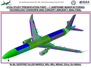
  • 1. Mr. Geoffrey Allen Wardle. MSc. MSc. ATDA Airframe Design Study 2012-2020 By Mr. GEOFFREY ALLEN WARDLE. MSc. MSc. MRAeS. CEng. Snr MAIAA. ATDA STUDY PRESENTATION PART: - 1 (AIRFRAME MANUFACTURING TECHNOLOGY OVERVIEW AND CONCEPT AIRCRAFT ANALYSIS).
  • 2. Mr. Geoffrey Allen Wardle. MSc. MSc. ATDA Airframe Design Study 2012-2020 This presentation has been created, for the sole purpose of private study and is not the work of a company or government organisation it entirely the work of the author using resources in the public domain. The final paper will be submitted for peer - review to the American Institute of Aeronautics and Astronautics, Design Engineering Technical Committee, and the RAeS Structures and Materials Group, for pre submission assessment. Readers must be aware that the work contained may not be necessarily 100% correct, and caution should be exercised if this project or the data it contains is being used for future work. If in doubt, please refer to the AIAA, Design Engineering Technical Committee and the author. All of the views and material contained within this document are the sole research of the author and are not meant to directly imply the intentions of the Boeing Company, Airbus Group, GKN Aerospace, or any contractor thereof, or any third party at this date. Although the USAF and NASA have awarded contracts for studies into stitched composite transport aircraft structures, this work is not the product of their results or any part of their body of research, and should not be considered as such. This document contains no material what so ever generated or conceived by myself or others during my employment with BAE SYSTEMS (PLC), or that is governed by ITAR restrictions. This work is solely my own creation and is based on my own academic studies and literature research and the distribution of all information contained within this document is unlimited public release and has been approved through the AIAA. This document and any part thereof cannot be reproduced by any means in any format or used for any other research project without consultation with AIAA Design Engineering Technical Committee or the author. 2 Presentation “Health” Warning. .
  • 3. Mr. Geoffrey Allen Wardle. MSc. MSc. ATDA Airframe Design Study 2012-2020 3 This is an overview covering my current private design trade studies into the incorporation of new structural technologies and manufacturing processes into a future transport airframe design, and the incorporation of mission adaptive wing (MAW) technology for per review through the AIAA This study has been undertaken after my 13 years at BAE SYSTEMS MA&I, in airframe design development as a Senior Design Engineer, and my Cranfield University MSc in Aircraft Engineering completed in 2007(part-time), and was commenced in 2012 and I aim to complete it at the end of 2020. This utilises knowledge and skills bases developed throughout my career in aerospace, academic studies and new research material I have studied, to produce a report and paper exploring the limits to which an airframe research project can be perused using a virtual tool set, and how the results can be presented for future research and manufacturing. The toolsets used are Catia V5.R20 for design / analysis / kinematics / manufacturing simulation: PATRAN / NASTRAN for analysis of composite structures: AeroDYNAMIC™ for analysis of aircraft OML / Structural Loads / performance. This work will also form the basis for a PhD study, it is the product of my own research, and has not in any part been produced or conceptualised during my employment with BAE SYSTEMS or any company which is any part thereof. About this presentation:- This presentation is Part 1 of a series of 5 presentation Parts which cover the airframe major structural component development and engine and landing gear integration, and assembly manufacturing technologies. The contents of this presentation are given in the following slide. Overview of my current research activities in aircraft design for the ATDA paper.
  • 4. Mr. Geoffrey Allen Wardle. MSc. MSc. ATDA Airframe Design Study 2012-2020  Section 1:- Overview of the ATDA airframe design development study.  Section 2:- Benefits of Z- direction reinforcement in composite laminates:  Section 3:- PRSEUS Structural element design and processing:  Section 4:- Overall loading on transport aircraft primary structures:  Section 5:- Structural design philosophies employed in the design of airframe components:  Section 6:- ATDA PRSEUS airframe concept design structural analysis and component sizing. ONLY WORK FROM REFERENCED STUDIES MAY BE REPRODUCED WITHOUT EXPRESS PERMISSION OF MYSELF, RAeS, AND AIAA. 4 Table of contents of this ATDA Study Presentation Part 1.
  • 5. Mr. Geoffrey Allen Wardle. MSc. MSc. ATDA Airframe Design Study 2012-2020 Currently I am conducting a conceptual design research into the application the Future Integrated Structure (FIS) technology PRSEUS (using NASA/TM-2009-215955 (ref 1) and NASA/CR-2011- 216880 (ref 2), as my starting point) and mission adaptive flight control surfaces, to future large transport aircraft, as detailed in charts 1 to 6, chart 7 shows the projected baseline operational profile used in loads and fuel tank sizing calculations. This is a technical report for per review through the AIAA, future PRSEUS studies and the work breakdowns are shown in charts 8,9,10. The reference baseline aircraft selected is for a CFC twin engine 250-300 seat class aircraft design of conventional configuration. Table 1 presents design data and figures 1(a)/(b) illustrate the configuration of the Baseline ATDA aircraft, and figure 2 shows the supercritical airfoil selected the ATDA aircraft. This conventional design using the current materials technology shown in figure 2, and will be compared with an improved baseline design incorporating PRSEUS (FIS) technology figures 5, 6, 7 and 8, and Mission Adaptive Wing MAW Control surfaces, figures 9 and 10, to be designed using Catia V5.R20, to determine the structural / weight / and aerodynamic benefits at the trade study level and finally more advanced aircraft design configurations will be used to determine future potential applications. The study consists of three phases:- (1) The overall airframe configuration design and parametric analysis using both classical analysis and the Jet306 / AeroDYNAMIC V2.08 analysis tool set based on my Cranfield MSc: (2) The second is major structural wing component layout of the airframe initial structure with preliminary systems integration, and using Cranfield University methods and Catia V5.R20 GSA for structural sizing. (3) The final design study for both versions of the wing reference and new build will consist of parametric analysis, initial optimisation and structural layout and analysis and constitutes a feasibility study proposal to determine the benefits, and constraints on such an application. Section 1:- Overview of the ATDA airframe design development study. 5
  • 6. Mr. Geoffrey Allen Wardle. MSc. MSc. ATDA Airframe Design Study 2012-2020 IMPERIAL DATA. METRIC DATA. Wing Span (ft / in) 231 / 3.3 Wing Span (m) 70.52 Length (ft / in) 240/88 Length (m) 75.88 Wing Area (sq ft) 4,375.49 Wing Area (sq m) 406.481 Fuselage diameter (in) 235.83 Fuselage diameter (m) 5.99 Wing sweep angle 35° Wing sweep angle 35° Fuselage Length (ft /in) 244 / 3.8 Fuselage Length 74.47 Engine number / type 2 X RR Trent XWB Engine number / type 2 X RR Trent XWB T-O thrust (lb) 83,000 T-O thrust (kN) 369.0 Max weight (lb) 590,829 Max weight (tonnes) 268.9 Max Landing (lb) 451,940 Max Landing (tonnes) 205.0 Max speed (mph) 391 Max speed (km/h) 630 Mach No 0.89 Mach No 0.89 Range at OWE (miles) 9,631 Range at OWE (km) 15,500 Cruise Altitude (ft) 45,000 Cruise Altitude (m) 13,716 6 Table 1(a):- Initial Configuration Aircraft Data for the baseline ATDA study.
  • 7. Mr. Geoffrey Allen Wardle. MSc. MSc. ATDA Airframe Design Study 2012-2020 Figure 1(a):- Overall configuration and dimensions of the ATDA baseline aircraft. 7 70.52m (231ft 3.3in) Code F 18.34m (60ft 7in) 11.51m (37ft 1.6in) 30.58m (100ft 3.8in) O/A 75.87m (248ft 1.3in) Code E 74.47m (244ft 3.8in) 34.45m (113ft 2.4in) O/A 75.27m (246ft 10.7in) Fuselage sized for twin aisle 9 abreast 2 LD-3 containers 5.99m (235.85in) Section on ‘A’ ‘A’ ‘A’ 17.85m (58ft 4.6in) 11.92m (39.136ft) 7.771m 14.154m 17.248m For all analysis measurements see Section 6
  • 8. Mr. Geoffrey Allen Wardle. MSc. MSc. ATDA Airframe Design Study 2012-2020 Figure 1(b):- ATDA Configuration C of G, Tip back, and Overturn angles. 8 11.51m (37ft 1.6in) 75.87m (248ft 1.3in) Code E 74.47m (244ft 3.8in) 34.45m (113ft 2.4in) 17.85m (58ft 4.6in) Aft C of G 36.787m C of G 36.089m Fwd C of G 36.089m Fwd C of G 36.089m Aft C of G 36.787m 43° 57° 10° NLG MLG 75° From analysis of the Catia Concept model Tip back angle = 10°: Overturn angle = 75°
  • 9. Mr. Geoffrey Allen Wardle. MSc. MSc. ATDA Airframe Design Study 2012-2020 9 Figure 2:- Aerofoil profile selection based on near laminar flow section. Figure 2a/b:- Flow fields around 2(a) conventional aerofoil 2(b) supercritical aerofoil. Figure 2(a) Figure 2(b) Figure 2(c):- Sketches of root NASA SC(2) 0414 and tip NASA SC(2) 0410 aerofoil profiles.
  • 10. Mr. Geoffrey Allen Wardle. MSc. MSc. ATDA Airframe Design Study 2012-2020 10 AL/Li Alloy CFRP MONOLITIC CFRP SANDWICH TITANIUM QUARTZ GLASS By weight percentage. Composites 50% Titanium 15% Steel 10% Other 5% AIRBUS A350-900 XWB Airframe. BOEING 787-8 Airframe. Figure 2(d):- Materials utilization on current generation commercial airframes.
  • 11. Mr. Geoffrey Allen Wardle. MSc. MSc. ATDA Airframe Design Study 2012-2020 My current research activities in aircraft design for the ATDA project. Aircraft design studies are a detailed and iterative procedure involving a variety of theoretical and empirical equations and complex parametric studies. Although aircraft specifications are built around the basic requirements of payload, range and performance, the design process also involves meeting overall criteria in terms of, for example, take-off weights, airport constraints, maintainability and operating cost. The main issues come from the interdependency of all of the design variables involved, in particular the dependency relationship between wing area, engine thrust, and take-off weight which are complex and often require an initial study of existing aircraft designs to get a first impression of the practicality of the proposed design, this is the process adopted by myself in designing the reference wing based upon the most recent fielded technology. An aircraft design trade study can be considered to two phases:- the initial „first approximation‟ methodology: followed by „parametric analysis‟ stages, although in practice the process is more iterative than purely sequential. Table 2 shows the basic steps to generate configuration data for AeroDYNAMIC MDO toolset, with some general rules of thumb, based on concept design experience. Chart 5 illustrates the development stages, for evaluation the Baseline, PRSEUS airframes and future concepts employing this technology. The AeroDYNAMIC™ toolset was used to produce parametric study plots showing the bounds of the design which fitted the chosen design criteria and are incorporated in the full study paper. 11
  • 12. Mr. Geoffrey Allen Wardle. MSc. MSc. ATDA Airframe Design Study 2012-2020 Requirements Cascade.  Starting with the customer needs, Top Level Aircraft Requirements (TLAR) are formulated e.g.:- Number of passengers / seats: Weight target: Cargo / baggage payload: Range: etc.  These requirements were broken down into requirements for the Major Airframe Components of the aircraft Top Level Structural Requirements Studies (TLSRS) e.g. for:- Fuselage: Wing: Empennage: Systems.  These were further broken down to Section Level Requirements (SLR) for each structural component e.g. for:- Skins: Stringers: Floor Beams.  All of these are governed by Design Principles and Standards for which for commercial aircraft I have researched the AIAA ARC :- (Reference Structural Design Principles and Systems Installation Design Principles). For Airbus there are the RSDP which are Design Principles for airframe structural design, and SIDP which are Design Principles for designing and integrating aircraft systems. 12 My requirements research breakdown for the ATDA aircraft design project.
  • 13. Mr. Geoffrey Allen Wardle. MSc. MSc. ATDA Airframe Design Study 2012-2020 13 Table 1(b):- ATDA Project Top Level Aircraft Requirements for this design project. Key Requirements Current Best Standard Target Low Cost Current Unit Cost Gap 20% reduction High Rate Manufacture Production rate 32 pa 50% increase Rapid ramp up and Cut Over 30 pa over 2 years 10 fold improvement Significant Performance Improvements A350 Standard 268.9 tonne 242.01 tonne (10%>) Aerodynamics A350-1000 Standard 3% drag reduction Cruise altitude A350-1000 Standard 45,000ft / 13,716m Range A350-1000 Standard 9,631m / 15,500km Capacity two class seating A350 -1000 Standard 350 in 9 abreast Capacity three class seating A350 -1000 Standard 315in 9 abreast Cargo Capacity A350 -1000 Standard 8pallets +18LD3‟s Cabin Altitude Pressure A350-1000 Standard 6000ft / 1,829m (20% humidity) Minimise NRC A350-1000 Standard 50% reduction DMC improvement 64$/FH 30% reduction
  • 14. Mr. Geoffrey Allen Wardle. MSc. MSc. ATDA Airframe Design Study 2012-2020 14 Chart 1(a):- ATDA Project House of Quality Aircraft Requirements analysis. Design Features Light High RM Low DMC Advanced Lower High P High C Customer Needs Customer Needs Weight Auto Ass Low OC Structure Drag/SFC Capacity Capacity Priorities Rank Low Cost 20% reduction on A350 Family 9 3 6 0 2 2 0 0.080 1 Long Range 15,500km (9,631nm) 0 8 2 9 9 3 9 0.080 2 DMC 30% reduction on A350 /B787 5 0 3 6 3 3 2 0.060 3 High Rate Manufacture 48 aircraft /year 6 0 0 6 4 9 9 0.080 4 Aerodynamics 3% drag reduction 6 0 9 2 9 9 9 0.065 5 Damage tolerant PRSEUS structure 9 0 8 4 0 8 7 0.050 6 Economic Cruise Alititude 13,716m 8 1 5 5 5 0 8 0.080 7 Structural limit loads 50% fuel +2g to -2g 5 0 8 4 4 5 6 0.050 8 Maximum speed Mach 0.89 2 0 9 9 8 6 8 0.050 9 Weight 242.01 tonne 3 6 5 0 2 0 6 0.040 10 Capacity two class 9 abrest 350 4 0 0 4 5 5 2 0.063 11 Capacity three class 9 abrest 315 7 7 5 8 8 6 8 0.062 12 Cargo Capacity 8 pallets + 18LD3's 7 8 5 9 9 5 8 0.080 13 Cabin altitude pressure 1,829m 20% humidity 8 0 8 6 3 2 5 0.040 14 Rapid ramp up and Cut Over 8 0 8 7 6 0 5 0.030 15 Minimised NRC 50% reduction 8 0 8 7 5 0 5 0.030 16 Compatible with all airports A350 /B787 8 0 8 7 5 2 5 0.030 17 Single source engine supplier 369kN TO thrust 6 0 9 8 4 2 2 0.030 18 Design Feature Priorities 5.916 2.274 5.275 5.518 5.296 4.122 6.047 1.000 Checksum Target values 242 tonne 48 a/pa 30%> 2020 3%> 350 8+18LD3 Positive Synergy Interference negative Strong Positive
  • 15. Mr. Geoffrey Allen Wardle. MSc. MSc. ATDA Airframe Design Study 2012-2020 The fundamental reasons for this research is to reduce the structural weight of the airframe and make it easer to produce through PRSEUS technology. The former is intended to reduce the amount of CO2 emitted from kerosene – burning aircraft engines which is solely dependent on the amount of fuel consumed (discussed below), and the latter will reduce costs both of acquisition and ownership through life maintenance (discussed in section 2). The variables influencing fuel consumption can easily be examined using the Breguet range equation. One form of the range equation for the special case of constant lift coefficient – i.e. at constant cruise / climb – reads:- WF = WTO * 1 – exp R equation (1.0) X With WTO representing aircraft take - off weight, R the mission range; X = L / D * V = L/D *ᶇ * H equation (1.1) TSFC *g g V = the cruise speed; TSFC = the thrust specific fuel consumption; ᶇ = the overall engine efficiency; H = the cabrific value of the fuel. 15 My requirements research breakdown for the ATDA aircraft design project.
  • 16. Mr. Geoffrey Allen Wardle. MSc. MSc. ATDA Airframe Design Study 2012-2020 Now equation 1.0 can be rewritten to give fuel consumption in kg per kg payload as:- WF 1 + WE * exp R*g πeb² -1 equation (1.3) Wp Wp CL ᶇth ᶇprop H Where:- CDo = the zero-lift drag; S = the wing area; e = the Oswald factor; B = the wing span; CL = the aircrafts lift coefficient; ᶇth = the engines thermal efficiency; ᶇprop = the engines propulsive efficiency. Minimising fuel weight, with respect to CO2 emission for a given payload and range can be obtained by:-  Aerodynamics:- Maximise CL, e, and b: Minimise CDo and S;  Structure:- Minimise WE / Wp ( Weight empty / Weight payload);  Engine:- Maximise ᶇth and ᶇprop ;  Fuel:- Maximise H The body of this work is to modify the structural above listed parameter however others impact this. 16 My requirements research breakdown for the ATDA aircraft design project. = S C²L CDo +
  • 17. Mr. Geoffrey Allen Wardle. MSc. MSc. ATDA Airframe Design Study 2012-2020 17 Chart 1(b):- ATDA Project study structure task flow. Task 1:- Identify Future Scenario. Identify Advanced Structural and Manufacturing Technology Identify Advanced Vehicle Structural Concepts Analysis and Structural Sizing of Baseline aircraft configuration using Advanced structural technology.  Weight;  Performance;  Fuel Burn;  Field Length;  Emissions. Explore advanced configurations using Advanced structural technology. Task 2:- Develop Advanced Airframe:- Task 3:- Assess Airframe Technology Risk & Generate Technology Roadmap to de-risk:- Concept & Technology Risk Analysis Develop Technology Risk reduction Roadmap Task 4:- Reporting:- ATDA Airframe Report:-  Future Scenario Definition:  Advanced Vehicle Structural Concept;  Enabling Technologies and Roadmap. Establish Missions and Reference Configuration
  • 18. Mr. Geoffrey Allen Wardle. MSc. MSc. ATDA Airframe Design Study 2012-2020 18 Table 2:- Example of the „first approximation‟ methodology used in the ATDA study. Estimated parameter. Basic relationship. Rule of thumb. (1) Estimate wing loading W/S. W/S = 0.5 pV² C˪ (in the „approach‟ condition). Approach speed lies between 1.45 and 1.62 Vstall. Approach C˪ lies between C˪max /2.04 and C˪max /2.72 (2) Check C˪ in cruise. C˪ = 0.98(W/S) /q Where q = 0.5 pV² . C˪ generally lies between 0.44 and 0.5 (3) Check gust response at cruise speed. Gust response parameter α1wb .AR / (W/S) α1wb is the wing body lift curve slope obtained from data sheets. (4) Estimate size. Must comply with take-off and climb performance. The aircraft type considered i.e. long range transport have engines sized for top of the climb requirements. (5) Estimate take-off wing loading and T/W ratio as a function of C˪V2 s =kM²g²/(SwT. C˪V2 ) 1.7< C˪max < 2.2 and 1.18< C˪V2 <1.53 (6) Check the capability to climb (gust control) at initial cruise altitude. 17< L/D < 21 in the cruise for most civil airliners. (7) Estimate take-off mass. MTO = ME + MPAL + Mf 0.46< OEM / MTOM <0.57
  • 19. Mr. Geoffrey Allen Wardle. MSc. MSc. ATDA Airframe Design Study 2012-2020 19 Chart 2:- My current research activity for aircraft design trade studies ATDA project. The development and application of advanced structural concepts, and mission adaptive control surfaces to commercial aircraft. Estimated at:- 6,240hrs (15 hour weeks over 8 years) Workbook 1:- Composite airframe design and manufacture incorporating Catia V5.R20. (exercises vertical tail fighter a/c design / commercial aircraft vertical tail design) COMPLETED. Workbook 2:- FEA using Catia V5.R20. (exercises airframe structural component design and analysis) COMPLETED. Workbook 3:- Control surface kinematics Catia V5.R20. (exercises airframe flap deployment analysis) COMPLETED. Major structural layout:- Based on Cranfield MSc Aircraft Engineering modules using Catia V5.R20 as tool set. Defining airframe study concept:- MSc Aircraft Engineering modules using Catia V5.R20 as tool set and AeroDYNAMIC V3 MSc / concept engineering skills sets. Major structural loads analysis and component sizing:- Based on Cranfield MSc Aircraft Engineering modules using Catia V5.R20 as tool set.
  • 20. Mr. Geoffrey Allen Wardle. MSc. MSc. ATDA Airframe Design Study 2012-2020 20 DETERMINE AIRFRAME CONFIGURATION. DEVELOP BASELINE STRUCTURAL LAYOUT Wing size, sub structure layout, control surface layout, interfaces and LG / fuel tankage integration. Fuselage diameter, internal structural layout plus cutouts, and structural interfaces with the wing, empennage and LG. Empennage size, structural internal layout, control surface layout and sizing, interfaces with surfaces and fuselage. DETERMINE STRUCTURAL LOADING AND LOAD PATHS Structural sizing of all major airframe components. Detailed structural analysis of selected airframe components. Chart 3:- Activity dependency for the design trade studies of the ATDA airframe.
  • 21. Mr. Geoffrey Allen Wardle. MSc. MSc. ATDA Airframe Design Study 2012-2020 21 Chart 4:- Phases of the ATDA airframe PRSEUS design trade study program. Work book 1:- Composite airframe design Work book 2:- GSA airframe design Phase 1:- Baseline composite / metallic wing box, and wing / fuselage and empennage layout design structural component sizing. Baseline composite and metallic wing / fuselage / empennage design structural / weight analysis. Workbook 3:- Control surface kinematic design analysis and sizing. Phase 2:- Advanced concept composite PRSEUS wing / fuselage and empennage layout design structural component sizing. Phase 1:- Baseline control surface design, structural sizing and operational analysis. Advanced ATDA concept composite PRSEUS Airframe design Wing: Fuselage: Empennage conduct structural / weight analysis. Phase 3:- ATDA concept full composite PRSEUS Airframe layout, Landing gear, and MAW control surface integration, design structural component sizing and weight analysis. Phase 2:- MAW control surface design trades, structural sizing, weight and operational analysis.
  • 22. Mr. Geoffrey Allen Wardle. MSc. MSc. ATDA Airframe Design Study 2012-2020 STAGE 1:-DEVELOPMET OF BASELINE AIRFRAME. Generate concept iterations for parametric analysis using AeroDYNAMIC™ to give sizing of major airframe components against mission requirements, first pass airframe structural loads drop. Use initial loadings for preliminary sizing of airframe sub-structure, integrating between major airframe component interfaces and installations (power plants, landing gear, fuel tankage) as a Composite / metallic airframe build to Airbus / Boeing design standards meeting FAA / CAA design regulations. Produce a preliminary airframe design using Catia V5.R20 and Patran / Nastran toolset, to be using current manufacturing technology which forms the baseline for the PRSEUS trade study. STAGE 2:- EVOLUTION OF BASELINE TO PRSEUS STRUCTURE. Using the baseline airframe for a twin engined twin aisle long range transport develop a PRSEUS stitched airframe alternative retaining the same sub structure layout and OML, to be produced using RTM and RIM techniques. Analyse the resulting airframe structure and compare with the conventional baseline airframe in terms of weight, complexity, ease of imparting design intent to manufacturing. Conduct airframe assembly studies, to determine possible automated assembly of major airframe components. Conduct integration studies of proposed mission adaptive flight control systems for the wing and empennage, factoring these into complexity and performance trades. STAGE 3:-FUTURE CONCEPTS. Apply the results and experience gained in stages 1 and 2 to the design and development of advanced configuration airframes to maximise the benefits of PRSEUS stitched composite structural technology, advanced manufacturing and automated assembly technology, and mission adaptive control surfaces. These airframe concepts are to be in both single aisle medium range, and twin aisle long range transports. Also to be explored is the application of thermoplastic resin matrix composites and processing technologies. 22 Chart 5:- Development Stages of the PRSEUS airframe design for the ATDA program.
  • 23. Mr. Geoffrey Allen Wardle. MSc. MSc. ATDA Airframe Design Study 2012-2020 23 Chart 6:- Design Trade Study Project Milestones for the ATDA Project.
  • 24. Mr. Geoffrey Allen Wardle. MSc. MSc. ATDA Airframe Design Study 2012-2020 24 Chart 7(a):- Design Trade Study Operational Profile for the ATDA aircraft sizing. Based on Reference 12 profiles. 15,500km (9,631m) 370km (230m) 45,000 ft 13,716m Nominal Performance: Standard Day: Jet A Kerosene Fuel density:- 820 kg/m³ Baseline Mission Based on Reference 12 profiles.
  • 25. Mr. Geoffrey Allen Wardle. MSc. MSc. ATDA Airframe Design Study 2012-2020 25 Chart 7(b):- Desired Operational Profile for the ATDA aircraft concept design. 45,000 ft 13,716m 15,500km (9,631m) 370km (230m) Based on Reference 12 profiles. Nominal Performance: Standard Day: Jet A Kerosene Fuel density:- 820 kg/m³ Revised Mission Cruise at LRC Mach Changes:-  Reduced taxi times:  Optimised climb:  Cruise climb:  Loiter eliminated:  Reduction in flight fuel allowance  Reduction in hold time.
  • 26. Mr. Geoffrey Allen Wardle. MSc. MSc. ATDA Airframe Design Study 2012-2020 26 Chart 7(c):- Landing and take off obstacle clearance for the ATDA aircraft concept design. 15.24m 10.67m FLARE DE-ROTATE ROTATE TAKE-OFF APROACH Ԏ= -3°
  • 27. Mr. Geoffrey Allen Wardle. MSc. MSc. ATDA Airframe Design Study 2012-2020 27 Composite Wings and Empennage applied PRSEUS stitched composite technology. All electric control system with MAW technology and advanced EHA actuation system. Hybrid Laminar Flow Control on wing upper surface. Composite Fuselage applied PRSEUS stitched composite stringers. Natural Laminar Flow on nacelles. Advanced Engines. Variable Trailing Edge Camber. Wing aspect ratio >10. Riblets on fuselage. Hybrid Laminar Flow Control on Vertical and Horizontal tails . SOFC/GT Hybrid APU. Positive control winglets. HT Thermoplastic composite engine pylons. Thermoplastic composite fuselage frames. Thermoplastic composite Belly Fairing. Chart 8:- Advanced Technology Demonstrator Aircraft “Tube and Wing” 2030.
  • 28. Mr. Geoffrey Allen Wardle. MSc. MSc. ATDA Airframe Design Study 2012-2020 Wing Carry Trough Box Structure defined and sized ( section 7 wing report). PRSEUS stitched composite technology empennage 2016-2020. PRSEUS stitched composite technology wing 2013-2018. Automated Assembly of wing structure 2016-2020. Thermoplastic composite fuselage frames 2017-2018. Positive control winglets 2016-2020. Composite Fuselage applied PRSEUS stitched composite stringers 2017-2018. Thermoplastic composite Belly Fairing 2017-2020. H Temp Thermoplastic composite engine pylons proposed 2016-2018. Wing Torsion Box Structure defined and sized (section 7 wing report). 28 Chart 9:- My Advanced Technology Demonstrator Aircraft Project Work Breakdown.
  • 29. Mr. Geoffrey Allen Wardle. MSc. MSc. ATDA Airframe Design Study 2012-2020 29 Fwd CFC Barrel Section (B787 example). Aft CFC Barrel Section (A350 example). Section 15 CFC Keel Panel (A350 example). Section 13/14 Crown panel:- Area = 68.051m²: Length = 12.792m Section 15 Crown panel:- Area = 110.074m²: Length = 20.645m Section 16/18 Crown panel:- Area = 74.569m²: Length = 14.391m Port Section 13/14 Side panel:- Area = 39.176m²: Length = 12.792m Port Section 15 Side panel:- Area = 63.635m²: Length = 20.645m Port Section 16/18 Side panel:- Area = 47.865m²: Length = 14.391m Section 13/14 Keel panel:- Area = 87.734m²: Length = 12.792m Section 15 Keel panel:- Area = 92.423m²: Length = 20.645m Section 16/18 Keel panel:- Area = 94.923m²: Length = 14.391m Analysis will be of Section 15 Panels initially. (*Note Port and Stbd side panel dimensions are identical). Chart 10(a):- ATDA Fuselage design build philosophy selected and panel sizing.
  • 30. Mr. Geoffrey Allen Wardle. MSc. MSc. ATDA Airframe Design Study 2012-2020 30 Chart 10(b):- ATDA Fuselage cabin window line cargo bay sizing and spacing. Window C/L 1,750mm above cabin floor top surface OML. Clearance = 5cm Clearance = 7.62cm 1.62m 1.87m LD3 Container. VIEW LOOKING AFT. Planned Passenger capacity 320:- 48 in Business class 6 abreast (8 rows) and 272 in Economy class 9 abreast (30 rows). Planned cargo capacity 36 standard LD3 containers, or 11 Pallets. The proposed fuselage PRSEUS and thermoplastic application design and structural development will use Airbus composite fuselage structural design philosophy with a Boeing style CFC barrel cabin / nose section, and a CFC barrel tail section. Composite Fuselage skins with PRSEUS stitched composite stringers. Monolithic back to back C- section Thermoplastic resin composite fuselage frames.
  • 31. Mr. Geoffrey Allen Wardle. MSc. MSc. ATDA Airframe Design Study 2012-2020 Conventional laminated two-dimensional composites are not suitable for applications where trough thickness stresses may exceed the (low) tensile strength of the matrix (or matrix / fibre bond) and in addition, to provide residual strength after anticipated impact events, two–dimensional laminates must therefore be made thicker than required for meeting strength requirements. The resulting penalties of increased structural weight and cost provide impetus for the development of more damage-resistant and tolerant composite materials and structures. Considerable improvements in damage resistance can be made using tougher thermoset or thermoplastic matrices together with optimized fibre / matrix bond strength. However, this approach can involve significant costs, and the improvement that can be realized are limited. There are also limits to the acceptable fibre / matrix bond strength because high bond strength can lead to increased notch-sensitivity. An alternative and potentially more efficient means of increasing damage resistance and through- thickness strength is to develop a fibre architecture in which a proportion of fibers in the composite are orientated in the z-direction. This fibre architecture can be obtained, for example, by three- dimensional weaving or three-dimensional breading. However a much simpler approach is to apply reinforcement to a conventional two-dimensional fibre configuration by stitching: although, this dose not provide all of the benefits of a full three- dimensional architecture. In all of these approaches, a three dimensional preform produced first and converted into a composite by either RTM / VARTM, or CAPRI (see later in this presentation). Even without the benefits of three-dimensional reinforcement, the preform approach has the important advantage that it is a comparatively low-cost method of manufacturing composite components compared with conventional laminating procedures based on pre-preg. 31 Section 2:- The structural benefits of 3-D stitched and pinned composites.
  • 32. Mr. Geoffrey Allen Wardle. MSc. MSc. ATDA Airframe Design Study 2012-2020 32 The structural benefits of 3-D stitched and pinned composites over conventional laminates. (a) Lock stitch (b) Modified Lock stich (c) Chain stitch Needle Thread Bobbin Thread Needle Thread Bobbin Thread Figure 3:-Schematic diagram of three commonly used stitches for 3-D reinforcement. Indeed, preforms for resin transfer molding (RTM) and other liquid molding techniques are often produced from a two dimensional fibre configuration by stitching or knitting. Stitching:- This is best applied using an industrial-grade sewing machine where two separate yarns are used. For stitching composites, the yarns are generally aramid (Kevlar), although other yarns such as glass, carbon, and nylon have also been used. A needle is used to perforate a pre- preg layup or fabric preform, enabling the insertion of a high–tensile-strength yarn in the thickness direction. In the case of the PRSEUS process a Vectran thread impregnated with epoxy resin is used. The yarn, normally referred to as the needle yarn, is inserted from the top of the layup / preform, which is held in place using a presser foot. When the yarn reaches the bottom of the layup / preform it is caught by another yarn, called the bobbin yarn, before it re-enters the layup / preform as the needle is withdrawn from the layup / preform, thus forming a full stich. The layup / preform, is then advanced a set distance between the presser foot and a roller mechanism before the needle is used to apply the next stitch. This process is repeated to form a row of stitches. Figure 3 shows the various types of stitches commonly used to create z-direction reinforcement.
  • 33. Mr. Geoffrey Allen Wardle. MSc. MSc. ATDA Airframe Design Study 2012-2020 Among the three stitches shown in figure 3, the modified lock stitch in which the crossover knot between the bobbin and needle threads is positioned at either laminate surface, to minimize in- plane fibre distortion is considered the best, and is the preferred method. Apart from improving z- direction properties, stitching serves as an effective means of assembling preforms of dry two- dimensional tape or cloth, for example, attaching stringers to skin preforms, that can then be consolidated using liquid molding. Mechanical Properties Improvements: - (1) Out-of-Plane properties are significantly improved by stitching, increasing the interlaminar delamination resistance for fibre reinforced plastic laminates under mode I (tensile loading KIC) and to a lesser extent mode II (shear loading KIIC) loadings. In order achieve this, the stiches need to remain intact for a short distance behind the crack front and restrict any effort to extend the delamination crack. With such enhanced fracture toughness stitched laminates have better resistance to delamination cracking under low energy, high energy and ballistic impacts as well as under dynamic loading by explosive blast effects. Stitched laminates also possess higher post-impact residual mechanical properties than non-stitched laminates. Studies (ref 6) have shown that the effectiveness of stitching for improving residual strength is dependent on factors such as the stitch density, stitch type, and stitch thread. Although the best improvement in compression post impact strength has been found in relatively thick laminates, and though similar improvements in residual strength have been observed in toughened matrix laminates the latter is two to three times more expensive than stitching. Stitching also improves shear lap joint strength under both static and cyclic loading, largely due to reducing the peel stresses. Stitching can delay the initiation of disbonds and provide load transfer even after bond line failure. Stitching is also effective in suppressing delamination due to free edge effects. 33 The structural benefits of 3-D stitched and pinned composites over conventional laminates.
  • 34. Mr. Geoffrey Allen Wardle. MSc. MSc. ATDA Airframe Design Study 2012-2020 (2) In-Plane properties of a two dimensional composite laminate can also be affected by stitching, due the introduction of defects in the final laminate during needle insertion or as a result of presence of the stitch yarn in the laminate. These defects may occur in various forms including broken fibres, resin-rich regions, and fine scale resin cracking. Fibre misalignment however appears to have the greatest detrimental effect on mechanical properties, particularly under in plane tensile and compressive loading. In order to keep defects resulting from stitching to a minimum, careful selection and control of the stitching parameters (including:- yarn diameter: yarn tension: yarn material: stitch density: etc.), are essential. Analysis of the effects of stitching on in-plane material properties of two dimensional composite laminates in general have been somewhat inconclusive (ref 6), with studies showing that stiffness and strength of the composites under tensile and compressive loadings can be either degraded, unchanged, or improved with stitching, depending on the type of composite, the stitching parameter, and the loading condition. The improvements in tensile and compressive stiffness have been attributed to the increase in fibre / volume fraction that results from a compaction of the in- plane fibres by stitching. The enhancement in compressive strength is attributed to the suppression of delamination's. The stiffness in tension and compression is mainly degraded when in-plane fibres are misaligned by the presence of the stitching yarn in their path. Premature compressive failure can result from the stitching being too taut, which in turn can cause excessive crimping of the in- plane fibres. Conversely, insufficient tension on the stitching yarn can cause the stitches to buckle under consolidation pressures and render them ineffective as a reinforcement in the thickness direction, which was the original intention. Tensile strength however is normally degraded due to fibre fractures arising from damage inflicted by the stitching needle. 34 The structural benefits of 3-D stitched and pinned composites over conventional laminates.
  • 35. Mr. Geoffrey Allen Wardle. MSc. MSc. ATDA Airframe Design Study 2012-2020 Enhancements of tensile strength, which has been observed, is attributed to an increase in fibre / volume fraction resulting from compaction of the in-plane fibres by the stitching. The in-plane fatigue performance is also considered to be degraded due to the same failure mechanisms responsible for degradation of their corresponding static properties. Finally, it appears that the flexural and interlaminar shear strengths of two-dimensional laminates may also be degraded, unchanged, or improved with stitching. In general, the conflicting effects of stitching, in increasing fibre content and suppressing delamination, on one hand, and introducing misalignment and damage to in-plane fibres on the other, are possibly responsible for the reported behaviors. Z-Pinning:- This is a simple method of applying three-dimensional reinforcement with several benefits over stitching. However, unlike stitching, z-pinning cannot be used to make preforms and therefore is included here for completeness. In the z-pinning process, thin rods are inserted at right angles into a two-dimensional carbon / epoxy composite laminate, either before or during consolidation. The z-rods can be metallic, usually titanium, or composite, usually carbon / epoxy, and these are typically between 0.25mm (0.0098 inch) and 0.5mm (0.0197 inch) in diameter. These rods are held with the required pattern and density in a collapsible foam block that provides lateral support, this prevents the rods from buckling during insertion and allows a large number of rods to be inserted in one operation. The z-rods are typically driven into the two-dimensional composite by one of two methods as shown in figure 4. The first method (figure 4(a)) involves placing the z-rod laden foam on top of an uncured pre-preg and autoclave curing. During the cure, the combination of heat and pressure compacts the collapsible foam layer, driving the rods orthogonally into the composite. 35 The structural benefits of 3-D stitched and pinned composites over conventional laminates.
  • 36. Mr. Geoffrey Allen Wardle. MSc. MSc. ATDA Airframe Design Study 2012-2020 When curing is completed, the residual foam preform is then removed and discarded, and the z- rods sitting proud of the surface of the cured laminate are sheared away using a sharp knife. The second method uses a purpose built ultrasonic insertion transducer to drive the z-rods into the two-dimensional composite and is shown schematically in figure 4(b). This is a two stage process, and during the first stage the preform is only partially compacted using the ultrasonic insertion transducer, and thus the z-rods are not fully inserted. The residual foam is then removed, and a second insertion stage is carried out with the ultrasonic insertion transducer making a second pass to complete the insertion of the z-rods. If the z-rods are not flush with the part surface, the excess is sheared away. In principle, the part to be z-pinned could take on any shape provided there is an appropriate ultrasonic insertion transducer. Research indicates that the ultrasonic insertion technique can be used to insert metallic pins into cured composites for the repair of delamination's, although a considerable amount of additional damage to the parent material results and further trade studies are required to determine its true viability. Of the two z-pinning insertion methods the vacuum bag method is more suitable when a large or relatively flat and unobstructed area is to be z-pinned. The ultrasonic method is more suitable for z- pinning localized or difficult to access areas by configuring and shaping an appropriate ultrasonic insertion transducer. Mechanical Properties Improvements: - (1) Out-of-Plane properties indicate a significant improvement in both mode I (tensile loading KIC) and mode II (shear loading KIIC) fracture toughness, achieved through z-pinning based on published data, which would translate into superior damage resistance and tolerance, as well as improved skin stiffener pull out properties. 36 The structural benefits of 3-D stitched and pinned composites over conventional laminates.
  • 37. Mr. Geoffrey Allen Wardle. MSc. MSc. ATDA Airframe Design Study 2012-2020 37 Figure 4 (a)/(b):- Z-Pinning process an alternative to stitching. TOOL Vacuum Bag Prepreg Composite Z-Fibre Preform TOOL PRESSURE TOOL Remove & Discard Foam Cure Z-Pinned Composite Stage 1:- Place Z-Fibre Preform on top of Prepreg and then enclose in vacuum bag. Stage 2:- Standard cycle or debulk cycle, heat and pressure compact preform foam, forcing the Z-pins into the Prepreg composite. Stage 3:- Remove compacted preform foam and discard Finish with cured Z- pinned composite. Figure 4(a). Figure 4(b). Remove Used Preform Uncured Composite Z-Fiber Preform Ultrasonic Insertion Transducer (a) Primary insertion stage and residual preform removal. (b) Secondary insertion stage.
  • 38. Mr. Geoffrey Allen Wardle. MSc. MSc. ATDA Airframe Design Study 2012-2020 (2) In-Plane properties current research (ref 6) indicates that the improvements in out-of-plane properties are achievable without much if any, sacrifice of in-plane properties, although other work indicates that the z-pins can introduce excessive waviness to the in-plane fibres, resulting in compressive properties being severely degraded. As with the stitched 3-d reinforcement, the degree to which the in-plane properties are detrimentally affected, and the out-of-plane properties are improved, depends on the pinning parameters, such as pinning density and pattern configuration. Z-direction reinforcement:- Research into z-direction reinforcement of traditional 2-D laminate mechanical properties has been particularly extensive, and the impetus is derived from the potential of both stitching and z-pinning to address the poor out-of-plane properties of conventional 2-D fibre reinforced composites, in a cost-effective method. The amount of z-direction reinforcement needed to provide a substantial amount of out-of-plane property improvement is small and values of 5% are typical. The improvements in fracture toughness resulting from these processes mean that higher design allowables could be used in the design of composite structures. Stitched and z-pinned components could reduce the layup complexity, and weight for structures subjected to: - the risk of impact damage (e.g. due to dropped tools), high peel stresses (e.g. in joints and at hard points), and cut-outs (e.g. edges and holes) that are difficult to avoid in aircraft design. Stitching and z- pinning also provide the opportunity for parts integration to be incorporated into the production of composite components, thus improving the ease of handling in automated assembly processes, and the overall cost-effectiveness of the manufacturing process. When used in conjunction RIM / RTM stitching provides pre-compaction of the preform that enables reduces the mold clamping pressures while ensuring a high fibre / volume fraction in the finished product. 38 The structural benefits of 3-D stitched and pinned composites over conventional laminates.
  • 39. Mr. Geoffrey Allen Wardle. MSc. MSc. ATDA Airframe Design Study 2012-2020 39 The fundamentals of PRSEUS structural concept as shown in figure 5 is to arrest damage growth and enable a full fail-safe design philosophy to be adopted for major composite airframe components. This study proposes to examine the feasibility of using this structural concept to reduce the weight of the: - wing, fuselage and empennage large transport aircraft. As conceived in NASA/CR-2011-216880, the PRSEUS was applied to bi-directionally stiffened panel design, to resist loading where the span wise wing bending are carried by the frame members (like skin / stiffeners on a conventional transport wing), and the longitudinal (fuselage bending loads in a HWB aircraft), and pressure loads being carried by the stringers, I feel this concept could be used to take the bending, torque, and fuel pressure loads in a conventional wing, and also applied to tube fuselages and empennage of conventional layout. This view is supported by a NASA sponsored Boeing stitched / RFI wing demonstrator program of 1997, which produced 28m (92ft) structure 25% lighter and 20% cheaper than an equivalent aluminium structure. The highly integrated nature of PRSEUS is evidenced by figures 5(a)/(b), and 8 and 9 which shows ATDA specific structural assemblies of dry warp-knit fabric core, pultruded rods, materials, which are then stitched together to create the optimum structural geometry. Load path continuity at the stringer – frame intersection is maintained in both directions. The 0º fiber dominated pultruded rod increases local strength / stability of the stringer section while simultaneously shifting the neutral axis away from the skin to enhance overall panel bending capability. Stringer elements are placed directly on the IML (Inner Mold Line), skin surface and are designed to take advantage of carbon fiber tailoring by placing bending and shear – conductive layups where they are most effective. The stitching is used to suppress out-of-plane failure modes, which enables a higher degree of tailoring than would be possible using conventional laminated materials. PRSEUS Structural element design derived from NASA/CR-2011-216880.
  • 40. Mr. Geoffrey Allen Wardle. MSc. MSc. ATDA Airframe Design Study 2012-2020 40 Figure 5(a):- Fundamentals of the PRSEUS airframe technology explored. 2 Rows of stitching 2 Rows of stitching Pultruded Rod Over wrap knit fabric PRSEUS:- Pultruded Rod Stitched Efficient Unitised Structure (Stringer). Stitched Stub Rib Stitched Stub Rib Tensile Load Tensile Load PRSEUS Stitched Stringer HT Lower Cover Skin Induced crack defect Damage growth A B C D Failure methodology A = Damage growth initiated : B = Damage arrested by PRSEUS Stringer flange: B - C = Fibre split damage growth: C = Damage arrested by PRSEUS Stub Rib flange: D = Skin failure at DLL. 0ºSkin Fibre Direction 0ºStub Rib Fibre Direction
  • 41. Mr. Geoffrey Allen Wardle. MSc. MSc. ATDA Airframe Design Study 2012-2020 41 Figure 5(b):- Examples of the PRSEUS airframe technology explored. Load Displacement  Arrested damage enables fail- safe design philosophy:  Furthermore PRSEUS meets the requirements of FAR Part 25:- 25.571 Damage - tolerance and fatigue evaluation of structure in that:- PRSEUS identifies the principle structural elements and multi-bay damage scenarios, and validates damage arrestment and residual strength by test and analysis.
  • 42. Mr. Geoffrey Allen Wardle. MSc. MSc. ATDA Airframe Design Study 2012-2020 The currently PRSEUS for HWB airframe design with its continuous load paths higher notch design properties, and larger allowable damage levels represents a substantially improved level of performance beyond that which would be possible using unstitched materials and designs. In addition to the enhanced structural performance, the PRSEUS fabrication approach is ideally suited to compound curvatures as may be found in advanced transport concepts. The self supporting stitched preform assembly feature that can be fabricated without exacting tolerances and then accurately net molded in a single oven-cure operation using high precision OML (Outer Mold Line) tooling is a major enabler in low cost fabrication. Since all of the materials in the stitched assembly are dry, there is no out-time or autoclave limitations as in a prepreg system, which can restrict the size of an assembly as it must be cured within a limited processing envelope. Resin infusion is accomplished using a soft-tooled fabrication method where bagging film conforms to the IML, surface of the preform geometry and seals against a rigid OML tool, this eliminating the costly internal tooling that would be required to form net-molded details. The manufacture of multiple PRSEUS panels for the NASA/CR-2011-216880 program validated this feature of the concept, and demonstrated that the self supporting preform that eliminates interior mold tooling is feasible for application to the geometry of the HWB airframe. An example of my stitched wing rib integral flange assembly using PRSUES technology is shown in figure 6, and the integration of the rib / spar assembly is shown in figure 7 and my developed PRSEUS wing stringers for this ATDA airframe project are shown in figures 8/9 (NB analysis under baseline loading has enabled a reduction in flange size over previous iteration from 172mm to 120mm), the lock stitch stitching machine, and assembly is shown in figures 10/11, this well also be used for frame and rib stitching. 42 PRSEUS Structural element design derived from NASA/CR-2011-216880.
  • 43. Mr. Geoffrey Allen Wardle. MSc. MSc. ATDA Airframe Design Study 2012-2020 43 Figure 6(a):- Composite Rib 31 Stitched Stub - Rib Preform assembly. Tare Strip (1.5mm) Figure 6(a)i J-preform (4mm) J-preform (4mm) Cleavage filler Tack adhesive film Two rows of web stitching on three zones. (Modified lock type) Aft Coaming Stringer Cut-out Figure 6(a)ii Low level fuel transfer holes. Figure 6(a)iii Aft Coaming Stringer Section Section of lower cover skin (representative)
  • 44. Mr. Geoffrey Allen Wardle. MSc. MSc. ATDA Airframe Design Study 2012-2020 44 Figure 6(b):- Composite Rib 31 Stitched Stub-Rib PRSEUS Coaming stringers. Figure 6(b)i Side view on (B) Figure 6(b)ii Plan view Figure 6(b)iii Front view on (A) (Coaming Stringers omitted for clarity.) (A) (B) Aft Coaming Stringer Section Flange to Lower Cover Skin Stitching 4 rows 2 per side on all three zones ( Modified Lock type.) Two rows of web stitching on three zones. (Modified lock type) Stitching Vectors OUT BD FWD
  • 45. Mr. Geoffrey Allen Wardle. MSc. MSc. ATDA Airframe Design Study 2012-2020 45 Figure 7:- Proposed Rib 31/ Flange / Stringer and Spar unit assembly sequence. (A) :- Post mounting and stitching operations on the PRSEUS Coaming Preform Stringers to the Lower Wing Cover Skin, the Stub - Rib Flange / Web Preform section is mounted and stitched in place and the resulting assembly is infused with Hexflow VRM-34 Epoxy Resin using a similar method to the Boeing CAPRI vacuum assisted resin infusion process. (B) :- The Rib Post is Bolted on to the Leading Edge Spar, and Split Rib Top section is inserted between the Leading and Trailing Edge spars and rotated into position forming with the other ribs the complete build unit. Lower Wing Cover Skin section. Aft Coaming Stringer Section Stub - Rib Flange / Web Preform Section. (C) :- The complete Outboard Wing Integral Structure Build Unit is lowered into the Lower Wing Cover Skin, and bolted into place, post systems integration with the Mid Wing Integral Structure Build Unit the Upper Wing Cover Skin with PRSEUS stringers attached can be lowered in place on to the assembly and bolted into place. Trailing Edge Spar section. Leading Edge Spar section. Rib 31 top section. Rib 31 Post.
  • 46. Mr. Geoffrey Allen Wardle. MSc. MSc. ATDA Airframe Design Study 2012-2020 46  All detailed parts were constructed from AS4 standard modulus 227,526,981kPa (33,000,000 lb/in²) carbon fibers and DMS 2436 Type 1 Class 72 (grade A) Hexflow VRM 34 epoxy resin. Rods were Toray unidirectional T800 fibres with a matrix of 3900-2B resin. The preforms were stitched together using a 1200 denier Vectran thread, and infused with a DMS2479 Type 2 Class 1 (VRM-34) epoxy resin (dimensions in mm). PRSEUS Upper wing cover skin stringer is shown as a typical example, each stack is of 18 ply layup (0.21336mm ply) giving a ply stack thickness of 4.0mm in the following configuration: - Pultruded rod 0º Each stack: - (-45º/+45º/-45º/+45º/-45º/0º/90º/0º/90º/90º/0º/90º/0º/-45º/+45º/-45º/+45º/-45º). The stringer stack is overwrapped around the pultruded rod and the web is formed by stitching the overwrapped stack together with two stitching runs 14.8mm from the radius ends to allow needle clearance and any defects that the stitching. The flanges are formed from continuations of the same stack and are stitched to the tear strip (same as a capping strip) with a braided noodle cleavage filler. Two stitching runs secure each flange to the tear strip and skin, again the inboard stitching runs are offset 8mm from the radius ends, and the outboard runs are 15mm inboard of the edge. For standard wing stringers the flange with is 77mm and the stringer height is 77mm overall.  The PRSEUS Coaming Stringers have an 18 ply stack layup of 0.21336mm ply giving a thickness of 4.0mm, in the following configuration:- Each stack: - (-45º/+45º/-45º/+45º/-45º/0º/90º/0º/90º/90º/0º/90º/0º/-45º/+45º/-45º/+45º/-45º). Flange Stitching runs are angled at 45º inboard, and normal to the flange surface outboard. The height is 126mm and the flange with is 120mm. My construction of the ATDA study PRSEUS wing skin stringers.
  • 47. Mr. Geoffrey Allen Wardle. MSc. MSc. ATDA Airframe Design Study 2012-2020 47 Figure 8:- Section layout of a typical ATDA study PRSEUS wing skin stringers. Flange Stitching runs and vectors 30º Chamfer of the Stringer flange to reduce peel stress Web Stitching runs and vectors Stringer Ply stack Overwrap Pultruded Rod (10mm Dia) Lower Wing Cover Skin Section Tear Strip C/L
  • 48. Mr. Geoffrey Allen Wardle. MSc. MSc. ATDA Airframe Design Study 2012-2020 48 Figure 9:- Section layout of the ATDA Study PRSEUS Coaming Stringers. Web Stitching runs and vectors 30º Chamfer of the Stringer flange to reduce peel stress Flange Stitching runs and vectors Stringer Ply stack Overwrap Pultruded Rod (10mm Dia) Lower Wing Cover Skin Section Tear Strip C/L
  • 49. Mr. Geoffrey Allen Wardle. MSc. MSc. ATDA Airframe Design Study 2012-2020 49 Figure 10:- RS 545 and RS 543 Lock stitching machines proposed for the ATDA stringers. Figure 10(a):- The RS 545 Lock stitching machine mounted on a KUKA robot used in a KL 500 robot sewing workstation by Eurocopter to stitch I – beam webs. Reference KSL Composites Europe 2014 VDMA forum. Figure 10(b):- Detailed view of the stitching head proposed for the two rows of stitching on PRSEUS stringer webs. Figure 10(d):- Detailed view of the stitching head proposed for the two rows of stitching on PRSEUS stringer flanges. Figure 10(c):- The RS 545 Lock stitching machine mounted on a KUKA robot used in a KL 500 robot sewing workstation by Eurocopter to stitch I – beam flanges.
  • 50. Mr. Geoffrey Allen Wardle. MSc. MSc. ATDA Airframe Design Study 2012-2020 50 Figure 11:- Schematic factory of the future proposal for stitching wing structures. Stitching Cutting Tooling Assembly Trim and Drill *Note Horizontal PRSEUS wing assembly this study covers not only stitched stringers but also stitched rib cleats and fuselage frames.
  • 51. Mr. Geoffrey Allen Wardle. MSc. MSc. ATDA Airframe Design Study 2012-2020 Vacuum Assisted Resin Transfer Moulding:- The Vacuum Assisted RTM process is a single- sided tooling process, and involves laying a dry fibre preform onto a mould, then placing a permeable membrane on top of the preform, and finally vacuum bagging the assembly. Inlet and exit feed tubes are positioned through the bag, and a vacuum is pulled at the exit to infuse the preform. The resin will quickly flow trough the permeable material across the surface, resulting in a combination of in-plane and through thickness flow and allowing rapid infusion times. The permeable material is usually a large open area woven cloth or plastic grid. Commercial “shade- cloth” is often used for this process. In foam cored sandwich structures, the resin can be transported through grooves and holes machined in the core, eliminating the need for other distribution media. The VARTM process results in lower fibre / volume fractions than RTM because the preform is subjected to vacuum compaction only. However for the PRSEUS process this is addressed by stitching the preform before layup as shown in figure 12(a), and in additional soft tooling (bagging aides) are also used figure 12(b) and in the Boeing Controlled Atmospheric Pressure Resin Infusion process figure 12(c), resin infusion takes place in a walk in oven at 60°C, and following injection the assembly is then cured at 93°C for five hours, and then finally with the vacuum bag removed post cured for two hours at 176°C with a final CNC machining to remove excess material. The full process is documented in NASA/CR-2011-216880. The main advantages of the CAPRI process over conventional VARTM is increased performance for airframe standard parts, and over RTM reduced tooling costs and production of larger components, and over conventional processing the elimination of a specialist autoclave. The full process and manufacturability using this process will be a major focus of this project, and figures 13 and 14 show current PRSEUS structures and NASA‟s road map for development. PRSEUS component post assembly processing overview. 51
  • 52. Mr. Geoffrey Allen Wardle. MSc. MSc. ATDA Airframe Design Study 2012-2020 52 Figure 12:- Boeing Controlled Atmospheric Pressure Resin Infusion (CAPRI) process. Fig 12(b):- Soft tooling (bagging aids) installation over stiffeners. Fig 12(a):- Robotic stitching of dry preform assembly. Fig 12(c):- Vacuum bag installation over dry preform assembly. NASA Public released report concept.
  • 53. Mr. Geoffrey Allen Wardle. MSc. MSc. ATDA Airframe Design Study 2012-2020 Figure 13:- Major PRSEUS ATDA Wing and Empennage Airframe Structures. ATDA WING UPPER COVER SKIN ATDA WING LOWER COVER SKIN ATDA HT UPPER COVER SKIN ATDA HT LOWER COVER SKIN
  • 54. Mr. Geoffrey Allen Wardle. MSc. MSc. ATDA Airframe Design Study 2012-2020 54 Note: - Section stringers (longerons) omitted from structural layout view for clarity. PRSEUS CFC Stringer Stitched to skin cleated to frame. Section 13/14 typical structural layout. CFC Cargo bay floor. CFC Cabin floor. CFC Cabin curved aft pressure bulkhead 120mm 100mm Ti alloy Wing attachment Frame C -section TYP. Ti Wing Carry through Box / Frame interface attachments. MLG Bay. 120mm 100mm Baseline CFC Ω - section Stringer co-bonded to skin. 101.6mm 38mm 38mm 38.6mm PRSEUS CFC I Frame C - section Stitched to skin and bolted to cabin internal structure TYP. 180mm 50mm CFC Cabin Frames I -section. CFC Cabin floor stanchions. CFC Cabin floor beams. Figure 14:- Major PRSEUS ATDA Fuselage Airframe Structures.
  • 55. Mr. Geoffrey Allen Wardle. MSc. MSc. ATDA Airframe Design Study 2012-2020 55 1970’s Extended Arm Single Needle. 1) Limited preform size. 2) Limited thickness. 3) Low speed manual operation (<100 stitches / minute). 1980’s X-Y Computer Controlled Single Head Quilting Technology. 1) 2.4m x 4.6m planform. 2) 38.1mm thick preforms. 3) Medium speed (200 stitches / minute). 1990’s Multi-Head Multi-Needle Computer Controlled Gantry. 1) 3.0 x 15.2m planform. 2) Vertical stitching. 3) 38.1mm thick preforms. 4) High speed walking needle concept. 5) 800 stitched / minute. 2000’s Robotic Multi-Needle End Effectors. 1) Off axis stitching. 2) Complex shapes. 3) High speed (>800 stitches / minute). Chart 11(a):- Evolution of stitching technology for complex airframe applications.
  • 56. Mr. Geoffrey Allen Wardle. MSc. MSc. ATDA Airframe Design Study 2012-2020 Chart 11(b):- NASA / Boeing Building Block Methodology for PRSEUS Structures TRL. 56 Based on this Boeing Technology Readiness Level (TRL) Diagram the PRSEUS structure manufacturing technology is currently at TRL- 5 for primary structures and TRL-6/7 for secondary structures see also figure 14. NOTE:- PROSESSING AND PROCESS VARIABILITY CAN HAVE A SIGNIFICANT IMPACT ON STRUCTURAL PERFORMANCE.
  • 57. Mr. Geoffrey Allen Wardle. MSc. MSc. ATDA Airframe Design Study 2012-2020 Overall loading on lifting surfaces:- Figure 15 illustrates the symmetrical flight case forces and moments to be considered in wing structural design. The structural role of the wing includes the following (ref 4):-  The transmission of lift the force, which is balanced at the root by the air loads on the fuselage and the stabilizer and by the inertial loads:  The collection of the chord-wise air loads and the loads from control surfaces and high-lift device hinges and the transfer of them to the main span-wise beam structure, which has to be achieved by a series of chord-wise beams and gives rise to a torque on the span-wise structure as well as contributing to the span-wise bending of the wing:  The transfer to the main beam of the local inertia loads from the wing mounted powerplants, and retracted main landing gear units:  The reaction of landing loads from the main landing gear units:  The pressure and inertia loads from integral fuel tanks and fuel:  The provision of adequate torsional stiffness of the wing in order to satisfy the aeroelastic requirements:  The reaction of wing and landing gear drag loads and possibly, thrust loads in the plane of the wing. Figure 15 illustrates aircraft loading and considerations: Figures 16(a) through (c) illustrate Symmetric:- span-wise, chord-wise, and fuselage loading. Figures 17(a) through (d) illustrate Asymmetric (roll):- span-wise, fuselage torque, and fuselage sideslip and yaw loading, and figure 18(a) (b)and (c) illustrate overall ground and fuselage loading. 57 Section 4:- Overall loading on the aircraft primary structures.
  • 58. Mr. Geoffrey Allen Wardle. MSc. MSc. ATDA Airframe Design Study 2012-2020 58 Figure 15(a):- Aircraft Structural Considerations. Different Objectives - Different Configurations - Similar Process.  RPV:-  Long range:  Loiter XX hours with out refuelling.  Military Fighter / Attack: -  Combat air and strike: ‫ח‬Z = 7.5g  Passenger transport:-  350 passengers:  50 year service life:  All weather:  High reliability:  Low maintenance:  Damage tolerant. Criteria: Requirements: Objectives:  FAR’s:  Mil specs:  SOW/PDS. External Loads Environment:-  Pressure:  Inertial:  Thermal:  Acoustic. Configuration  Internal loads:  Load paths. Analysis Sizing. Methods: Tests: Allowables Certification reports
  • 59. Mr. Geoffrey Allen Wardle. MSc. MSc. ATDA Airframe Design Study 2012-2020 Aircraft Structural Loads, Conditions, and Requirements. Flight Loads:- Ground Loads: Other loads and Conditions: Specific considerations are defined per:- CFR14 Parts 23 and 25 …….(FAR) CS-25 Book 1: SUBPART’s C and D Both for commercial aircraft (CFR14 Subpart C = structures). 59 Overall loading on the aircraft primary structures (continued).  Manoeuver  Gust  Control deflection  Buffet  Inertia  Vibration.  Vertical load factor  Breaking  Bumps  Turns  Aborted take-off  Spin - up  Spring back  One wheel / two wheel  Towing  Ground winds  Break away.  Jacking  Pressurisation  Crash  Actuation  Bird strike  Lightning strike  Hail  Power plant  Thermal  Fatigue  Damage tolerance  Fail safety  Acoustic  Ground handling.
  • 60. Mr. Geoffrey Allen Wardle. MSc. MSc. ATDA Airframe Design Study 2012-2020 60 Figure 15(b):- Aircraft Structural Loads, Conditions and Requirements. Typical commercial airliner critical static loads and conditions. Gust. Cabin Pressure. Negative manoeuvre and breaking. Positive manoeuvre and static gusts. Positive dynamic gusts. Aileron roll. Negative manoeuvre. Rudder kick: Yaw manoeuvre: Lateral gust. Buffet. Positive checked manoeuvre. Negative checked manoeuvre. Lateral manoeuvre. Taxi. Negative gusts. Engine blade out. N.B. Different load conditions are critical for different area.
  • 61. Mr. Geoffrey Allen Wardle. MSc. MSc. ATDA Airframe Design Study 2012-2020 61 Figure 15(c):- Overall loading on the aircraft wing surfaces. Lw Dw Lc T R S D Wing inertias (structural / fuel) – relieve all vertical and in-plane effects. Main landing gear. R= Vertical – wing vertical shear, moment, torque. D= Drag – wing in-plane shear, moment, torque. S= Side – wing vertical moment. Lw= Wing lift – wing vertical shear, moment, torque. Lc= Control /high-lift devices – wing vertical shear, moment, torque. Dw= Wing drag – wing in –plane shear, moment. T = Thrust – wing in – plane shear, moment, torque.
  • 62. Mr. Geoffrey Allen Wardle. MSc. MSc. ATDA Airframe Design Study 2012-2020 Symmetric flight cases:- Figure 16(a) illustrates the loading and corresponding form of the shear force diagram across the wing of a twin engined low wing commercial airliner configuration similar to the baseline study aircraft. Symmetric wing lift is relieved by the inertia of the structure, engines, systems and fuel (see section 6). The overall loading on the wing is reacted at the side of the fuselage at the wing root joint, and the bending moment is constant across the fuselage. The loads on a typical chord-wise wing section are illustrated in figure 16(b), the sum of the moments of the forces about a given chord-wise reference point yields the torque at that section, and the integration of the local values of the torque across the span of the wing yields the overall torque diagram. Finally figure 16(c) illustrates the loading and the basic form of the shear force diagram along the length of the fuselage of a twin engined low wing commercial airliner similar to the baseline study aircraft. The shear force and bending moment due to the horizontal air-load are relived along the fuselage by the transitional and rotational inertia effects. The net fuselage bending moment at the fore and aft centre of gravity (c.g.) position is balanced by the sum of the wing torques at the sides of the fuselage. Asymmetric flight case:- The asymmetric flight cases are more complex than the symmetric cases. A simplified example is the instantaneous application of aileron control on a wing having no initial lift results in an asymmetric loading case, although in practice there is no true symmetry between the up-rising and down-lowering ailerons. A more usual case is when the ailerons are applied as the aircraft is in steady level flight as shown in figure 17(a). 62 Overall loading on the aircraft primary structures (continued).
  • 63. Mr. Geoffrey Allen Wardle. MSc. MSc. ATDA Airframe Design Study 2012-2020 Figure 16(a):- Symmetric span – wise loading steady level flight condition. 63 Horizontal stabilizer load. Span-wise airload. Net distributed span-wise load. Fuselage reactions. Powerplant inertia. Powerplant inertia. Span-wise inertia load. Span-wise inertia load. SHEAR FORCE DIAGRAM.
  • 64. Mr. Geoffrey Allen Wardle. MSc. MSc. ATDA Airframe Design Study 2012-2020 64 Powerplant weight. Thrust -T Aerodynamic moment - M Control / Flap moment. Aerodynamic Lift - L Aerodynamic Drag - D Control Force. Control surface drag. Wing structural systems and fuel weight. Figure 16(b):- Symmetric loading chord – wise torques on the aircraft wing.
  • 65. Mr. Geoffrey Allen Wardle. MSc. MSc. ATDA Airframe Design Study 2012-2020 65 Figure 16(c):- Symmetric flight case fuselage loading. Thrust. Drag. Horizontal stabilizer airload. Aerodynamic moment from wing. Wing lift. Fuselage lift. Centre of gravity. Fuselage reaction. Aircraft inertia. Fuselage reaction Stabilizer load SHEAR FORCE DIAGRAM. Idealizing the fuselage as a loaded beam under shear loading.
  • 66. Mr. Geoffrey Allen Wardle. MSc. MSc. ATDA Airframe Design Study 2012-2020 Asymmetric flight case (continued):- The initial steady level flight condition will have a symmetric loading as shown in figure 16(a). The aileron and the consequent roll effects are approximately anti- symmetric in form figure 17(a). Figure 17(b) shows the shear force distribution due to this anti- symmetric condition as well as the overall result of combining it with the symmetric diagram. In a general rolling motion the couple resulting from the application of the aileron is balanced both by the acceleration effect of the roll inertia and the aerodynamic effect due to the rate of roll (ref:-4). The torque loading on the rear fuselage as a consequence of the application of the rudder control to cause a sideslip motion is shown in figure 17(c). The torque due to the fin side load is increased by the effect of asymmetric distribution of the trimming load on the horizontal stabilizer. Figure 17(d) shows the plan view of the fuselage, illustrating how the fin side load is reacted by side forces along the fuselage. The lateral bending along the fuselage is relived by sideslip and yaw inertial effects and the net value at the wing root is balanced by wing aerodynamic forces and yaw inertia. The torque on the fuselage is mainly reacted by the rolling inertia of the wing group. Fuselage cyclic pressure loading is also very important and is considered in fuselage loadings later in this study. Ground loading cases:- The ground loading cases unlike the flight cases occur from local ground forces. The take - off case is effectively a static balance of the aircraft weight by the vertical loads on the nose – and main – wheels. However, the landing cases are not static in that even after the wheels have made contact with the ground there is a translational motion of the centre of gravity of the aircraft, as well as a rotation in pitch and, possibly, roll. It is also usual for the wing to be providing lift at the time of wheel contact with the runway. Figures 18(a) and (b) illustrate the nature of the landing gear span-wise loading, and the longitudinal loading. Overall loading on the aircraft primary structures (continued). 66
  • 67. Mr. Geoffrey Allen Wardle. MSc. MSc. ATDA Airframe Design Study 2012-2020 67 Figure 17(a):- Asymmetric (roll) span – wise loading flight condition. Force due to aileron application. Net wing load in steady level flight. Load due to rate of rotation in roll (roll damping). Fuselage reactions – balance net vertical force and rolling moment. Resultant force and moment at fuselage Net moment is the difference of aileron, roll rate, and inertia effects. Force due to aileron application.
  • 68. Mr. Geoffrey Allen Wardle. MSc. MSc. ATDA Airframe Design Study 2012-2020 68 Figure 17(b):- Asymmetric (roll) span – wise loading flight condition shear force diagrams. Aircraft C/L Powerplant inertia. Anti-symmetric load. Aircraft C/L Fuselage reaction. Overall.
  • 69. Mr. Geoffrey Allen Wardle. MSc. MSc. ATDA Airframe Design Study 2012-2020 69 Reacting fuselage side load (balanced by inertia and wing-body air-load. Fin side load. Asymmetrical trim load on horizontal tail. Reacting fuselage torque (balanced mainly by wing rolling inertia. Aircraft C/L Figure 17(c):- Asymmetric loading flight condition fuselage torque.
  • 70. Mr. Geoffrey Allen Wardle. MSc. MSc. ATDA Airframe Design Study 2012-2020 70 Figure 17(d):- Loading on the fuselage (sideslip, yaw and pressure). Resultant side force – balanced by lateral (horizontal) inertia. Fuselage side air-load (distributed along fuselage length. Fin side load. Moment at centre of gravity due to side loads – balanced by yawing (rotational) inertia. Cabin Pressurisation creates cyclic hoop tensile stresses in the fuselage skin. P A A Section view on A
  • 71. Mr. Geoffrey Allen Wardle. MSc. MSc. ATDA Airframe Design Study 2012-2020 Ground loading cases (continued):- The various forces and moments are balanced in the same way as those arising in the flight cases, that is primarily by inertial effects. For this reason here the ground contact forces are regarded as applied loads rather than as reacting forces. Overall loading on the fuselage:- The loading determining the design of the fuselage is shown in figure 18(c). The roles of the fuselage includes the following:-  Provision of a pressurized (in commercial aircraft) envelope and structural support for the payload (passengers and freight) and crew. The skin thickness required to limit hoop tensile stresses to acceptable values is given by:- tp = ∆ρR / σρ Where:- ∆ρ is the maximum working differential pressure: R is the local radius of the shell : and σρ is the allowable tensile working stress.  To react landing gear, pressurization (in commercial aircraft), and powerplant loads when these items are located on, or within the fuselage, the nose gear being always present.  To transmit the control and trimming loads from the stabilizing / control surfaces to the centre of the aircraft, and to provide support and volume for equipment and systems. These requirements imply that to perform its structural role the fuselage has to be a longitudinal beam loaded both vertically and laterally, it also has to react torsion and local concentrated loads, the provision of a pressurized envelope implies a cylindrical encapsulated construction, with pressure bulkheads. Therefore a conventional commercial airliner fuselage of circular cross section, cabin floor, and cargo bay floor, with pressurized cabin, and external powerplants is the baseline ATDA airframe. 71 Overall loading on the aircraft primary structures (continued).
  • 72. Mr. Geoffrey Allen Wardle. MSc. MSc. ATDA Airframe Design Study 2012-2020 72 Figure 18(a):- Ground loading span – wise. S Ground vertical loads = R R R Ground side loads = S Resultant force and moment at fuselage. Net wing load. Fuselage reaction to balance vertical and side loads and rolling moment due to side load – balanced by roll, vertical and horizontal inertias.
  • 73. Mr. Geoffrey Allen Wardle. MSc. MSc. ATDA Airframe Design Study 2012-2020 73 Ground vertical loads = R R D Ground drag loads = D Fuselage vertical force – reacted by vertical (translational) inertia. Fuselage bending moment – reacted by pitch (rotational) inertia. Overall lift and weight in balance. Figure 18(b):- Ground loading longitudinal.
  • 74. Mr. Geoffrey Allen Wardle. MSc. MSc. ATDA Airframe Design Study 2012-2020 74 Figure 18(c):- Overall loading on the fuselage. LF LT D R S D R S Main landing gear. Nose landing gear. LF = Fin load – fuselage horizontal shear, moment, torque: LT = Tail load – fuselage vertical shear, moment, torque. R = Vertical - fuselage vertical shear moment: D = Drag – fuselage vertical shear moment: S = Side – fuselage horizontal shear, moment, torque. Cabin Pressurisation creates cyclic hoop tensile stresses in the fuselage skin. P
  • 75. Mr. Geoffrey Allen Wardle. MSc. MSc. ATDA Airframe Design Study 2012-2020 75 Figure 19(b):- Internal loads / Load Paths. Thrust. Drag. Horizontal stabilizer lift load. Aerodynamic moment from wing. Wing lift. Fuselage lift. Centre of gravity. Aircraft weight. Balance Load.  Considering all load conditions and requirements:  Developing a static load balance for each critical condition: This was done - Apply loads realistically; for local loads as - Determining where these loads are going to be balanced; well as for general  Cutting sections to determine local internal loads: vehicle loads.  Providing a path for the loads to follow (taking account that they follow the stiffest path):  Considering that most structural members perform more than one function. Getting the internal members to carry the airframe loads efficiently.
  • 76. Mr. Geoffrey Allen Wardle. MSc. MSc. ATDA Airframe Design Study 2012-2020 76 Figure 19(c):- Internal loading / load paths in the fuselage. Considering the fuselage acting as a beam. Bending moment is carried based on an Mc/I distribution. The Keel beam is added to restore the load path along the bottom of the fuselage removed when skin cutouts ware made for the wing carry through box and main landing gear. Lower longerons with effective skin carry compression axial loads due to bending moment. Skin carry shear load in - plane with VQ/I distribution. Crown skins and longerons carry tension loads due to bending moment. For a downward tail load the fuselage carries a shear and a bending moment.
  • 77. Mr. Geoffrey Allen Wardle. MSc. MSc. ATDA Airframe Design Study 2012-2020 77 Figure 19(d):- Internal loading / load paths in the ATDA stringer system fuselage. Frames support the cargo floor and passenger floor beams to react end loads into skins as shear. Floor beams tied to frames react vertical loads, and tied to a longitudinal beam or stringer react forward loads (landing and crash). Seat rails run fore - aft and are supported by the floor beams. Stringers carry axial loads. Skins carry shear, torsion, and tension loads. Frames provide reduced stringer column length.  Note:- For stringer based fuselage system Frame spacing (d) is greater than stringer spacing (h). Fuselage photo of A340 (taken from http://de.wikipedia.org).
  • 78. Mr. Geoffrey Allen Wardle. MSc. MSc. ATDA Airframe Design Study 2012-2020 Aircraft structures fall into 3 categories which are as follows:- Class 1:- structural component the failure of which will result in structural collapse; loss of control; failure of motive power, injury or fatality (to any occupant); loss of safe operation of the aircraft. Class 2:- Stresses components but not Class1. Class 3:- Unstressed or lightly stresses component which is neither Class 1 or 2. Structural integrity is defined as the capability of the structure to exceed applied design loading throughout its operational life, and the selection of a design philosophy to achieve this from the start of the design process is extremely important as this selection impacts on:- airframe weight; maintainability; service life; and any future role change of the airframe. The approaches available to the designer are:- Static Strength; Safe Life; Failsafe; Damage Tolerance; and Fatigue Life, the last four of which, are expanded below (ref:-4). See tables 3 through 5 for ATDA candidate materials selection. (a) Safe Life:- The important criterion in this approach is the time before a „crack or flaw‟ is initiated and the subsequent time before it grows to critical length. It can be seen from a typical S-N curve that low levels of stress at high frequency of application theoretically do not cause any fatigue damage. However it is necessary to allow for them, possibly by introducing a stress factor such that effectively damage dose not occur. (b) Fail-safe:- In this approach the dominate factors are the crack growth rate and the provision of structural redundancy in conjunction with appropriate structural inspection provision. 78 Section 5:- Structural design philosophy of airframe structural components.
  • 79. Mr. Geoffrey Allen Wardle. MSc. MSc. ATDA Airframe Design Study 2012-2020 There are several ways of ensuring that fail safety is achieved:- i. By introducing secondary, stand-by components which only function is in the event of a failure of the primary load path, to carry the load. This may consist of a tongue or a stop which is normally just clear of the mating component. A mass penalty may be implied but in same circumstances it is possible to use the secondary items in another role, for example the need for a double pane assembly on cabin windows for thermal insulation purposes. ii. By dividing a given load path into a number of separate members so that in the event of the failure of one of them the rest can react the applied load. An example of this is the use of several span wise planks in the tension surface of metallic wing boxes. When the load path is designed to take advantage of the material strength the use of three separate items enables any two remaining after one has failed to carry the full limit load under ultimate stress. In some instances the „get home‟ consideration may enable a less severe approach to be adopted. iii. By design for slow crack growth such that in the event of crack initiation there is no danger of a catastrophic failure before it is detected and repaired. c) Damage tolerant:- With this philosophy it becomes necessary to distinguish between components that can be inspected and those that cannot. Effectively either the fail-safe or safe-life approaches are then applied, respectively, in conjunction with design for slow crack growth and crack stopping (e.g. panel braking web stiffeners). 79 Structural design philosophy of airframe structural components.
  • 80. Mr. Geoffrey Allen Wardle. MSc. MSc. ATDA Airframe Design Study 2012-2020 A. Safe-life and Fail–safe design processes (see Chart 12):- There is a commonality in the design process for the safe –life and fail-safe concepts. The material to be used for the structure must be selected with consideration of the critical requirements for crack initiation or crack growth rate, as most relevant, together with the operating environment. A vital consideration for fail- safe design is the provision of the alternative load paths, possibly together with crack containment or crack arresting features. When these decisions have been made it is possible to complete the design of the individual components of the structure and to define the environmental protection necessary. In the case of the safe-life concept the life inclusive of appropriate life factor follows directly from the time taken initiation of the first crack to failure. Inspection is needed to monitor crack growth. In the fail-safe concept the life is determined by the structure possessing adequate residual strength subsequent to the development and growth of cracks. In both cases it essential to demonstrate by testing, where possible on a complete specimen of the airframe, that the design assumptions and calculations are justified. Further, in fail-safe design it is necessary to inspect the structure at regular, appropriate intervals to ensure that any developing cracks do not reach the critical length and are repaired before they do so. As the design process is critically dependent upon assumed fatigue loading it is desirable, if not essential, to carry out load monitoring throughout the operational life of the airframe. This is used either to confirm the predicted life, or where necessary, to modify the allowable operational life. 80 Structural design philosophy application processes.
  • 81. Mr. Geoffrey Allen Wardle. MSc. MSc. ATDA Airframe Design Study 2012-2020 81 Safe-Life. Crack Initiation time. Fail-Safe. Crack growth rate. Provision of redundancies. Crack containment. Environment. Material: Component Design: Corrosion protection: Testing. Life. Residual strength. In service load monitoring. Chart 12:- Application of Safe-life and Fail-safe structural design philosophies.
  • 82. Mr. Geoffrey Allen Wardle. MSc. MSc. ATDA Airframe Design Study 2012-2020 B. Damage Tolerant Design process (see Chart 13):- The damage tolerant approach commences with the assumption that cracks or faults are present in the airframe as manufactured. Experience suggests that these vary in length from 0.1mm to as much as 1.5mm. Those items of the structure which may be readily inspected can be designed by selecting an appropriate material and then applying essentially a fail-safe approach. The working stress level must be selected and used in conjunction with crack stopping features to ensure that any developing cracks grow slowly. Inspection periods must be established to give several opportunities for a crack to be discovered before it attains a critical length. When it is not possible to inspect a particular component it is essential to design for slow–crack growth and ensure that the time for the initial length to reach its critical failure value is greater than the required life of the whole structure. Since this approach is less satisfactory than that applied to parts that can be inspected it is desirable to develop the design of the airframe such that inspection is possible, wherever this can be arranged. As with safe-life and fail-safe philosophies testing is needed to give confidence in the design calculations. Likewise, in-service load monitoring is highly desirable for the same reason. This design philosophy is employed on this project using techniques from ref:-4, CS-25 Book 1: SUBPART‟s C and D, and data sheets, MSc F&DT module notes. C. Fatigue-life Design process (see Chart 14):- The first stage in the fatigue-life approach is the definition of the relevant fatigue loads and the determination of the response of the aircraft structure to these loads. The analysis for this follows that for limit load conditions, which enables the loading on individual components of the airframe to be determined, and the airframe structural response to be assed and the best design philosophy to be applied. 82 Structural design philosophy application processes.
  • 83. Mr. Geoffrey Allen Wardle. MSc. MSc. ATDA Airframe Design Study 2012-2020 Chart 13:- Application of the Damage Tolerance structural design philosophy. Damage Tolerant. Crack in structure as manufactured. Is the component inspectable? Yes. No. Fail-safe approach. Slow crack growth. Crack arrest features. Inspection periods. Crack growth to initiate failure to be more than service life. Testing. In service load monitoring (FTI / G monitors / SHM). 83
  • 84. Mr. Geoffrey Allen Wardle. MSc. MSc. ATDA Airframe Design Study 2012-2020 84 Chart 14:- Application of the Fatigue-life structural design philosophy. Fatigue-life. Aircraft structural response. Fatigue load spectra. Design philosophy selection. Damage Tolerant. Safe-Life. Fail-Safe.
  • 85. Mr. Geoffrey Allen Wardle. MSc. MSc. ATDA Airframe Design Study 2012-2020 Fatigue Design Requirements:- The emphasis of the requirements specified to ensure the integrity of the airframe design under fatigue loading is on the methods of analysis and the means of determination of a satisfactory fatigue life. Only in the United States military code is there a specification of a magnitude and frequency of repeated loading and this is outlined below. Loading conditions for all categories of aircraft are discussed below. 1) Civil transport aircraft CS-25-Book 1:- This standard outlines the basic requirements for fatigue evaluation and damage tolerance design of transport aircraft. The paragraph outlines the general requirements for the analysis and the extent of the calculations. Amplification of the details is given in the associated „acceptable methods of compliance‟ given in CS-25 Book 1 SUBPART C, (formally JAR 25. ACJ 25.571). 2) UK Military Aircraft:- The basic requirements for fatigue analysis and life evaluation are specified in Def Stan 00970 Chapter 201. This covers techniques for allowing for variances in the data as well as overall requirements and the philosophy to be adopted. Detail requirements of the frequency and magnitude of the repeated loading are given in the particular specification for the aircraft. 3) US Military Aircraft:- The United States military aircraft stipulations are to be found in three separate documents:- In MIL-A-8866A the emphasis is on the detail of the required magnitude and frequency of the repeated loading rather than on analysis the data covers;- maneuver; gust; ground and pressurization conditions for fighter, attack, trainer, bomber, patrol, utility and transport aircraft. 85 Structural design fatigue requirements for design philosophy application.
  • 86. Mr. Geoffrey Allen Wardle. MSc. MSc. ATDA Airframe Design Study 2012-2020 MIL-A-8867 prescribes the ground testing to be undertaken as part of the demonstration of the life of the airframe. The final document the is MIL-8868 paragraph 3.4 and 3.5 which stipulate the information to be provided in the form of reports outlining the analysis and testing undertaken to substantiate the life of the airframe.  The types of repeated airframe load data required for design against fatigue and to apply in the selected component design philosophy are outlined below. 1) Symmetric manoeuvre case:- Extensive information is available in relation to symmetric manoeuvres of both military and civil aircraft, e.g. Van Dijk and Jonge‟s work which outlines a fatigue spectrum obtained from flying experience of fighter / attack aircraft which is known as the FALSTAFF spectrum, based on the maximum value of peak stress (s) and loading frequency (n) the peak stress selected being the Input Parameter. 2) Asymmetric manoeuvre case:- Fatigue loading data for asymmetric manoeuvre loading is sparse, and these originate from the roll and yaw controls, the texts of Taylor derives data from early jet fighter experience. As for civil aircraft it has been determined that atmospheric turbulence is of much greater significance. 3) Atmospheric turbulence:- Fatigue loading due to encounters with discrete gusting or the effect of continuous turbulence is of importance for all classes of aircraft, but especially for those where operational role does not demand substantial manoeuvring in flight. ESDU data sheets 69023 (Average gust frequency for Subsonic Transport Aircraft (ESDU International plc. May 1989) is used in this study. 86 Structural design fatigue requirements for design philosophy application.
  • 87. Mr. Geoffrey Allen Wardle. MSc. MSc. ATDA Airframe Design Study 2012-2020 There are two main types of turbulence which are:- (a)Symmetric Vertical Turbulence, and (b)Lateral Turbulence. a) Symmetric Vertical Turbulence:- where gust magnitude is a function of both flight altitude and terrain over which the aircraft is flying, e.g. low level penetration bombing missions B-1B, Tornado, and B-52H, where there are more up gusts than down, these are allowed for by using correction factors. b) Lateral Turbulence:- there is less information on the frequency and magnitude of lateral turbulence for aircraft but it has been suggested that at altitudes below about 3km the frequency of a given magnitude is some 10-15% greater than those of the corresponding vertical condition. 4) Landing gear loads:- these fall into three categories;- (a) loads due to ground manoeuvring e.g. taxiing; (b) the effects of the unevenness of the ground surface e.g. unpaved runways, rough field poor condition runways, major consideration in troop / cargo military transports, and forward based CAS aircraft; (c) landing impact conditions. The texts of Howe (ref:-4): Niu: and MIL-A-8866A are employed in this project. 5) Buffeting Turbulence:- Flow over the aircraft may break down at local points and give rise to buffeting. This induces a relatively high – frequency variation in the aerodynamic loads, possibly resulting in the fatigue of local airframe components such as metallic skin panels. 6) Acoustic Noise Turbulence:- local high frequency vibration or flow field loading, and ESDU Data sheets 75021 and 89041 were used in this project. 87 Structural design fatigue requirements for design philosophy application.
  • 88. Mr. Geoffrey Allen Wardle. MSc. MSc. ATDA Airframe Design Study 2012-2020 Materials Code ρ Kg/m E GPa σe MPa kht khc kdt kdc kθ Carbon / Epoxy. 3501/6 QI 1605.44 67 736 0.61 0.65 0.55 0.38 0.83 Carbon / Epoxy. 3501/6 O 1605.44 80 880 0.55 0.62 0.55 0.38 0.83 Ti Alloy Ti6Al4V 4428.8 110 902 0.94 0.94 0.20 0.94 1.00 Al/Li Alloy 8090 T3X 2530 80 329 0.94 0.94 0.39 0.94 0.90 Al Alloy 7075 T76 2768 72 483 0.94 0.94 0.29 0.94 0.90 Al Alloy 2024 T351 2768 72 325 0.94 0.94 0.31 0.94 0.90 88 3 Table 3(a):- Materials Properties of ATDA wing / empennage materials (Ref.6).
  • 89. Mr. Geoffrey Allen Wardle. MSc. MSc. ATDA Airframe Design Study 2012-2020 Table 3(b):- Materials Properties for ATDA fuselage materials (Ref.22). Property. Unidirectional Tape /Slit Tape. Plain Weave Fabric. Thickness per ply 0.15mm 0.25mm Density (ρ) 1790kg/m 1570kg/m Longitudinal modulus E1 (GPa) 137.3 62.6 Transverse modulus E2 (GPa) 7.8 59.3 In-plain Shear modulus G12 (GPa) 5.23 4.6 Poisson's ratio V12 0.36 0.062 Longitudinal tensile strength F1t (MPa) 2057 621 Transverse tensile strength F2t (MPa) 46.9 594 Longitudinal compressive strength F1c (MPa) 1610 760 Transference compressive strength F2c (MPa) 207 707 In-plain shear strength F6 (MPa) 135 125 Standard Width ATL* 460mm / AFP* 12.5mm 1600 mm 89 *ATL= Automated Tape Laying : AFP = Automated Fibre Placement. 3 3
  • 90. Mr. Geoffrey Allen Wardle. MSc. MSc. ATDA Airframe Design Study 2012-2020 Category. Failure Mode. Weight Ratio (W2 / W1) 1 Tensile strength. ρ2 / ρ1 σe1/σe2 [kth1/ kth2 kθ1/kθ2] 2 Compressive strength. ρ2 /ρ1 σe1/σe2 [kch1/kch2 kθ1/kθ2] 3 Crippling ρ2 / ρ1 [Es1 σe1 / Es2 σe2] 4 Compression surface column and crippling ρ2/ρ1 [Es1 Et1 σe1/Es2 Et2 σe2] 5 Buckling compression and shear ρ2 /ρ1 [E1 / E2] 6 Aeroelastic stiffness ρ2/ρ1 E1/E2 7 Durability and damage tolerance ρ2/ρ1 [kd1kθ1/kd2kθ2] 90 Table 4:- Weight Ratio Equations for Various Failure Categories (based on Ref.6). 0.25 0.2 1/3
  • 91. Mr. Geoffrey Allen Wardle. MSc. MSc. ATDA Airframe Design Study 2012-2020 Material Code Weight Ratio (S1/S2) (ρ2/ρ1) Cat 1 Cat 2 Cat 3 Cat 5 Cat 6 Cat 7(a) Cat 7(b) Carbon / epoxy 3501/6QI 0.4 0.4 0.5 0.4 0.6 0.2 0.7 Carbon / epoxy 3501/6O 0.4 0.3 0.4 0.4 0.5 0.1 0.6 Titanium Ti6Al4V 0.5 0.5 1.1 1.0 1.0 0.8 0.5 Aluminium / Lithium 8090T3X 0.9 0.9 0.9 0.9 0.8 0.7 0.9 Aluminium alloy 7075 T76 0.7 0.7 0.9 0.9 1.0 0.7 0.7 Aluminium alloy 2024 T3 1.0 1.0 1.0 1.0 1.0 1.0 1.0 91 Table 5:- Weight Ratios for Airframe Materials for Various Failure Categories (Ref.6). n
  • 92. Mr. Geoffrey Allen Wardle. MSc. MSc. ATDA Airframe Design Study 2012-2020 The structural layout and initial sizing of the major airframe structural components is an iterative process, and implies that a synthesis phase is required to establish overall details before structural analysis can be undertaken and the design refined, involving capture of the loads identified in sections 4 and 5, and their integration into the major structural components, applying the methodologies from references 4, 5, 6,7,8 and JAR 25. Traditionally this synthesis phase has been based on the experience of the concept designer in conjunction with the application of simple standard equations. However “expert” programs are becoming more readily available which encapsulate previous experience and enable the synthesis / analysis / refinement process to be undertaken in one seamless operation (e.g. AeroDYNAMIC™ see also my Cranfield University MSc thesis on Advanced Interdiction Aircraft on LinkedIn). However, in order to use such systems effectively it is essential to have an understanding of the means by which a structure reacts and transmits loads. All expert programs require an initial input of some type for example to generate the structural layout of a wing the program may only require the external geometry of the wing, and consequently the structural configuration produced will be determined by the historical data built into the program. The ability to input a basic internal configuration for the structure results in more versatility and more rapid convergence to a satisfactory solution. The approach applied in this project to accomplish the initial sizing of the main structural members is a combination of both the „classical‟ approach where use is made of loading data obtained from initial loading capture and analysis outlined in reference 4, to derive shear force, bending moment, and torque diagrams, to evaluate the initial sizes of the main structural members of the airframe. 92 Section 6:- ATDA baseline wing structural analysis and component sizing.
  • 93. Mr. Geoffrey Allen Wardle. MSc. MSc. ATDA Airframe Design Study 2012-2020 These initial sizings based on elementary theory will then be refined as defined 3-d solid structural assemblies using Catia V5 GSA, and NASTRAN, for detailed analysis and sizing refinement, and systems installation. This approach provides a good basis for understanding the way in which the structure will function, and provides an early validation of the concept and serves as a datum against which to check the output of a more advanced analysis. Analysis of requirements-structural design data capture:- With the exception of specific ground loading conditions an aircraft can effectively be considered as a free body in space. Therefore in general the airframe will be in a state of acceleration in all six degrees of freedom. Therefore it is necessary to include all of the inertial forces and moments in the analysis used to derive the basic structural design data which is defined as:- shear force, bending moment, and torque diagrams. This procedure consists of the following stages:- 1) Interpreting the loading requirements as defined in the design requirements: 2) Evaluating the consequent aerodynamic loads, wing lift: 3) Calculating the implied translation and rotational accelerations, using overall moments of inertia consistent with local load distribution (masses and centre of gravity): 4) Distributing the aerodynamic loads and local inertia effects appropriately across the airframe. When finite element modelling is applied these distributions will be allocated as local loads at the structural nodes: 5) Employing the „classical‟ approach the loads are initially integrated across the airframe with respect to length to obtain shear forces, and integrated a second time to get the bending moments or torques. ATDA baseline wing structural analysis and component sizing (continued). 93