1. Page 1 of 8
Physics Lab
worksheet# 2 Potential Difference
Name: Teacher: Farid Minawi
Experiment 1
The concept of potential difference
Materials:
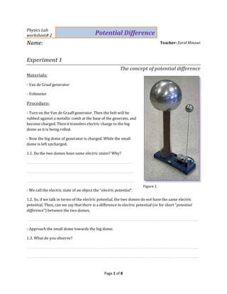
- Van de Graaf generator
- Voltmeter
Procedure:
- Turn on the Van de Graaff generator. Then the belt will be
rubbed against a metallic comb at the base of the generato, and
become charged. Then it transfers electric charge to the big
dome as it is being rolled.
- Now the big dome of generator is charged. While the small
dome is left uncharged.
1.1. Do the two domes have same electric states? Why?
……………………………………………………………………………………………
……………………………………………………………………………………………
……………………………………………………………………………………………
- We call the electric state of an object the “electric potential”.
1.2. So, if we talk in terms of the electric potential, the two domes do not have the same electric
potential. Then, can we say that there is a difference in electric potential (or for short “potential
difference”) between the two domes.
…………………………………………………………………………………………………………………………………………………...
- Approach the small dome towards the big dome.
1.3. What do you observe?
…………………………………………………………………………………………………………………………………………………...
…………………………………………………………………………………………………………………………………………………...
Figure 1
2. Page 2 of 8
1.4. Interpret this observation.
…………………………………………………………………………………………………………………………………………………...
…………………………………………………………………………………………………………………………………………………...
1.5. Can we say that an electric current has flown between the two domes?
…………………………………………………………………………………………………………………………………………………...
1.6. From this experiment, we conclude that: (choose the correct statement or statements)
[ ] an electric current can only flow between two objects or places of different electric states.
[ ] an electric current can only flow between two objects or places, where there is a potential
difference between these two objects or places.
[ ] a potential difference always produces an electric current.
[ ] electric charges can only flow between two objects or places of different electric states.
[ ] electric charges can only flow between two objects or places, where there is a potential
difference between these two objects or places.
[ ] Potential difference is the flow of electric charges.
- We can get a quantitative measure of the potential difference between the two domes using the
voltmeter.
- Connect the positive terminal (or V-terminal) of the voltmeter to the big dome and the negative
terminal of the voltmeter (or COM-terminal) to the small dome.
1.7. What is the voltmeter’s indication?
…………………………………………………………………………………………………………………………………………………...
1.8. What is the unit of the potential difference?
…………………………………………………………………………………………………………………………………………………...
- Remark: Another name of the potential difference is the “voltage”.
1.9. Invert the terminals of the voltmeter. What do you notice?
…………………………………………………………………………………………………………………………………………………...
- Let us represent the potential of the big dome by VA, and that of the small dome by VB. Then the
potential difference from the big dome to the small dome is VA-VB=VAB, and the potential difference
from the small dome to the big dome is VB-VA=VBA.
3. Page 3 of 8
1.10. Deduce the value of VAB and the value of VBA.
…………………………………………………………………………………………………………………………………………………...
1.11. Can you deduce which dome has a greater electric potential? Explain your answer.
…………………………………………………………………………………………………………………………………………………...
…………………………………………………………………………………………………………………………………………………...
Experiment 2
Sign of the potential difference
Materials:
- Voltage source
- Lamp
- Switch
- Voltmeter
Procedure:
- Set up the circuit of figure 2.
- Connect the terminals of the voltmeter to A
and B such that its V- terminal is on A and its
COM-terminal is on B (figure 2).
2.1. What voltage are we measuring? VAB or
VBA?
………………………………………………………………
2.2. Close the switch. What is the voltmeter's indication?
…………………………………………………………………………………………………………………………………………………...
- Interchange the voltmeter's terminals (V-terminal on B and COM-terminal on A).
2.3. Now what voltage are we measuring? VAB or VBA?
…………………………………………………………………………………………………………………………………………………...
2.4. What is the voltmeter's indication again?
…………………………………………………………………………………………………………………………………………………...
Figure 2
4. Page 4 of 8
2.5. Compare the two readings, what do you notice?
…………………………………………………………………………………………………………………………………………………...
2.6. Deduce which terminal of the battery is of greater (or higher) potential. Explain.
…………………………………………………………………………………………………………………………………………………...
…………………………………………………………………………………………………………………………………………………...
2.7. From this experiment, we conclude that: (choose the correct statement or statements)
[ ] when we interchange the terminals of the voltmeter, it displays the same previous number, but
with opposite sign.
[ ] when we interchange the terminals of the voltmeter, we get wrong reading of the potential
difference.
[ ] the potential difference VAB = -VBA.
[ ] the potential difference from A to B is opposite to that from B to A.
Experiment 3
Potential difference between the terminals of a connecting wire
Materials:
- The same as
experiment 2
Procedure:
- Set up the same
circuit in experiment
2.
- Open the switch.
- Connect the
voltmeter to the
terminals of any connection wire (Figure 3).
3.1. What component’s voltage are we measuring?
…………………………………………………………………………………………………………………………………………………...
3.2. What is the voltmeter's indication?
…………………………………………………………………………………………………………………………………………………...
Figure 3
5. Page 5 of 8
3.3. Now close the switch and read the voltmeter's indication again.
…………………………………………………………………………………………………………………………………………………...
3.4. From this experiment, we conclude that: (choose the correct statement or statements)
[ ] the potential difference across any connecting wire is zero or approximately zero.
[ ] the potential difference across any connecting wire is always equal to that of the battery.
[ ] the voltmeter can’t read the potential difference across a connecting wire.
[ ] the connecting wire takes no voltage (or approximately no voltage) and no electric current.
[ ] the connecting wire takes no voltage (or approximately no voltage), it only passes the electric
current.
Experiment 4
Potential difference across the terminals of a switch
Materials:
- The same as experiment 2
Procedure:
- Set up the same circuit as in experiment
2, except that the voltmeter is connected
across the terminals of the switch as
shown in figure 4.
- Close the switch and measure the
potential difference across its terminals
using a voltmeter (Figure 4).
4.1. What is the voltmeter's indication?
…………………………………………………………………………………………………………………………………………………...
- Open the switch and measure the potential difference across its terminals again.
4.2. What is the voltmeter's indication?
…………………………………………………………………………………………………………………………………………………...
4.3. From this experiment, we conclude that: (choose the correct statement or statements)
- The voltage (potential difference) across a closed switch:
Figure 4
6. Page 6 of 8
[ ] is zero or almost zero.
[ ] is equal (or approximately equal) to that of the voltage source.
- The voltage (potential difference) across an open switch:
[ ] is non-zero.
[ ] is equal (or approximately equal) to that of the voltage source.
[ ] A closed switch acts as a connecting wire, while an open switch acts as a voltage source.
[ ] An open switch acts as a connecting wire, while a closed switch acts as a voltage source.
Experiment 5
Potential difference across the terminals of a generator
Materials:
- As in experiment 2.
Procedure:
- Set up the same circuit as in experiment 2,
except that the voltmeter is connected across the
terminals of the generator as shown in figure 5.
- Start with the switch being open.
5.1. What is the voltmeter's indication?
………………………………………………………………………
………………………………………………………………………
- Now, close the switch and read again the
voltmeter's indication.
5.2. What is the voltmeter's indication?
…………………………………………………………………………………………………………………………………………………...
5.3. From this experiment, we conclude that: (choose the correct statement or statements)
[ ] when a current is drawn from the voltage source (e.g. battery), the voltage (potential difference)
across it is slightly less than when there is no current drawn.
[ ] when a current is drawn from the voltage source (e.g. battery), the voltage (potential difference)
across it is slightly greater than when there is no current drawn.
Figure 5
7. Page 7 of 8
[ ] when the switch that is connected in series with the voltage source is open, the voltage
(potential difference) across the voltage source is slightly greater than when the switch is closed.
[ ] when the switch that is connected in series with the voltage source is open, the voltage
(potential difference) across the voltage source is slightly less than when the switch is closed.
Experiment 6
Verification of the law of addition of potential differences
Materials:
- Voltage source
- Switch K
- Three lamps L1, L2, L3
- Voltmeter V
Procedure:
- Set up the circuit of (Figure 6).
- The lamps L1, L2, L3 are placed one after
the other, as shown in figure 6.
6.1. What do we call this grouping?
…………………………………………………………………………………………………………………………………………………...
6.2. Measure the potential differences V1, V2, V2, and VG (VG is the potential difference across the
generator), using the voltmeter.
…………………………………………………………………………………………………………………………………………………...
…………………………………………………………………………………………………………………………………………………...
6.3. Calculate the sum V1+V2+V3
…………………………………………………………………………………………………………………………………………………...
…………………………………………………………………………………………………………………………………………………...
6.4. Compare the result of V1+V2+V3 to VG. what do you notice?
…………………………………………………………………………………………………………………………………………………...
6.5. From this experiment, we conclude that: (choose the correct statement or statements)
[ ] in series circuit, the voltage is additive.
Figure 6
8. Page 8 of 8
[ ] in series circuit, the voltage of the generator is equal to the sum of the voltages of the electrical
components.
[ ] in series circuit, the total voltage across a number of components is equal to the sum of the
voltages of each component.
[ ] in series circuit, we have: Vtotal = V1 + V2 + V3 + …
Experiment 7
Verification of the law of uniqueness of potential difference
Materials:
- Same components as in experiment 6
Procedure:
- Set up the circuit of figure 7.
- Connect the three lamps L1, L2, and L3 to the battery as shown in
figure 7.
7.1. What do we call this grouping?
…………………………………………………………………………………………………
7.2. Measure the voltages V1, V2, V3 and VG
…………………………………………………………………………………………………
…………………………………………………………………………………………………
…………………………………………………………………………………………………
…………………………………………………………………………………………………
7.3. Compare these voltages, what do you notice?
…………………………………………………………………………………………………
…………………………………………………………………………………………………
7.4. From this experiment, we conclude that: (choose the correct statement or statements)
[ ] in parallel circuit, the voltage is the same (is unique).
[ ] in parallel circuit, the voltage of any branch is equal to the voltage of the generator.
[ ] in parallel circuit, we have: VG = V1 = V2 = V3 = …
Figure 7
![Page 2 of 8
1.4. Interpret this observation.
…………………………………………………………………………………………………………………………………………………...
…………………………………………………………………………………………………………………………………………………...
1.5. Can we say that an electric current has flown between the two domes?
…………………………………………………………………………………………………………………………………………………...
1.6. From this experiment, we conclude that: (choose the correct statement or statements)
[ ] an electric current can only flow between two objects or places of different electric states.
[ ] an electric current can only flow between two objects or places, where there is a potential
difference between these two objects or places.
[ ] a potential difference always produces an electric current.
[ ] electric charges can only flow between two objects or places of different electric states.
[ ] electric charges can only flow between two objects or places, where there is a potential
difference between these two objects or places.
[ ] Potential difference is the flow of electric charges.
- We can get a quantitative measure of the potential difference between the two domes using the
voltmeter.
- Connect the positive terminal (or V-terminal) of the voltmeter to the big dome and the negative
terminal of the voltmeter (or COM-terminal) to the small dome.
1.7. What is the voltmeter’s indication?
…………………………………………………………………………………………………………………………………………………...
1.8. What is the unit of the potential difference?
…………………………………………………………………………………………………………………………………………………...
- Remark: Another name of the potential difference is the “voltage”.
1.9. Invert the terminals of the voltmeter. What do you notice?
…………………………………………………………………………………………………………………………………………………...
- Let us represent the potential of the big dome by VA, and that of the small dome by VB. Then the
potential difference from the big dome to the small dome is VA-VB=VAB, and the potential difference
from the small dome to the big dome is VB-VA=VBA.](data:image/gif;base64,R0lGODlhAQABAIAAAAAAAP///yH5BAEAAAAALAAAAAABAAEAAAIBRAA7)