Apidays New York 2024 - Scaling API-first by Ian Reasor and Radu Cotescu, Adobe
Kollmorgen pma with_pc800_ specsheet
1. 14
S E R V O S Y S T E M S
P a c i f i c S c i e n t i f i c P M A & P C 8 0 0 / P C E 8 0 0 S y s t e m s
SYSTEM OVERVIEW
www.DanaherMotion.com•815-226-2222
PC800/PCE800 SERIES DRIVES SEE PAGES 18-21
The PC800 and PCE800 Series are the next generation of Pacific
Scientific’s all-digital brushless servo drives. They provide a
cost-effective, high-performance alternative to previous generation drives
in a package 40% smaller than equivalent older servos.
The PC800 uses 240 VAC input power. The new PCE800 family uses
480 VAC input power for global acceptance of your machine.
These drives use a single DSP to close the current, velocity, and position
loops. All system and application parameters are set in software to insure
repeatability and eliminate drift. The PC800 Family is available in multiple
power levels, all with integral power supplies. The drives comply with the
CE low-voltage directive without requiring additional isolation.
Like all Pacific Scientific drives, the PC/PCE800 Series can accept either
step and direction or analog commands. Motion profiling is standard –
the PC/PCE800 Series' internal profile generator allows pre-set index
moves. The PC/PCE800 Series features Pacific Scientific's patented,
24-bit DRDC (Digital Resolver to Digital Conversion) algorithm to provide
the smoothest low-speed performance in its class and position accuracy
as low as five arc seconds. And, its 400 Hz velocity-loop bandwidth is the
highest in the industry. These features bring you the utmost in simplified
drive set-up and tuning for complicated mechanical systems. Advanced
tuning also allows systems to settle quickly.
Now manufacturers around the world can take advantage of SERCOS
(Serial Real-time Communications System) technology with the
PC/PCE840 Series digital brushless servo drives. The PC/PCE840 Series
brings you the same quality, reliability and performance you've come to
expect from Pacific Scientific and now it delivers the capability to utilize
the enhanced digital two-way control and drive communication
capabilities of SERCOS interface™.
Using the latest SERCOS816 ASIC, the PC/PCE840 Series delivers
network communication rates for distributed motion control up to 16
MHz. The PC/PCE840 Series complies with IEC/EN 61491, the industry's
only open control standard, assuring integration with controls or devices
supporting SERCOS. Its noise-immune fiber-optic cable and ring network
topology greatly reduce wiring costs, installation and set-up time, and
speed tuning and troubleshooting by supporting a rich set of diagnostic
capabilities.
PMA SERIES MOTORS SEE PAGE 16
The PMA Series of brushless servomotors delivers a comprehensive line of rugged,
cost effective servomotors. Covering frame sizes from 55 mm square to 190 mm
square and a continuous rated torque of 0.21 to 54 N-m, these motors offer an
economic means to satisfy the requirements of your application. Standard IP65
sealing and the availability of IP67 washdown duty as an option on selected models
allows the PMA Series to stand up to the rigors of the factory floor. Global
certifications and input voltages on most models to 650 volts assure your machine's
acceptance worldwide.
System torque/speed information on the following pages is designed to help you select the optimum
brushless servo motor/controller combination.
The nominal values in this data illustrate performance for the recommended motor/controller systems.
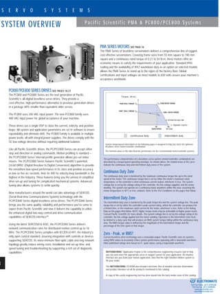
The performance characteristics of a brushless servo system (motor/controller combination) are
described by a torque/speed operating envelope. As shown above, the shaded areas of the curve
indicate the continuous duty and intermittent duty zones of the system.
Continuous Duty Zone
The continuous duty zone is bordered by the maximum continuous torque line up to the rated
speed of the motor. The continuous torque line is set by either the motor’s maximum rated
temperature, or the controller’s rated continuous current output, whichever is less. The system
voltage line is set by the voltage rating of the controller, the line voltage supplied, and the motor
winding. The system can operate on a continuous basis anywhere within this area, assuming the
motor temperature is 40°C or less, ambient. Refer to the Test Conditions on the pages that follow.
Intermittent Duty Zone
The intermittent duty zone is bordered by the peak torque line and the system voltage line. The peak
torque line is set by either the controller’s peak current rating, which the controller can produce for
a limited time, or the maximum rated current for the motor, whichever is less. Refer to the Rating
Data on the pages that follow. NOTE: higher torque levels may be achievable at higher power levels.
Consult Pacific Scientific for more details. The system voltage line is set by the voltage rating of the
controller, the line voltage applied and the motor winding. Operation in the intermittent zone must
be limited to a duty cycle that will produce an RMS system torque falling within the continuous duty
area. The RMS torque value is defined by the magnitude of the intermittent torque and the
percentage of the time spent at that torque.
Zero - Peak, or RMS?
Current brushless drive technology uses a sinusoidal output. Pacific Scientific rates its systems
using RMS values to accurately reflect system performance operating with a sinusoidal waveform.
Older published ratings were based on 0 - peak values, using a trapezoidal waveform.
Torque (N-m)
Speed (rpm)
continuous duty intermittent duty
NL
NO LOAD
SYSTEM VOLTAGE LINE
MOTIONEERING®
Application Engine is the comprehensive engineering resource tool to help
you size and select the appropriate servo or stepper system for your application. An intuitive
interface lets you build your motion application, then find the right Danaher Motion system to
fill your needs.
The MOTIONEERING CD-ROM also includes electronic files of detailed selection information
and product literature on all the products mentioned in this catalog.
A copy of this useful engineering tool has been bound into the back inside cover of this catalog.
ELECTROMATE
Toll Free Phone (877) SERVO98
Toll Free Fax (877) SERV099
www.electromate.com
sales@electromate.com
Sold & Serviced By:
3. KEY A 10x8x50 DIN 6885
CUSTOMER KEY OPTION
4
49.70
50.00
35
(.16)
(1.96)
(1.97)
(1.38)
BenefitsFeatures
PMA Series Motors
Rugged Brushless Construction
High torque over wide speed range
Anti-cog motor design
IP65 TENV construction standard
IP67 protection on selected PMA
models
Class H insulation
Overtemperature thermistor
Multiple feedback options
Brake option
Neodymium-iron-boron magnets
High quality Interconnectron
connectors
High voltage models available
Global approvals and agency
recognition
Two year warranty
Eliminates brush replacement
maintenance. Stands up to the rigors
of the factory floor
Improved machine throughput
Smooth low-speed operation
Withstands rigorous environments
Withstands washdown
Longer life for reduced machine
downtime
Protection against motor damage
Allows numerous control methods
Improved machine safety
Maximum performance, maximum
value
Faster installation and maintenance
Improved application flexibility
Eases recognition process for a
machine
Quality and reliability for reduced
machine downtime
16
S E R V O S Y S T E M S
P a c i f i c S c i e n t i f i c P M A & P C 8 0 0 / P C E 8 0 0 S y s t e m s
PMA MOTORS
www.DanaherMotion.com•815-226-2222
Motor PMA42 PMA43 PMA44 PMA45
L 185 (7.3) 210 (8.3) 235 (9.2) 260 (10.2)
4 ± 0.3
(.16 ± .01)
15 ± 1
(.59 ± .04)
Ø 14 ( x4 )
(Ø .55 ( x4 ))
Ø 215
(Ø 8.45)
Ø180-6
Ø32+6(Ø7.08-.24)
DR M12 DIN 332
CENTRE HOLE
( L ) MAX.SQ.190
(SQ.7.47) 58 ± 0.5
(2.28 ± .02)
6 MAX.
.24 MAX.
45°
58
(2.28)
17
(.67)
(Ø1.26+.24)
41.5
(1.63)
50
(1.97)
PMA2 SERIES MOTOR
mm (in)
PMA6 SERIES MOTOR
mm (in)
23
(.90)
Ø 5.8 ( x4 )
(Ø .23 ( x4 ))
Ø 85
(Ø 3.34)
45°
8 ± 1
(.31 ± .04)
2.5 ± 0.3
(.1 ± .01)
Ø 11 + 6
Ø 60 - 6
(Ø 2.36 - .24)
( L ) MAX.
23 ± 0.5
(.90 ± .02)
43
(1.69)
6
(.24)
SQ.70
(SQ.2.75)
DR M4 DIN 332
CENTRE HOLE
Ø11k6
(0.4335)
(0.4332)
40
(1.57)
45°
Ø 130
(5.11)
10 MAX.
(.39 MAX.)
( L ) MAX.
Ø 9 ( x4 )
(.35 ( x4 ))
9 ± 1
(.35 ± .04)
3.5 ± 0.3
(.14 ± .01)
DR M6 DIN 332
CENTRE HOLE
Ø19+6
(75+.24)
Ø110-6
(4.32-.24)
SQ.115
(SQ.4.52)
41.5
(1.63)
18
(.71)
40 ± 0.5
(1.57 ± .02)
DR M8 DIN 332
CENTRE HOLE
3.5 ± 0.1
.14 ± 0.1)Ø 130 -6
(Ø 5.11 -.24 )
12 ± 1
(47 ± .04)
Ø 165
Ø 6.49
50 ± 0.5
(1.97 ± .02)
10 MAX.
(.39 MAX.)
( L ) MAX.
Ø24+6
(Ø.94+.24)
Ø 11 ( x4 )
(Ø .43 ( x4 ))
45°
SQ.142 (SQ.5.58)
50
(1.97)
41.5
(1.63)
18
(.71)
(
12.5
(.49)
3.5
(.14)
15.8
16.0
(.62)
(.63)
CUSTOMER KEY OPTION
KEY A 4x4x16 DIN 6885
Motor PMA53 PMA54 PMA55 PMA57
L 205 (8.1) 230 (9.0) 255 (10.0) 305 (12.0)
Motor PMA21 PMA22 PMA23 PMA24
L 145 (5.6) 168 (6.6) 193 (7.6) 218 (8.6)
21.5
(.85)
31.7
32.0
(1.25)
(1.26)
5
(.20)
KEY A 6x6x32 DIN 6885
CUSTOMER KEY OPTION
KEY A 8x7x40 DIN 6885
CUSTOMER KEY OPTION
5
39.70
40.00
(1.56)
(1.57) 27
(1.06)
(.20)
[1.79]
[.3544]
[.3547]
[1.5752]
[2.323]
[.19]
[SQ 2.17]
[2.48]
[.31 ± .04]
[.10 ± .01]
[.787 ± 0.02]
45.5
[1.5746][ø9k6]
ø40j6
20 ± 0.5 Brake adds 25 mm
DR M3 DIN 332
CENTRE HOLE
8 ± 1
2.5 ± 0.3
SQ.55
45°
59
4.8 (x4)
ø 63
[.787]
20
(L)
Motor PMA65 PMA66 PMA67 PMA69
L 295 (11.6) 320 (12.6) 345 (13.6) 395 (15.6)
Motor PMA13 PMA12 PMA11
L 175 (6.89) 150 (5.906) 125 (4.921)
PMA1 SERIES MOTOR
mm (in)
PMA4 SERIES MOTOR
mm (in)
PMA5 SERIES MOTOR
mm (in)
ELECTROMATE
Toll Free Phone (877) SERVO98
Toll Free Fax (877) SERV099
www.electromate.com
sales@electromate.com
Sold & Serviced By:
4. 17
S E R V O S Y S T E M S
www.DanaherMotion.com•815-226-2222
PMA5-6SERIESMOTORSPMA1-2SERIESMOTORS
RATINGS AND CHARACTERISTICS
Motor parameters and winding data. See system data beginning on page 15 for typical torque/speed performance.
PARAMETER SYMBOL UNITS PMA11 PMA12 PMA13 PMA21 PMA22 PMA23 PMA24
Continuous stall torque ➀ ➁ TCS N-m (lb-in) 0.26 (2.3) 0.6 (5.3) 0.9 (8.0) 0.63 (5.6) 1.3 (11.5) 2 (17.7) 2.6 (23.0)
Peak torque ➂ ➃ TPK N-m (lb-in) 1.4 (12.4) 2.9 (25.6) 4.3 (38.0) 2.3 (20.4) 4.7 (41.6) 7.2 (63.7) 9.6 (85.0)
Inertia ➄ ➅ JM kgm2
x10-3
(lb-in-sec2
x10-3
) 0.012 (0.102) 0.019 (0.164) 0.026 (0.226) 0.022 (0.19) 0.038 (0.34) 0.055 (0.49) 0.072 (0.64)
Static friction (max.) Tf N-m (lb-in) 0.008 (0.071) 0.012 (0.106) 0.018 (0.160) 0.016 (0.14) 0.033 (0.29) 0.050 (0.44) 0.065 (0.58)
Viscous damping coefficient KDV N-m/krpm (lb-in/krpm) 0.001 (0.009) 0.002 (0.018) 0.003 (0.027) 0.003 (0.03) 0.006 (0.05) 0.009 (0.08) 0.012 (0.11)
Thermal resistance RTH deg. C/watt 3.1 2.0 1.6 1.83 1.41 1.13 0.89
Thermal time constant tTH min 10.0 13.0 16.0 13.0 15.0 18.0 20.0
Weight (motor only) W kg (lbs) 1.2 (2.6) 1.5 (3.3) 1.9 (4.2) 1.7 (3.7) 2.3 (5.0) 2.9 (6.4) 3.5 (7.7)
WINDING DATA A A B B B B-D C-D
Torque constant (RMS) Kr N-m/ARMS (lb-in/ARMS) 0.27 (2.38) 0.32 (2.85) 0.33 (2.90) 0.37 (3.3) 0.49 (4.3) 0.74 (6.5)-0.4 (3.5) 0.79 (7.0)-0.5 (4.41)
Voltage constant (RMS) (l-l) KE VRMS/rad/sec (VRMS/krpm) 0.16 (17.2) 0.20 (20.6) 0.20 (21.0) 0.23 (24.0) 0.30 (31.2) 0.45 (47.4)-0.24 (25.4) 0.49 (50.9)-0.31 (31.9)
Continuous stall current ➀ ➁ ICS ARMS 0.96 1.88 2.73 1.72 2.65 2.7-5.0 3.3-5.3
Current at peak torque ➃ IPK ARMS 5.3 9.4 13.8 6.88 10.6 10.8-20.0 13.2-21.2
Resistance (line-to-line) RC ohms 16.3 6.8 3.9 8.8 4.81 6.1-1.7 4.6-1.9
Inductance (line-to-line) L mH 7.1 4.3 2.7 10.5 7.4 10.6-3.0 8.9-3.5
Typical Rated Speed
@ 240 VAC, 320 VDC bus WR rpm 6,600 8,500 9,000 6,050 4,650 3,600-6,400 3,000-4,950
Typical Rated Torque
@ 240 VAC, 320 VDC bus TCR N-m (lb-in) 0.22 (1.9) 0.48 (4.2) 0.60 (5.3) 0.5 (4.4) 1.06 (9.4) 1.7 (14.6)-1.4 (12.4) 2.2 (19.5)-2.2 (19.5)
PARAMETER SYMBOL UNITS PMA42 PMA43 PMA44 PMA45 PMA53 PMA54
Cont. stall torque➀ ➁ TCS N-m (lb-in) 4.1 (36.3) 6.1 (54.0) 8.2 (72.6) 10.2 (90.3) 10.5 (92.9) 13.5 (120)
Peak torque ➂ ➃ TPK N-m (lb-in) 14.6 (129) 21.7 (192) 29.4 (260) 36.8 (326) 31.0 (274) 41.0 (363)
Inertia ➄ ➅ JM
kgm2x10-3
(lb-in-sec2x10-3) 0.36 (3.2) 0.52 (4.6) 0.68 (6.0) 0.84 (7.4) 1.92 (17) 2.49 (22)
Static friction (max.) Tf N-m (lb-in) 0.11 (1.0) 0.15 (1.3) 0.21 (1.9) 0.26 (2.3) 0.26 (2.3) 0.34 (3.0)
Viscous damping KDV N-m/krpm
coefficient (lb-in/krpm) 0.03 (0.27) 0.05 (0.44) 0.06 (0.53) 0.08 (0.71) 0.08 (0.71) 0.11 (0.97)
Thermal resistance RTH deg. C/watt 0.68 0.59 0.51 0.45 0.55 0.53
Thermal time constant tTH min 25.0 30.0 35.0 40.0 35.0 40.0
Weight (motor only) W kg (lbs) 6.2 (13.6) 7.6 (16.7) 9.0 (20.0) 10.4 (22.9) 11 (24.2) 13.0 (28.6)
WINDING DATA M-N-P-Q N-P-Q-R N-P-Q-R N-Q-R Q-R Q-R
Torque constant (RMS) Kr N-m/ARMS 1.48 (13.1)-1.11 (9.8) 1.67 (14.8)-1.34 (11.9) 2.26 (20.0)-1.34 (11.9) 2.85 (25.2)-1.46 (12.9)
(lb-in/ARMS) 0.87 (7.7)-0.63 (5.6) 0.85 (7.5)-.61 (5.4) 1.15 (10.2)-0.82 (7.3) 1.04 (9.2) 1.55 (13.7)-1.08 (9.6) 1.9 (16.8)-1.27 (11.3)
Voltage constant (RMS) KE VRMS/rad/sec 0.91 (94.8)-0.68 (7.1) 1.02 (107)-0.82 (86.1) 1.38 (145)-0.94 (98.8) 1.74 (183)-0.89 (93.4)
(l-l) (VRMS/krpm) 0.53 (55.8)-0.39 (40.6) 0.52 (54.9)-0.37 (39.2) 0.71 (74)-0.5 (52.8) 0.64 (66.7) 0.95 (99.3)-0.66 (69.2) 1.16 (122)-0.78 (81.5)
Cont. stall current ➀ ➁ ICS ARMS 2.8-3.7-4.7-6.5 3.7-4.6-7.2-10.1 3.6-5.4-7.2-10.1 3.6-7.1-10.0 6.8-9.7 7.1-10.6
Current at peak torque ➃ IPK ARMS 11.2-14.8-18.8-26.0 14.8-18.4-28.8-40.4 14.4-21.6-28.8-40.4 14.4-28.4-40.0 27.2-38.8 28.4-42.4
Resistance (line to line) RC ohms 9.0-5.1-3.2-1.65 6.0-3.9-1.54-0.79 7.1-3.3-1.8-0.92 8.2-2.1-1.1 1.9-0.92 1.8-0.8
Inductance (line to line) L mH 26.0-14.3-8.9-4.7 20.0-13.0-5.3-2.7 27.0-12.4-7.1-3.6 33.0-8.7-4.4 15.0-7.2 16.0-7.1
Typical Rated Speed 1,600-1,950 1,250-1,850 850-1,750 600-1,650
@ 240 VAC, 320 VDC bus WR rpm 2,950-3,800 3,000-4,700 2,100-3,450 2,700 1,300-2,350 1,200-2,100
Typical Rated Torque 3.9 (34.5)-3.8 (33.6) 5.8 (51.3)-5.6 (49.6) 7.9 (70.0)-7.5 (66.4) 9.9 (87.6)-9.4 (83.2)
@ 240 VAC, 320 VDC bus TCR N-m (lb-in) 3.6 (31.9)-34.0 (30.1) 5.2 (46.0)-4.5 (39.8) 7.3 (64.4)-6.7 (59.3) 8.9 (78.8) 9.6 (85.0)-8.8 (77.9) 12.4 (110)-11.6 (102.7)
PARAMETER SYMBOL UNITS PMA55 PMA57 PMA65 PMA66 PMA67 PMA69
Cont. stall torque ➀ ➁ TCS N-m (lb-in) 17.0 (151) 22.0 (195) 30.0 (266) 36.0 (319) 42.0 (372) 54.0 (478)
Peak torque ➂ ➃ TPK N-m (lb-in) 51.5 (456) 69.0 (611) 95.0 (841) 114 (1009) 133 (1177) 170 (1505)
Inertia ➄ ➅ JM kgm2
x10-3
(lb-in-sec2
x10-3
) 3.06 (27.1) 4.21 (37.3) 7.90 (70.0) 9.40 (83.3) 10.9 (96.5) 13.9 (123)
Static friction (max.) Tf N-m (lb-in) 0.43 (3.8) 0.57 (5.0) 0.75 (6.60) 0.90 (8.0) 1.05 (9.30) 1.35 (11.9)
Viscous damping coefficient KDV N-m/krpm (lb-in/krpm) 0.14 (1.24) 0.18 (1.59) 0.25 (2.20) 0.30 (2.70) 0.35 (3.10) 0.45 (4.0)
Thermal resistance RTH deg. C/watt 0.47 0.45 0.38 0.35 0.32 0.28
Thermal time constant tTH min 45.0 55.0 40.0 45.0 50.0 60.0
Weight (motor only) W kg (lbs) 15.0 (33.0) 19.0 (41.9) 31.0 (68.3) 36.0 (79.3) 42.0 (92.5) 54.0 (119)
WINDING DATA Q-R-S R-S R-S R-S S S
Torque constant (RMS) Kr N-m/ARMS 2.4 (21.3)-0.8 (7.1)
(lb-in/ARMS) 0.8 (7.1) 2.26 (20)-1.13 (10) 2.66 (23.5)-1.44 (12.7) 3.21 (28.5)-1.74 (15.4) 2.04 (18.0) 2.63 (23.3)
Voltage constant (RMS) (l-l) KE VRMS/rad/sec 1.47 (154)-0.98 (103)
(VRMS/krpm) 0.49 (51.3) 1.38 (145)-0.69 (72.5) 1.63 (171)-0.88 (92.3) 1.96 (206)-1.06 (112) 1.25 (131) 1.61 (169)
Continuous stall current ➀ ➁ ICS ARMS 7.1-10.6-21.3 9.8-19.5 11.3-20.9 11.3-20.7 20.7 20.6
Current at peak torque ➃ IPK ARMS 28.4-42.4-85.2 39.2-78.0 45.2-83.6 45.2-82.8 82.8 82.4
Resistance (line-to-line) RC ohms 2.1-0.9-0.2 1.1-0.3 0.97-0.29 1.06-0.32 0.35 0.41
Inductance (line-to-line) L mH 20.0-8.8-2.2 12.5-3.1 20.0-5.90 24.0-7.0 8.2 10.4
Typical Rated Speed
@ 240 VAC, 320 VDC bus WR rpm 900-1,650-3,450 1,150-2,450 N/A-1,750 N/A-1,450 1,250 950
Typical Rated Torque 16.0 (142)-15.2 (134.5)
@ 240 VAC, 320 VDC bus TCR N-m (lb-in) 3.1 (115.9) 20.5 (181.4)-18.4 (162.9) N/A-24.5 (216.8) N/A-31.0 (274) 37.0 (327) 48.5 (429)
PMA4-5SERIESMOTORS
Note: All values at 25°C unless otherwise noted.
➀ Motor operated at rated winding temperature rise of ∆t = 100°C above ambient at 25°C ambient. Ratings result of average rating between free air and cold plate mounting. Equivalent to mounting to
a 10" x 10" x 1/4" aluminum heat sink. | ➁ All tests performed with sinusoidal commutation. | ➂ Theoretical motor maximum. | ➃ Caution: For peak torques or peak currents greater than 4x
the continuous rating, consult the factory for thermal considerations. | ➄ Add parking brake, if applicable, for total inertia from product selection data. See CD-ROM. | ➅ Motor with resolver feedback.
ELECTROMATE
Toll Free Phone (877) SERVO98
Toll Free Fax (877) SERV099
www.electromate.com
sales@electromate.com
Sold & Serviced By:
5. 18
S E R V O S Y S T E M S
P a c i f i c S c i e n t i f i c P M A & P C 8 0 0 / P C E 8 0 0 S y s t e m s
PC800 DRIVES
www.DanaherMotion.com•815-226-2222
PC800 SERIES PERFORMANCE FEATURES
• 240 VAC nominal input power
• 2.7, 3.6 and 7.1 ARMS continuous
• 5.3, 10.6 and 21.2 ARMS peak output current
• Standard analog and digital interfaces
– Step/Direction Digital interface-position or velocity control
– Preset moves using an internal profile generator
– ±10 V Analog interface-velocity or torque control
– Quadrature encoder digital interface-electronic gearing follower
• All digital DSP-based RS-232/485 serial interface allows
programming with an IBM-compatible PC
• Simple ASCII Protocol (SAP) compatible with many operator
interfaces
• SERCOS interface™ connectivity offers communications via fiber optic
network at up to 16 MHz
• Windows®
-based 800Tools configuration software simplifies set-up:
– Digital oscilloscope feature quickly shows drive function graphically
– Intuitive parameter configuration-up and running in minutes
– Advanced digital tuning for reduced settling time
– All system and application parameters are set and saved
– Automated diagnostic routine reduces troubleshooting time
• Rugged, PLC-like digital and analog I/O maximize application
flexibility:
– Six optically-isolated inputs
– Three optically-isolated outputs
– One relay output, 30 VDC @ 1A
– Differential ±10 V analog input
– Single-end analog input, ±5 VDC
– Two analog outputs, ±5 VDC
– Encoder quadrature output-up to 16,384 ppr
– Encoder quadrature input (Step/Direction)
– Enable input
– +5 VDC @ 200 mA user output
– +24 VDC @ 100 mA power supply for optically-isolated inputs
• Single resolver feedback survives hostile environments
• Hall/Encoder feedback allows application flexibility, making it suitable
for use with many popular linear motors
• All connections on front-easy access to clearly marked connectors
• Optional Terminal Block Adapter speeds connections even further
• Separate logic supply input keeps logic power working when bus
power is disconnected
• Extensive protection circuits and diagnostics to ease set-up
• 400 Hz velocity loop bandwidth
• Inaudible, high frequency, Digital PWM sine wave current control
• IGBT Power stage- more efficient, less audible noise
AGENCY APPROVAL
• UL recognized
– 508C (Type R)
– file #E137798
• cUL approved
• Meets IEC Vibration Standard, #68-2-6
• Models CE Compliant: EMC standard EN61800-3 and safety standard EN50178
PC8x2 PC8x3 PC8x4
Input Voltage
Control logic voltage 90 - 264 VAC, 47 - 63 Hz, single phase
Bus voltage 90 - 264 VAC, 1 or 3-phase
Input Current
Control logic current 500 mA maximum @120 VAC, 250 mA maximum @240 VAC
PC8x2 PC8x3 PC8x4
Equivalent Equivalent Equivalent
ARMS A0-PEAK ARMS A0-PEAK ARMS A0-PEAK
Bus Current (A) 4.5 6.4 9.0 12.7 18.0 25.5
Peak Output Current (A)
5 seconds 5.3 7.5 10.6 15 21.2 30.0
Continuous Output Current
25 - 40°C convection cooling (A) 2.7 0.8 3.6 5.0 7.1 10.0
25 - 40°C forced air cooling (A) N/A N/A 5.3 7.5 10.6 15.0
Peak Output Power @240 VAC
1 second (kW) 2.25 4.5 9.0
Continuous Output Power
@240 VAC three phase
25 - 40°C convection cooling (kW) 1.1 1.5 3.0
25 - 40°C forced air cooling (kW) N/A 2.2 4.5
@240 VAC single phase
25 - 40°C convection cooling (kW) 1.1 1.1 2.0
25 - 40°C forced air cooling (kW) N/A 1.6 2.0
Power Stage Efficiency @ PCONT (%) 98 98 98
Shunt Regulator Power
Peak power (300 msec) (kW) 12.8 12.8 12.8
Continuous power
25°C convection cooling (W) 200 200 200
Maximum external regen duty cycle (%) 6 6 6
Bus capacitance energy absorption
from 320 V nominal bus (240 VAC) (joules) 20 30 40
AMPLIFIER RATINGS
MOTIONEERING®
CD-ROM
For more detailed product and selection information, see the
MOTIONEERING CD-ROM inside the back cover of this
catalog or visit our website at www.DanaherMotion.com.
ELECTROMATE
Toll Free Phone (877) SERVO98
Toll Free Fax (877) SERV099
www.electromate.com
sales@electromate.com
Sold & Serviced By:
6. 19
S E R V O S Y S T E M S
P a c i f i c S c i e n t i f i c P M A & P C 8 0 0 / P C E 8 0 0 S y s t e m s
PC800 DRIVES
www.DanaherMotion.com•815-226-2222
TERMINAL BLOCK ADAPTOR
mm [in]
FAN KIT OPTION shown without electrical connection cable.
118.1
[ 4.65 ]
57.23
[ 2.253 ]
3.8
[ .15 ]
29.2
[ 1.15 ]
17.15
[ .675 ]
8.3
[ .33 ]
47
[ 1.85 ]
1.57
[ .062 ]
82.04
[ 3.230 ]
25.24
[ .994 ]
18.42
[ .725 ]
31.75
[ 1.250 ]
60
[ 2.36 ]
215
[ 8.46 ]
175
[ 6.89 ]
17
[ .67 ]
6.4
[ .25 ]
202.3
[ 7.96 ]
1.981
[ R .0780 ]
12.7
[ .500 ]
13
[ .51 ]
10
[ .39 ]
FASTEN TAB
PC800 SERIES
mm [in]
REGENERATION RESISTOR
Faceplate detail of PC83x Faceplate detail of PC84x
3.3
[ R.130 ]
44.1
[ 1.74 ]
88.1
[ 3.47 ]
6.6
[ .26 ]
184.91
[ 7.280 ]
198.1
[ 7.80 ]
157.9
[ 6.22 ]
ø
MOUNTING FOR M4
FOR #8-32 TYP 2 PL.
129.4
[ 5.09 ]
7.9
[ .31 ]
101.6
[ 4.00 ]
85.7
[ 3.38 ]
4.37
[ .172 ]
9.5
[ .38 ]
50.8
[ 2.00 ] 56.3
[ 2.22 ]
114
[ 4.49 ]
25.9
[ 1.02 ]
ELECTROMATE
Toll Free Phone (877) SERVO98
Toll Free Fax (877) SERV099
www.electromate.com
sales@electromate.com
Sold & Serviced By: