DevoxxFR 2024 Reproducible Builds with Apache Maven
Kollmorgen nema42 conventional_hybrid_catalog
1. www.pacsci.com68
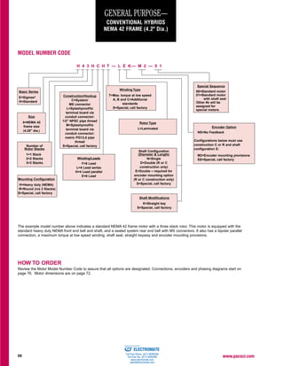
GENERAL PURPOSE—
CONVENTIONAL HYBRIDS
NEMA 42 FRAME (4.2" Dia.)
The example model number above indicates a standard NEMA 42 frame motor with a three stack rotor. This motor is equipped with the
standard heavy duty NEMA front end bell and shaft, and a sealed system rear end bell with MS connectors. It also has a bipolar parallel
connection, a maximum torque at low speed winding, shaft seal, straight keyway and encoder mounting provisions.
HOW TO ORDER
Review the Motor Model Number Code to assure that all options are designated. Connections, encoders and phasing diagrams start on
page 76. Motor dimensions are on page 72.
Basic Series
E=Sigmax®
H=Standard
Size
4=NEMA 42
frame size
(4.28" dia.)
Number of
Rotor Stacks
1=1 Stack
2=2 Stacks
3=3 Stacks
Mounting Configuration
H=Heavy duty (NEMA)
R=Round (n/a 3 Stacks)
S=Special, call factory
Construction/Hookup
C=System/
MS connector
L=Splashproof/to
terminal board via
conduit connector:
1/2" NPSC pipe thread
M=Splashproof/to
terminal board via
conduit connector:
metric PG13,5 pipe
thread
S=Special, call factory
Winding/Leads
F=8 Lead
L=4 Lead series
H=4 Lead parallel
E=6 Lead
Winding Type
T=Max. torque at low speed
A, B and C=Additional
standards
S=Special, call factory
Rotor Type
L=Laminated
Shaft Configuration
(Diameter & Length)
N=Single
D=Double (R or C
construction only)
E=Double – required for
encoder mounting option
(R or C construction only)
S=Special, call factory
Shaft Modifications
K=Straight key
S=Special, call factory
Special Sequence
00=Standard motor
01=Standard motor
with shaft seal
Other #s will be
assigned for
special motors
Encoder Option
NS=No Feedback
Configurations below must use
construction C or R and shaft
configuration E:
M2=Encoder mounting provisions
SS=Special, call factory
MODEL NUMBER CODE
H 4 3 H C H T — L E K— M 2 — 0 1
599-95 Step Mtrs Sel Gd.out 11/15/00 1:45 PM Page 68
ELECTROMATE
Toll Free Phone (877) SERVO98
Toll Free Fax (877) SERV099
www.electromate.com
sales@electromate.com
Sold & Serviced By:
2. www.pacsci.com 69
GENERAL PURPOSE—CONVENTIONAL HYBRIDS
NEMA 42 FRAME (4.2" Dia.)—Ratings and Characteristics
Review the Model Number Code, page 68, to assure that all options are designated. Connections, encoders and
phasing diagrams start on page 76. Motor dimensions are on page 72. In addition to those below, motors with
characteristics for specific performance requirements are offered. Contact factory for more details.
Connection Holding
Torque Phase
Rated Inductance
Current/ Phase Thermal Rotor
Motor (2 phases on) Phase Resistance Detent Resistance Inertia
Model Number oz-in (Nm) (ohms) (mH) Torque oz-in-S2
Weight
±10% (amps DC) ±10% Typical oz-in (Nm) (o
C/watt) (kgm2
x 10-3
) lbs (kg)
E41HXHA-LXX-XX-00 • 1378 (9.73) 10.6 0.16 2.5
E41HXLA-LXX-XX-00 • 1378 (9.73) 5.3 0.64 10.0
E41HXEA-LXX-XX-00 • 974 (6.88) 7.5 0.32 2.5
E41HXHT-LXX-XX-00 • 1353 (9.55) 5.4 0.61 9.0
E41HXLT-LXX-XX-00 • 1353 (9.55) 2.7 2.41 36.1
E41HXET-LXX-XX-00 • 957 (6.76) 3.8 1.21 9.0
E41HXHB-LXX-XX-00 • 1377 (9.72) 5.3 0.64 10.0
E41HXLB-LXX-XX-00 • 1377 (9.72) 2.7 2.54 40.0
E41HXEB-LXX-XX-00 • 974 (6.88) 3.7 1.27 10.0
H41HXHA-LXX-XX-00 • 839 (5.93) 10.6 0.16 3.1
H41HXLA-LXX-XX-00 • 839 (5.93) 5.3 0.64 12.4
H41HXEA-LXX-XX-00 • 593 (4.19) 7.5 0.32 3.1
H41HXHT-LXX-XX-00 • 828 (5.84) 5.4 0.61 11.2
H41HXLT-LXX-XX-00 • 828 (5.84) 2.7 2.41 44.6
H41HXET-LXX-XX-00 • 585 (4.13) 3.8 1.21 11.2
H41HXHB-LXX-XX-00 • 839 (5.92) 5.3 0.64 12.4
H41HXLB-LXX-XX-00 • 839 (5.92) 2.7 2.54 49.4
H41HXEB-LXX-XX-00 • 593 (4.19) 3.7 1.27 12.4
Parallel
Series
Unipolar
Rated currents are in
descending order
Torque range:
957-1378 oz-in.
6.76-9.73 Nm
SIGMAX®
E41 Series
1 rotor stack
58 0.0800 10.9
(0.41)
1.8
(0.565) (4.94)
Torque range:
585-839 oz-in.
4.13-5.93 Nm
STANDARD
H41 Series
1 rotor stack 31 0.0800 10.9
(0.22)
1.8
(0.565) (4.94)
All ratings typical and at 25°C unless otherwise noted.
An “X” in the Model Number Code indicates an undefined
option. Colored letter indicates winding. See How to Order and
Model Number Code on page 68.
Motor connections are determined by the Windings/Leads
designation in the model Number Code on page 68. Note that
the F designation, although not shown in the above tables, is
an 8-lead option...see Terminations, page 76. In addition to the
lead wire termination, terminal board and MS connector hookup
for parallel, series or unipolar operation is also available.
With rated current applied. Windings at 130°C and motor
unmounted and in still air at 40°C (without heat sink).
Windings at 130°C and motor in still air at 40°C (without heat sink).
Operation of these motors above rated current may cause
demagnetization. Contact factory.
Small signal inductance as measured with impedance bridge at
1kHz, 1 amp.
Thermal resistance measured with motor hanging in still air
(unmounted).
599-95 Step Mtrs Sel Gd.out 11/15/00 1:45 PM Page 69
ELECTROMATE
Toll Free Phone (877) SERVO98
Toll Free Fax (877) SERV099
www.electromate.com
sales@electromate.com
Sold & Serviced By:
3. www.pacsci.com70
GENERAL PURPOSE—CONVENTIONAL HYBRIDS
NEMA 42 FRAME (4.2" Dia.)—Ratings and Characteristics (Con’t.)
Connection Holding
Torque Phase
Rated Inductance
Current/ Phase Thermal Rotor
Motor (2 phases on) Phase Resistance Detent Resistance Inertia
Model Number oz-in (Nm) (ohms) (mH) Torque oz-in-S2
Weight
±10% (amps DC) ±10% Typical oz-in (Nm) (o
C/watt) (kgm2
x 10-3
) lbs (kg)
E42HXHC-LXX-XX-00 • 2698 (19.06) 14.7 0.12 2.7
E42HXLC-LXX-XX-00 • 2698 (19.06) 7.4 0.47 10.6
E42HXEC-LXX-XX-00 • 1908 (13.48) 10.4 0.24 2.7
E42HXHB-LXX-XX-00 • 2598 (18.34) 9.8 0.27 5.4
E42HXLB-LXX-XX-00 • 2598 (18.34) 4.9 1.07 21.7
E42HXEB-LXX-XX-00 • 1837 (12.97) 6.9 0.54 5.4
E42HXHT-LXX-XX-00 • 2552 (18.02) 7.9 0.41 7.8
E42HXLT-LXX-XX-00 • 2552 (18.02) 4.0 1.62 31.3
E42HXET-LXX-XX-00 • 1805 (12.75) 5.6 0.81 7.8
E42HXHA-LXX-XX-00 • 2693 (19.02) 5.9 0.74 16.6
E42HXLA-LXX-XX-00 • 2693 (19.02) 2.9 2.96 66.5
E42HXEA-LXX-XX-00 • 1904 (13.45) 4.1 1.48 16.6
H42HXHC-LXX-XX-00 • 1652 (11.66) 14.7 0.12 3.3
H42HXLC-LXX-XX-00 • 1652 (11.66) 7.4 0.47 13.3
H42HXEC-LXX-XX-00 • 1168 ( 8.25) 10.4 0.24 3.3
H42HXHB-LXX-XX-00 • 1604 (11.32) 9.8 0.27 6.8
H42HXLB-LXX-XX-00 • 1604 (11.32) 4.9 1.07 27.2
H42HXEB-LXX-XX-00 • 1134 ( 8.01) 6.9 0.54 6.8
H42HXHT-LXX-XX-00 • 1581 (11.17) 7.9 0.41 9.8
H42HXLT-LXX-XX-00 • 1581 (11.17) 4.0 1.62 39.2
H42HXET-LXX-XX-00 • 1118 ( 7.90) 5.6 0.81 9.8
H42HXHA-LXX-XX-00 • 1649 (11.65) 5.9 0.74 20.8
H42HXLA-LXX-XX-00 • 1649 (11.65) 2.9 2.96 83.4
H42HXEA-LXX-XX-00 • 1166 ( 8.24) 4.1 1.48 20.8
Parallel
Series
Unipolar
Rated currents are in
descending order
Torque range:
1805-2698 oz-in.
12.75-19.06 Nm
SIGMAX®
E42 Series
2 rotor stacks
81 0.1600 18.2
(0.57)
1.3
(1.129) (8.26)
Torque range:
1118-1652 oz-in.
7.90-11.66 Nm
STANDARD
H42 Series
2 rotor stacks
All ratings typical and at 25°C unless otherwise noted.
An “X” in the Model Number Code indicates an undefined
option. Colored letter indicates winding. See How to Order and
Model Number Code on page 68.
Motor connections are determined by the Windings/Leads
designation in the Model Number Code on page 68. Note that
the F designation, although not shown in the above tables, is
an 8-lead option...see Terminations, page 76. In addition to the
lead wire termination, terminal board and MS connector hookup
for parallel, series or unipolar operation is also available.
With rated current applied. Windings at 130°C and motor
unmounted and in still air at 40°C (without heat sink).
Windings at 130°C and motor in still air at 40°C (without heat sink).
Operation of these motors above rated current may cause
demagnetization. Contact factory.
Small signal inductance as measured with impedance bridge at
1kHz, 1 amp.
Thermal resistance measured with motor hanging in still air
(unmounted).
Review the Model Number Code, page 68, to assure that all options are designated. Connections, encoders and
phasing diagrams start on page 76. Motor dimensions are on page 72. In addition to those below, motors with
characteristics for specific performance requirements are offered. Contact factory for more details.
50 0.1600 18.2
(0.35)
1.3
(1.129) (8.26)
599-95 Step Mtrs Sel Gd.out 11/15/00 1:45 PM Page 70
ELECTROMATE
Toll Free Phone (877) SERVO98
Toll Free Fax (877) SERV099
www.electromate.com
sales@electromate.com
Sold & Serviced By:
4. www.pacsci.com 71
GENERAL PURPOSE—CONVENTIONAL HYBRIDS
NEMA 42 FRAME (4.2" Dia.)—Ratings and Characteristics (Con’t.)
Connection Holding
Torque Phase
Rated Inductance
Current/ Phase Thermal Rotor
Motor (2 phases on) Phase Resistance Detent Resistance Inertia
Model Number oz-in (Nm) (ohms) (mH) Torque oz-in-S2
Weight
±10% (amps DC) ±10% Typical oz-in (Nm) (o
C/watt) (kgm2
x 10-3
) lbs (kg)
E43HXHC-LXX-XX-00 • 3722 (26.64) 13.3 0.21 3.7
E43HXLC-LXX-XX-00 • 3722 (26.64) 6.7 0.84 14.7
E43HXEC-LXX-XX-00 • 2667 (18.84) 9.4 0.42 3.7
E43HXHB-LXX-XX-00 • 3958 (27.95) 12.5 0.24 4.8
E43HXLB-LXX-XX-00 • 3958 (27.95) 6.2 0.96 19.3
E43HXEB-LXX-XX-00 • 2799 (19.77) 8.8 0.48 4.8
E43HXHT-LXX-XX-00 • 3931 (27.76) 7.9 0.60 11.8
E43HXLT-LXX-XX-00 • 3931 (27.76) 4.0 2.38 47.0
E43HXET-LXX-XX-00 • 2780 (19.63) 5.6 1.19 11.8
E43HXHA-LXX-XX-00 • 3905 (27.58) 5.0 1.48 28.6
E43HXLA-LXX-XX-00 • 3905 (27.58) 2.5 5.9 114
E43HXEA-LXX-XX-00 • 2761 (19.50) 3.5 2.95 28.6
H43HXHC-LXX-XX-00 • 2163 (15.27) 13.3 0.21 1.3
H43HXLC-LXX-XX-00 • 2163 (15.27) 6.7 0.84 5.4
H43HXEC-LXX-XX-00 • 1529 (10.80) 9.4 0.42 1.3
H43HXHB-LXX-XX-00 • 2256 (15.93) 12.5 0.24 1.8
H43HXLB-LXX-XX-00 • 2256 (15.93) 6.2 0.96 7.0
H43HXEB-LXX-XX-00 • 1595 (11.26) 8.8 0.48 1.8
H43HXHT-LXX-XX-00 • 2651 (18.72) 7.9 0.60 16.8
H43HXLT-LXX-XX-00 • 2651 (18.72) 4.0 2.38 67.1
H43HXET-LXX-XX-00 • 1874 (13.24) 5.6 1.19 16.8
H43HXHA-LXX-XX-00 • 2336 (16.50) 5.0 1.48 40.8
H43HXLA-LXX-XX-00 • 2336 (16.50) 2.5 5.9 163
H43HXEA-LXX-XX-00 • 1864 (13.16) 3.5 2.95 40.8
Parallel
Series
Unipolar
Rated currents are in
descending order
Torque range:
2667-3958 oz-in.
18.84-27.95 Nm
SIGMAX®
E43 Series
3 rotor stacks
106 0.2400 25.7
(0.75)
0.9
(1.694) (11.66)
Torque range:
1529-2651 oz-in.
10.80-18.72 Nm
STANDARD
H43 Series
3 rotor stacks
All ratings typical and at 25°C unless otherwise noted.
An “X” in the Model Number Code indicates an undefined
option. Colored letter indicates winding. See How to Order and
Model Number Code on page 68.
Motor connections are determined by the Windings/Leads
designation in the Model Number Code on page 68. Note that
the F designation, although not shown in the above tables, is
an 8-lead option...see Terminations, page 76. In addition to the
lead wire termination, terminal board and MS connector hookup
for parallel, series or unipolar operation is also available.
With rated current applied. Windings at 130°C and motor
unmounted and in still air at 40°C (without heat sink).
Windings at 130°C and motor in still air at 40°C (without heat sink).
Operation of these motors above rated current may cause
demagnetization. Contact factory.
Small signal inductance as measured with impedance bridge at
1kHz, 1 amp.
Thermal resistance measured with motor hanging in still air
(unmounted).
70 0.2400 25.7
(0.49)
0.9
(1.694) (11.66)
Review the Model Number Code, page 68, to assure that all options are designated. Connections, encoders and phasing
diagrams start on page 76. Motor dimensions are on page 72. In addition to those below, motors with characteristics for
specific performance requirements are offered. Contact factory for more details.
599-95 Step Mtrs Sel Gd.out 11/15/00 1:45 PM Page 71
ELECTROMATE
Toll Free Phone (877) SERVO98
Toll Free Fax (877) SERV099
www.electromate.com
sales@electromate.com
Sold & Serviced By:
5. www.pacsci.com72
+.0000
-.0005
-0,013
Ø
.06
1,52
(.46)
(11,68)
(108,71)
4.28
4X Ø THRU
EQUALLY SPACED ON A
Ø B.C.
.328
8,33
4.950
125,73
A
2.186 ± .002
55,52 ± 0,051
.003
0,077
A
(54,86)
2.22
56,39
MAX.
R
(2.16)
REMOVABLE
INSULATING
BUSHING
Ø
(2X 45°)
L2
L1 MAX.
.002
-A-
0,051
C
A
1.375 ± .010
34,93 ± 0,26
+.000
-.017
-0,432
.1875
4,763 ± 0,051
B
.003
0,077
+.0000
-.0020
+.0000
-.0005
-0,013
Ø
.06
1,52
(.46)
(11,68)
(108,71)
(4.28)
4X Ø THRU
EQUALLY SPACED ON A
Ø B.C.
.328
8,33
4.950
125,73
A
2.186 ± .002
55,52 ± 0,051
.003
0,077
A
(54,86)
2.78
70,62
MAX.
R
(2.16)
ENCODER
CONNECTOR
ENCODER MOUNTING
OPTION ONLY
Ø
(2X 45°)
L2
L1 MAX.
.002
-A-
0,051
C
A
1.375 ± .010
34,93 ± 0,26
+.000
-.017
-0,432
.1875
4,763 ± 0,051
B
.003
0,077
+.0000
-.0020
MOTOR CONNECTOR
MAX-ENCODER MOUNTING
OPTION ONLY
STANDARD ROUND MOUNTING CONFIGURATION
NOTE: NOT AVAILABLE ON 3 STACK MOTOR
.59
15,0
(4.25)
(107,95)Ø
3X #10-32 UNC-2B
.25
6,35
MIN.
EQUALLY SPACED
ON A Ø
3.000
76,2 B.C.
Ø
2.186 ± .002
55,52 ± 0,051
ROUND MOUNTING CONFIGURATION = R
DIMENSIONS . . . GENERAL PURPOSE—CONVENTIONAL HYBRIDS
in. (metric dimensions for ref. only)
mm
NEMA 42 FRAME
(See page 76 for Technical Data)
SPLASHPROOF CONSTRUCTION/TERMINAL BOARD CONNECTIONS=L or M
SYSTEM CONSTRUCTION/MS CONNECTOR=C
and ENCODER OPTION
MODEL
NUMBER L1 MAX. L2 A B C
5.61 (4.85) .6250 1.75 .705
41H(C, L, OR M) 142, 5 (123,19) 15,875 44,45 17,91
8.04 (7.29) .6250 2.19 .705
42H(C, L, OR M) 204,22 (185,17) 15,875 55,63 17,91
10.56 (9.81) .7500 2.19 .830
43H(C, L, OR M) 268,23 (249,18) 19,05 55,63 21,09
NOTE:
L Construction = Conduit Connection (1/2 NPSC TAP)
with .56 I.D. removable insulating bushing
M Construction = Conduit Connection (PG 13,5 TAP)
(No insulating bushing supplied)
599-95 Step Mtrs Sel Gd.out 11/15/00 1:45 PM Page 72
ELECTROMATE
Toll Free Phone (877) SERVO98
Toll Free Fax (877) SERV099
www.electromate.com
sales@electromate.com
Sold & Serviced By: