Transcript: New from BookNet Canada for 2024: Loan Stars - Tech Forum 2024
Applied motion products si5580 datasheet
1. STEPPER
SYSTEMS
Si5580 Programmable Step Motor Drive
58
Sold & Serviced By:
ELECTROMATE
Toll Free Phone (877) SERVO98
Toll Free Fax (877) SERV099
www.electromate.com
sales@electromate.com
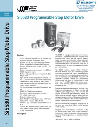
Si5580 Programmable Step Motor Drive
Features
• Si™, Si Command Language (SCL) or SiNet Hub pro-gramming
languages included with drive
• AC input 110V or 220V switch selectable, 50-60 Hz
• DC bus voltage 75 VDC full load, 80 VDC nominal
• Software selectable motor current from 0.5 – 5.5
amps/phase
• Software selectable motor resolution from 2,000 to
50,800 steps per revolution
• Software selectable idle current reduction 0, 25%,
50% or 100%
• Eight optically isolated programmable inputs 5 – 24
VDC. 2,200 ohms internal resistance. Can be config-ured
for sinking (NPN) or sourcing (PNP) signals.
• Three optically isolated programmable outputs 12 –
24 VDC, 100mA maximum
• One optically isolated output 5 VDC dedicated to fault
out
• RS-232 for PC/MMI communications
• Over current and over temperature protection
• 440 watts of usable power
• Screw terminal connectors
• Dual, MOSFET H-bridge, 3 state, pulse width modu-lated
amplifier switching at 20 – 30 KHz
• Ideal for 4, 6 or 8 leaded step motors NEMA sizes 23
& 34
• Optional Man Machine Interface (MMI) allows ma-chine
operator to enter specific motion parameters
• CE and TUV compliant
Description
The Si5580 is a programmable stepper drive/indexer
packaged in a rugged steel case painted black with white
epoxy silkscreen. Integral heat sink, mounting brackets,
switch covers and connectors are included with each
Si5580. The drive/indexer has been matched with twelve
recommended NEMA 23 & 34 motors and comes with all
operating software necessary to create a complete step-per
motion solution.
The Si5580 includes Applied Motion Products’,
Microsoft Windows based, Si™ software language for
quick set up and ease of use. The Si™ is ideal for stand-alone
operation. For more experienced users, with soft-ware
development expertise, the Si5580 also comes with
Applied’s Si Command Language (SCL) programming
instruction set. SCL allows for control of the Si™ drive
from a host PC or PLC thus permitting the user to per-form
a variety of motion, I/O tasks and system status re-trieval
via the host.
Multiple axis applications are handled by our SiNet™ Hub
Programmer, which gives you the ability to control up to 8
Si™ drives, either stepper or servo on the same hub. Not
only can you coordinate up to eight motors, the hub also
has access to the inputs and outputs of all the drives, pro-viding
your program with up to 64 inputs and 24 outputs.
You can also use Applied’s MMI which allows the machine
operator to enter specific motion commands.
Factory set to operate at 110-volt input; the Si5580 can be
set by the user to operate at 220-volt input by a simply
switch selection.
Pluggable screw terminal blocks are provided for the
I/O, motor and AC power inputs. Mating connectors,
programming cable with computer interface connector
as well as all operating software are provided with each
Si™ drive.
The Si5580 is both CE and TUV compliant.
2. STEPPER
SYSTEMS
59
Si5580 Technical Specifications
Sold & Serviced By:
POWER AMPLIFIER (MOTOR DRIVE):
AMPLIFIER TYPE .............................................. MOSFET, dual H-Bridge.
CURRENT CONTROL......................................... 3 state, pulse width modulated, switching at 20–30 KHz.
OUTPUT CURRENT ........................................... 0.5–5.5 amps, software selectable.
POWER SUPPLY ............................................... Linear, toroidal transformer based for high reliability and low noise. 110
or 220 VAC input, switch selectable. 50/60 Hz.
DC BUS VOLTAGE ............................................. DC voltage at nominal line voltage: 75 VDC full load, 90 VDC no load.
AC INPUT VOLTAGE .......................................... 110 or 220 VAC (switch selectable) 50/60 Hz.
MAXIMUM OUTPUT POWER ............................ 440 watts.
IDLE CURRENT REDUCTION ............................ 0%, 25%, 50%, or 100% software selectable.
MOTOR RESOLUTION....................................... 13 resolutions. Steps per revolution with 1.8° motor: 2000, 5000,
10000, 12800, 18000, 20000, 21600, 25000, 25400, 25600, 36000,
50000, 50800, software selectable.
STATUS LED'S .................................................. AC power (red)
Over Temperature (yellow)
Over Current (yellow)
CONTROLLER (INDEXER) SECTION:
SERIAL COMMUNICATION ............................... RS-232 programming port.
INPUTS ............................................................. 8 user programmable inputs. Can be used for triggering, sensing, hom-ing,
branching, jogging or limits, optically isolated 5-24 VDC.
OUTPUTS .......................................................... 3 general purpose, optically isolated 12–24 VDC outputs for interfacing
to other equipment. Open collector and emitter. 100 mA max.
PARAMETER RANGES ...................................... Distance: 1 to 16,000,000 steps. Speed: .025 to 50 revolutions per sec-ond
(in any microstep resolution). Acceleration: 1 to 3,000 rev/sec/sec.
Deceleration: 1 to 3,000 rev/sec/sec (set independently from accelera-tion).
Time Delays: 0.01 to 300 seconds. Output Pulse Widths: 2 to 500
milliseconds. Iterations per repeat loop: 1 to 65,535.
OPTIONAL OPERATOR INTERFACE (MMI) ....... NEMA 4/12 rated (splash proof & dust proof). 4 x 20 characters liquid
crystal display (LCD)standard or backlit. 20 key membrane keypad. Over-all
size: 4.9 x 4.9 x 1.42 inches.
SYSTEM SPECIFICATIONS:
OVERALL SIZE .................................................. 3.0 x 5.3 x 8.0 inches.
CHASSIS MATERIAL ......................................... Aluminum, black anodized with integral heat sink.
WEIGHT............................................................. 7.8 lbs.
AMBIENT TEMPERATURE ................................. 0° to 50°C (32° to 122°F).
HUMIDITY ......................................................... Maximum of 90% non-condensing.
CONNECTORS ................................................... Screw terminal connectors for input power and motor, and I/O signals.
MOTORS ........................................................... Can drive 4, 6 or 8 lead motors, NEMA sizes 11, 14, 17, 23 & 34.
CASE ................................................................. Steel with black paint and white epoxy silk screen. Includes switch covers.
AGENCY APPROVAL ......................................... CE & TUV.
ELECTROMATE
Toll Free Phone (877) SERVO98
Toll Free Fax (877) SERV099
www.electromate.com
sales@electromate.com
3. STEPPER
SYSTEMS
60
Si5580 Technical Specifications
MECHANICAL OUTLINE
BLOCK DIAGRAM
motor phase A motor phase B
3.00 "
1.25 "
POWER
TEMP
SHORT
PC/MMI LIMITS
8.00 " 8.97 "
110 or
220 VAC
INPUT1
INPUT2
INPUT3
INPUT4
CW JOG/IN5
CCW JOG/IN6
CW LIMIT
CCW LIMIT
to PC/MMI
FAULT OUT
OUT1
OUT2
eeprom
B–
B+
A–
A+
MOTOR
G
RS232 Optical
Fault OUT3
Monitor
overtemp LED
overcurrent LED
MOSFET
3 State
PWM
Power
Amplifier
fuse
Optical
Isolation
Isolation
Optical
Isoation
Si™
Microstepping
Indexer
Sequencer
Optical
Isolation
Internal
Power
Supply
3.07 "
9.25 "
5.45 "
5.30 "
2.02 "
0.25"
0.06"
2.15"
Si5580
Step Motor Driver
N
L
AC
POWER
STOP
IN 1
IN 2
IN 3
IN 4
JOG CW
JOG CCW
IN/JOG COM
IN/JOG COM
CW+
CW-CCW+
CCW-OUT
1+
OUT 1-
OUT 2+
OUT 2-
OUT 3+
OUT 3-
FAULT+
FAULT-
90V pk
Sold & Serviced By:
ELECTROMATE
Toll Free Phone (877) SERVO98
Toll Free Fax (877) SERV099
www.electromate.com
sales@electromate.com
4. STEPPER
SYSTEMS
61
Si5580 Connectors and Switches
I/O
position no.
1 in 1
2 in 2
3 in 3
4 in 4
5 jog cw
6 jog ccw
7 in/jog com
8 in /jog ccw
9 cw+
10 cw–
11 ccw+
12 ccw–
13 out 1+
14 out 1–
15 out 2+
16 out 2–
17 out 3+
18 out 3–
19 fault+
20 fault–
MOTOR
position no.
1 B–
2 B+
3 A–
4 B+
AC POWER
position no.
1 G
2 N
3 L
LIMITS
LEDs
power
overtemp
overcurrent
RS232 connector
pc
mmi
motor connector
AC power connector
input connector
input/limits connector
output connector
Sold & Serviced By:
ELECTROMATE
Toll Free Phone (877) SERVO98
Toll Free Fax (877) SERV099
www.electromate.com
sales@electromate.com
5. STEPPER
SYSTEMS
62
NEMA 23 Motor Data
Sold & Serviced By:
FEATURES RECOMMENDED MOTORS FOR Si5580
Motor P/N: 23122 23123 23124 23395 23398 23401
Motor Current amps 2.00 2.50 3.50 4.24 4.24 4.24
Resistance Ohms 1.24 1.18 0.82 0.32 0.38 0.50
Holding Torque oz-in 98 158 225 77 177 264
Rotor Inertia oz-in2 0.55 1.14 1.72 0.66 1.64 2.62
Bearings
Thrust Load (lbs) 25 25 25 25 25 25
Radial Load (lbs) 15 15 15 15 15 15
Radial Play inch/lbs .001 max .001 max .001 max .001 max .001 max .001 max
@ 1 lb @ 1 lb @ 1 lb @ 1 lb @ 1 lb @ 1 lb
End Play inch/lbs .001 max .001 max .001 max .003 max .003 max .003 max
@ 9 lbs @ 9 lbs @ 9 lbs @ 2.2 lbs @ 2.2 lbs @ 2.2 lbs
Weight lbs. 1.17 2.00 2.80 1.00 1.54 2.20
Motor current, resistance and torque ratings are with parallel connection
NEMA 23 Motor Dimensions
Model L
23122 2.00˝
23123 3.00˝
23124 4.00˝
Model L
23395 1.54˝
23398 2.13˝
23401 2.99˝
.75
L
.81 ± .03
.190
.060
18" min
2 x Ø.2500 +.0000
–.0005
Ø1.5 ± .002
2 X 1.856
2 X 2.22
4 X Ø.205 ± .01
MOUNTING
END
18.00 MIN
2 X 0.928
2 X 1.856
Ø1.50 ± 0.001
0.228 ± 0.006
FLAT
4 X Ø0.205 ± 0.01
2 X 2.22
+0.000
–0.001
.59± 0.01
L .197
.063 ± 0.008
.591 ± 0.01
Ø.250
.228 ±.006
FLAT
0.630 ± .039 .787 ± .020
2 X 1.11
MOUNTING
END
TYP
ELECTROMATE
Toll Free Phone (877) SERVO98
Toll Free Fax (877) SERV099
www.electromate.com
sales@electromate.com
7. STEPPER
SYSTEMS
64
NEMA 34 Motor Data
Sold & Serviced By:
FEATURES RECOMMENDED MOTORS FOR Si5580
Motor P/N: 34348 34349 34350 34474 34476 34478
Motor Current amps 4.84 7.07 8.34 6.35 6.35 5.64
Resistance Ohms 0.30 0.25 0.20 0.24 1.50 0.49
Holding Torque oz-in 212 424 636 389 861 1292
Rotor Inertia oz-in2 3.66 6.72 10.20 7.65 14.80 21.90
Bearings
Thrust Load (lbs) 50 50 50 35 35 35
Radial Load (lbs) 25 25 25 30 30 30
Radial Play inch/lbs .001 max .001 max .001 max .0008 max .0008 max .0008 max
@ 1 lb @ 1 lb @ 1 lb @ 1 lb @ 1 lb @ 1 lb
End Play inch/lbs .001 max .001 max .001 max .003 max .003 max .003 max
@ 15 lbs @ 15 lbs @ 15 lbs @ 1 lbs @ 1 lbs @ 1 lbs
Weight lbs. 3.00 5.40 7.70 3.86 6.18 8.66
Motor current, resistance and torque ratings are with parallel connection
NEMA 34 Motor Dimensions
Model L
34348 2.50˝
34349 3.70˝
34350 5.10˝
Model L
34474 2.60˝
34476 3.78˝
34478 4.96˝
18" min
2 X 3.26
MAX
Ø2.875
± .002
4 X Ø.216
± .01
2 X 2.74
L
1.19 ± .04
.19
.063
1.19 ± .03
Ø 3.38
MAX
Ø.3750
+.0000
–.0005
TYP
.2–.4
2 X 2.74±.01
MOTOR TO BE SUPPLIED
WITH 1/8 X .843 LG KEY
Ø.3750
.875
±.01
1.25
±.02
18
MIN
1.12±0.4
3.38±.02
L MAX
.330
.062
Ø.5000
+.0000
–.0005
.125
+.000
–.002
.555
+.000
–.017
4 X Ø.218 THRU
Ø2.875±.002
2 X 1.370
+.0000
–.0005
ELECTROMATE
Toll Free Phone (877) SERVO98
Toll Free Fax (877) SERV099
www.electromate.com
sales@electromate.com
9. STEPPER
SYSTEMS
66
DRIVE ONLY ORDERING
System Ordering Example: Si5580 - 23122
Drive Type Description
PDO 5580 Packaged 5.5 amps, 80 VDC, 110/220 VAC input.
Microstepping pulse & direction/oscillator drive.
Si5580 Packaged 5.5 amps, 80 VDC, 110/220 VAC input.
Sold & Serviced By:
Microstepping fully programmable drive/indexer with Si™ software.
Si5580 Ordering Information
COMPLETE SYSTEM ORDERING
Drive Type Motor System Number Step Motor Description
PDO 5580 23122 NEMA 23 one stack
Si5580 23123 NEMA 23 two stack
23124 NEMA 23 three stack
23395 NEMA 23 high torque one stack
23398 NEMA 23 high torque two stack
23401 NEMA 23 high torque three stack
34348 NEMA 34 one stack
34349 NEMA 34 two stack
34350 NEMA 34 three stack
34474 NEMA 34 high torque one stack
34476 NEMA 34 high torque two stack
34478 NEMA 34 high torque three stack
OPTIONAL ACCESSORIES
Type Description
MMI-01 Standard man-machine interface.
MMI-02 Man-machine interface with backlit display.
ELECTROMATE
Toll Free Phone (877) SERVO98
Toll Free Fax (877) SERV099
www.electromate.com
sales@electromate.com