Enhancing and Restoring Safety & Quality Cultures - Dave Litwiller - May 2024...
Fuel d13
1. DService Bulletin
Volvo Trucks North America
Greensboro, NC USA
Date Group No. Page
1.2007 230 254 1(12)
Trucks
Fuel System
Design and Function
D13F
Fuel System, Design and Function
W2005843
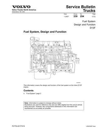
This information covers the design and function of the fuel system on the Volvo D13F
engine.
Contents
• “Fuel System” page 2
Note: Information is subject to change without notice.
Illustrations are used for reference only and can differ slightly from the actual vehicle
being serviced. However, key components addressed in this information are
represented as accurately as possible.
PV776-20177414 USA23087.ihval
2. DVolvo Trucks North America Date Group No. Page
Service Bulletin 1.2007 230 254 2(12)
Design and Function
Fuel System
When fault tracing, it is important to understand the function of the system in
order to avoid replacing non-defective components.
System Function
W2005892
3. DVolvo Trucks North America Date Group No. Page
Service Bulletin 1.2007 230 254 3(12)
Fuel is drawn up the fuel lines by the supply pump (1)
through the pickup tube in the fuel tank (2) in through the
Engine Electronic Control Unit (EECU) cooling coil (3),
and into the fuel filter housing (4). The fuel filter housing
is equipped with a pre-filter (5) and a water separator
(6), where fuel is filtered through the primary filter that
separates any water from the fuel.
The supply pump (1) forces the fuel into the fuel filter
housing through the main filter (7) to a cylinder head
longitudinal fuel gallery (8). This channel supplies each
unit injector (9) with pressurized fuel by a circular groove
around each unit injector in the cylinder head. The
overflow valve (10) controls the fuel supply pressure to
the unit injectors.
The return fuel from the overflow valve (10) is returned
back to the fuel filter housing and is mixed with the fuel
from the fuel tank in a channel within the fuel filter housing
(4).
Supply Pump Valves
Two valves are located in the supply pump (1).
The safety valve (11) allows fuel to flow back to the
suction side when the pressure becomes too high, e.g., if
the fuel filter is blocked or is too restricted. The non-return
valve (12) opens when hand-priming is used.
Automatic Bleeding
If air gets into the system, it is bled when the engine
starts. During bleeding, the air is pressed out through the
fuel filter housing over to the fuel tank through the return
line (25). Bleeding for the filter replacement is controlled
by valves (17) and (23).
Water Drainage
Draining water from the water separator (5) requires the
following:
• The sensor (14) in the water separator indicates water
in the fuel bowl.
• The engine is not running.
• The ignition key is in the ON position.
• The parking brake is applied.
When the switch (15) is depressed (located in the cab
instrument panel), the drain valve (16) opens for about
15 seconds and drains the water. If additional drainage
is needed, wait 6 minutes before repeating because the
function is on a timer.
Manual Hand Pump
The manual hand pump (11) is located on the fuel filter
housing and is used to pump fuel (when the engine is not
running) after the fuel system has been drained for repair,
etc. The non-return valve (22) for the hand-priming pump
is also located in the fuel filter housing.
4. DVolvo Trucks North America Date Group No. Page
Service Bulletin 1.2007 230 254 4(12)
Other
The fuel filter housing eliminates the need to drain the fuel
when replacing the filter. The valve pegs (17) and (21)
close when the fuel filter is removed. It is not necessary
to bleed the fuel system after replacing the filter, since
this is performed automatically when the engine is started
and runs for more than 2 minutes.
The plugged outlet (18) is fitted on the fuel filter housing.
The outlet is used when measuring supply pressure
after the fuel filter with an external pressure gauge. The
pressure sensor (19) on the fuel filter housing monitors
the supply pressure after the fuel filter. A fault code is
displayed on the instrument cluster if the fuel supply
pressure is less than the specified value.
A fuel heater (20) is available as an option. It is located
in the lower part of the water separator. The fuel tank
breather (24) prevents excessive vacuum in the fuel
tank(s) which could possibly result in fuel starvation.
Fuel System Components
W2004976
5. DVolvo Trucks North America Date Group No. Page
Service Bulletin 1.2007 230 254 5(12)
Current Volvo diesel engines are electronically controlled
and designed to meet today’s strict environmental
standards. Meeting these standards requires optimum
combustion. This demands, among other things, injecting
the exact amount of fuel into the combustion chamber
under very high pressure at precisely the correct time,
depending on engine speed, load, temperature and other
conditions.
Totally mechanical injection systems cannot meet these
demands and so requires that engines are equipped with
an electronically controlled injection system. An Engine
Electronic Control Unit (EECU) receives electrical signals
from the accelerator pedal and a number of other sensors
on the engine. These sensors provide speed, pressure
and temperature signals, sent to the EECU, which in turn
governs the fuel injection process. The EECU has a
built-in diagnostic system which electronically detects and
traces faults that might occur in the fuel system.
Each cylinder has four valves. Individual differences
always occur between the cylinders in an internal
combustion engine. The engine has a cylinder balancing
system, the purpose of which is to even out the amounts
of fuel between the cylinders. Cylinder balancing takes
place with the engine running at idle speed, providing
certain preconditions have been met.
6. DVolvo Trucks North America Date Group No. Page
Service Bulletin 1.2007 230 254 6(12)
Fuel Line Compression Fitting
Always replace the fuel line compression sealing
washers when:
• Troubleshooting for fuel aeration and/or
• Performing any service procedure that requires the
removal of engine fuel lines.
W2005829
Typical Compression Sealing Washers
7. DVolvo Trucks North America Date Group No. Page
Service Bulletin 1.2007 230 254 7(12)
Unit Injectors
W2005194
1. Pump Element 9. Needle
2. Pump Chamber 10. Nozzle
3. High Pressure Fuel
Line
11. Needle Control Valve
(NCV)
4. Return Spring 12. Needle Control Valve
Armature
5. Needle Backing
Chamber
13. Needle Control Valve
Electrical Coil
6. Needle Control Piston 14. Spill Valve Electrical
Coil
7. Needle Closing Spring 15. Spill Valve Armature
8. Needle Chamber 16. Spill Valve (SV)
8. DVolvo Trucks North America Date Group No. Page
Service Bulletin 1.2007 230 254 8(12)
Unit injectors for diesel engines have both injector pump
element and the nozzle assembly in the same body.
The pump stroke is activated by a camshaft lobe which
rotates at one half crankshaft speed in 4 stroke engines.
The pump stroke is always constant, but the delivery
through the injection nozzle is controlled by an electrically
operated solenoid valve, usually named a Spill Valve (SV).
The SV is located between the high pressure fuel line and
the low pressure fuel line. When the SV is closed, all the
fuel from the pump chamber is forced through the nozzle
and into the engine combustion chamber. When the SV
is open, the fuel is routed into the low pressure fuel feed
line and so no fuel passes through the nozzle. The SV is
operated by the Engine Electronic Control Unit (EECU)
by software and certain power stages capable of driving
the solenoids.
The injected fuel quantity per pump cycle is determined
by how long the SV is closed during the pump stroke. The
start of injection, i.e., injection timing, is determined by
when the SV is closed.
The injection pressure achieved is balanced out by a
number of factors:
1 The pumping capacity (pump element diameter, cam
rate) versus the restriction in the nozzle (the nozzle
hole area).
2 The engine speed, i.e., fuel/sec from the pump
chamber versus the nozzle hole area.
3 The nozzle opening pressure.
For a given unit injector/cam/nozzle specification, the
injection pressure is well defined over the speed/load
range for a specific engine. Engine exhaust emissions
are very dependent on the fuel spray characteristics and
are, to a large extent, influenced by the nozzle spray hold
design and the injection pressure. Therefore, it is of great
benefit to be able to change these parameters and today
it is possible to vary at least one of them, namely the
injection pressure. The method is to let the pressure build
up to a desired level before opening the nozzle needle.
9. DVolvo Trucks North America Date Group No. Page
Service Bulletin 1.2007 230 254 9(12)
To make the nozzle opening freely adjustable, a second
valve is used, the Needle Control Valve (NCV). The NCV
is a three port, two position valve, located between the
high pressure fuel line, the low pressure fuel line and a
needle backing chamber. The valve controls the pressure
in the backing chamber by either connecting the chamber
to the high pressure line or to the low pressure fuel line.
Pressure in the chamber exerts force on the back of the
nozzle by the control piston. The diameter of the control
piston is the same as the needle guide diameter so that
when the needle is off the needle seat, pressure balance
is achieved. When the needle is on the needle seat, the
effective area on the lift side is reduced and, with the
same pressure acting on both sides, there is a net force
keeping the needle on the needle seat.
The force equation is:
• Pressure x control piston area plus spring force acts to
keep the needle closed.
• Pressure x lift area acts to open the needle.
With the same pressure acting on both areas, the acting
force is spring force plus the pressure force due to the
difference of the two effective areas. This keeps the
needle closed.
When the desired pressure in the needle chamber is
achieved, the NCV is activated, closing the high pressure
line to the back of the needle control piston and at the
same time, connecting the back of the piston to the low
pressure line. The high pressure on the back of the
needle control piston is removed and the pressure on the
lift side now overcomes the closing force from the needle
closing spring and the needle opens.
In this way, the Needle Opening Pressure (NOP) can be
varied between the preset spring NOP and the maximum
pumping pressure. Practically, the levels used are
between 250–1800 bar, to be compared with a common
nozzle, using 250–350 bar opening pressure.
The influence on spray formation is such that the soot
(particulate matter) formation is lowered with increased
needle opening pressure while at the same time, NOx
formation is increased.
By using a variable NOP over the speed/load range of the
engine, it is possible to balance with trade-off between the
particulate matter and NOx formation to achieve the best
combination for each speed/load point and thus decrease
engine exhaust emissions.
10. DVolvo Trucks North America Date Group No. Page
Service Bulletin 1.2007 230 254 10(12)
Injector Operational Phases
Fill Phase
During the filling phase, the pump plunger is on its way
up, the camshaft lobe is passing its highest point and the
rocker arm is on its way toward the camshaft base circle.
The fuel valve is open, allowing fuel to flow into the unit
injector from the lower fuel gallery. Fuel flows into the
cylinder head and the unit injector pump cylinder. Filling
continues until the pump plunger reaches its upper
position.
Spill Phase
The spill phase begins when the camshaft lobe forces the
rocker arm to push the pump plunger down.
The fuel can now flow through the fuel valve, through the
holes in the unit injector and out through the fuel gallery.
The spill phase continues as long as the fuel valve is
open.
Injection Phase
The injection phase begins when the fuel valve closes.
The camshaft lobe and rocker arm continue to press
down on the pump plunger and injection occurs as the
path through the fuel valve closes. The injection phase
continues as long as the fuel valve is closed.
Pressure Drop Phase
The injection phase ends when the fuel valve opens
and pressure in the unit injector drops below the nozzle
opening pressure. The fuel flows through the open fuel
valve, through the unit injector holes and out through the
fuel gallery. Note that the fuel valve position (closed or
open) determines when the injection phase begins and
ends. The time during which the fuel valve is closed
determines the amount of fuel injected at each pump
stroke.
11. DVolvo Trucks North America Date Group No. Page
Service Bulletin 1.2007 230 254 11(12)
Fuel Filter
W2005849
The system is equipped with a large fuel filter located on
the left-hand side of the engine. The filter insert consists
of a corrugated filter paper with a high resistance to
water and very good filtering properties. In addition, a
fine-gauge net filter on the fuel suction line in the fuel tank
separates any possible solid impurities before the fuel is
pumped up into the system.
Fuel Feed Pump
The capacity of the pump has been adapted to give the
correct pressure and flow to the unit injectors. Filling the
unit injectors requires relatively high pressure. The flow
must be large enough to even out any fuel temperature
differences in the cylinder head fuel gallery.
12. DVolvo Trucks North America Date Group No. Page
Service Bulletin 1.2007 230 254 12(12)
Engine Electronic Control Unit (EECU)
W2003778
The engine electronic control unit is the central part of the
injection system. It is located on the left-hand side of the
engine. The EECU receives continuous information from
the accelerator pedal and from several other sensors on
the engine. It calculates the amount and the time to inject
fuel into the cylinders. Electrical wiring to the unit injectors
transmits control signals to the injectors from the EECU.
The EECU uses the flywheel sensor to monitor engine
rotation and engine speed variations during a revolution.
This allows the EECU to ensure that each unit injector
receives exactly the correct amount of fuel. The EECU
stores information when a fault occurs or if something in
the system is abnormal. Intermittent faults are also stored
and can be traced at a later time.