SlideShare ist ein Scribd-Unternehmen logo
1 von 59
Downloaden Sie, um offline zu lesen
1
CHAPTER 1
1.1 Introduction
1.1.1 .Definition
GEAR BOX
A Gearbox is a device that used for transmitting power from the Power source to
the output shaft. A gearbox has a set of gears that are enclosed in a casing. The gears are
mounted on shafts which rotate freely about their axis
Figure 1 gear box
Spur gears are used to transmit power and rotary motion between parallel shafts. If teeth of the
gear wheels are parallel to the axis of wheel, the gears are called spur gears. It is used when axes
of the driving and driven shafts are parallel and co-planar. The smaller of the two gears in mesh
is called the pinion, and the larger is designated as the gear.
`
2
Reduction gear box consists of 2 gears having same no. Of teeth but different diameters. The
number of teeth is proportional to the circumference of the gear; the smaller circumference gear
will have fewer teeth than the larger one. The smaller gear makes two revolutions for every one
revolution of large gear. The amount of torque obtained at larger gear is twice comparing to the
torque available in smaller gear. The speed of the output gear is decreases and the torque is
increasing proportionally
Function of gear box
 In the most basic sense, a gear box function like any system of gears.it alters torque and
speed between a driving device like a motor and a load. The gearbox is a mechanical
method of transferring energy from one device to another and is used to increase torque
while reducing speed. See in gear box design as we increase speed we decrease the torque
this mean speed and torque have inverse relationship in this case.
In general gear has three main functions in gear box or in any system
 To control speed at the same time to control torque
 To change the direction of motion
 To transfer power
1.1.2 Principle of operation
The gears and shafts present in the reduction gearbox undergo various forces acting over them.
The two stage reduction gearbox consists of three shafts and four gears (two driver gears, two
driven gears). The driver gear of the first stage of reduction which is probably the smallest gear
in the entire reduction gear box is present on the input shaft which gets the input And the second
`
3
shaft also called as the intermediate shaft consists of the driven gear of the first stage of
reduction a`nd also the driver gear of the second stage of reduction which are termed to be as
compound gears. Finally, the third shaft called as the output shaft consists of the driven gear of
the second stage of reduction which could be the largest gear
1.1.3 Application
Application of bevel gear and spur gear
 Automobile deferential (bevel gear)
 Material handling equipment (bevel gear)
 Food canning equipment (bevel gear)
 Food packaging equipment (bevel gear)
 Clock and watches(for spur gear)
 Washing machine (for spur gear)
 Gear pumps(for spur gear)
 Motorcycle gear box(for spur gear)
Bevel gear Used to transmit the power and motion between two intersecting shaft by the
changing profile we can transmit power and motion two shafts which are not exactly
`
4
1.1.4 Advantage and disadvantage
Advantage of bevel gear and spur gear
 It can operate under high speed and high load (bevel gear)
 Its suitable for 1:1 velocity ratio at an angel (bevel gear)
 It has simple in construction(for spur gear)
 It has easy to manufacture(for spur gear)
 It has low cost(for spur gear)
 It has excellent precision rating (for spur gear)
Disadvantage of bevel gear and spur gear
 It‟s complicated in design and manufacturing(bevel gear)
 It requires more precision(bevel gear)
 Center distance is limited (for spur gear)
 Noise at high speed(for spur gear)
 Large amount of stress (for spur gear)
`
5
1.2 Background
1.2.1 Definition
GEARS
A Gear is a rotating machine part having cut teeth, which mesh with another
toothed part to transmit torque. Geared devices can change the speed, torque, and
direction of a power source. Gears almost always produce a change in torque, creating
a mechanical advantage, through their ratio. The teeth on the two meshing gears all have
the same shape. Two or more meshing gears, working in a sequence, are called a gear
train or a transmission.
1.2.2 Historical development of gear
Gears were a logical continuation of the invention of the wheel. That gears are called the biggest
invention after the wheel is not unthinkable. In any case, we can‟t live a normal day in our lives
without gears: without gears no production, no energy and no transport. The use of gears is so
obvious that we never dwell on where they come from. In this article, out of respect for the gear,
we will detail the interesting history.
Until now, the Greeks were given the honor of the invention of the wheel. Estimated that they
were first used 300 years BC in Alexandria for the first time this mechanism.
From unofficial writings show that in China already 800 v.C. differentials (a system of gears)
were made. The first gears were made of wood, with wooden rods and teeth. Worn teeth could
thus be replaced separately.
`
6
By the year 100 v.C. the Greeks used metal gears with cylindrical teeth in complex computing
equipment and astronomical calendars. We know this by the discovery of the Antikythera
Mechanism (see picture), the oldest known gear machine. This around 100 v.C. produced
mechanism was found in 1900 in a wreck off the coast of the Greek island of Antikythera. The
mechanism contains more than 30 gears for complicated astronomical calculations of time. Was
this actually the first computer/ in later centuries, the gear was one of the most important parts of
modern technology, incorporated into almost all the mechanisms, machines and vehicles. [ ]
1.2.3 Components of a gearbox
A Gearbox comprises of major components namely
 Casing
 Gears
 Shafts
 Bearings
`
7
Casing
Casing is a fixture that fixes all the shafts and assembles all gears into an assembly without any
interference. Casing also contains the mounting points to mount it in a powertrain Assembly. The
Casing takes the load imposed by the power source. Vibrations are also transmitted in case the
power source is an Engine over the years; Cast Iron is being used for manufacturing casing.
Nowadays, casings are coming in Steels or oven Aluminum Alloys.
Gears
Gears are mechanical components that have the ability to transmit motion from one shaft to
another. The transmission of motion might not be uniform, and it can include changes indirection
and torque. More specifically, gears can be described as toothed wheels which typically are
round (but not necessarily) [1]. Gears have evolved from rolling cylinders, to wooden wheels
with pegs, to the common gears used today which have specially shaped teeth that are shaped or
cut into metal wheels.
Shafts
A shaft is a rotating machine element which is used to transmit power from one place to
another. The power is delivered to the shaft by some tangential force and the resultant
torque (or twisting moment) set up within the shaft permits the power to be transferred to
various machines linked up to the shaft. In order to transfer the power from one shaft to
another, the various members such as pulleys, gears etc., are mounted on it.
Bearings
`
8
Bearing is a component that ensures smooth rotation between the fixed support
and the rotating shafts. These components are made of high carbon alloy steels that can
bear huge amount of loads and rotate at high RPMs/There are two types of bearing---
Sliding contact bearing and rolling contact bearings. Sliding contact have a fluid between
the inner and outer race that ensures smooth rotation. Rolling contact bearings also
known as ball bearings have a handful of tiny hardened steel balls or rollers between the
inner and outer race, these balls are super finished and have less friction compared to the
sliding contact bearings.
1.2.4 Classification of gears
Figure 2 classification of gears
1.2.5 Types of Gears
Spur gears, spur gears are used to transmit rotary motion between parallel shafts. They are
cylindrical, and the teeth are straight and parallel to the axis of rotation and also they are used to
transmit motion from one shaft to another the most common gears are spur gears and are used in
`
9
series for large gear reductions. Spur gears are used in washing machines, screwdrivers, windup
alarm clocks, and other devices.
Helical gears, helical gears are used to transmit motion between parallel or nonparallel shafts.
Helical gears operate more smoothly and quietly compared to spur gears due to the way the teeth
interact. The teeth on a helical gear cut at an angle to the face of the gear. The typical range of
the helix angle is about 15 to 30 deg.
Bevel gears, Bevel gears are used to transmit rotary motion between intersecting shafts. The
tooth of the bevel gears can be cut straight or spiral. Have teeth formed on conical surfaces and
are used mostly for transmitting motion between intersecting shafts. The figure actually
illustrates straight-tooth bevel gears. Spiral bevel gears are cut so the tooth is no longer straight,
but forms a circular arc. Hypoid gears are quite similar to spiral bevel gears except that the shafts
are offset and nonintersecting.
Worm gears, Worm gear sets are used to transmit rotary motion between nonparallel and
nonintersecting shafts consist of a worm and a worm wheel.. Worm gear drives are used for
shafts, the axes of which do not intersect and are perpendicular to each other. Worm gear drives
are characterized by high speed reduction ratio. The direction of rotation of the worm gear, also
called the worm wheel, depends upon the direction of rotation of the worm and upon whether the
worm teeth are cut right-hand or left-hand. Worm gear sets are also made so that the teeth of one
or both wrap partly around the other. Such sets are called single enveloping and double-
enveloping worm gear sets. Worm gear sets are mostly used when the speed ratios of the two
shafts are quite high, say, 3 or more.
`
10
1.2.6 Working principles of various types
1.3 Objective
1.3.1 General objective
The general objective of this project is to design Gear Box with the details drawing
1.3.2 Specific objective
Design and considering the following part
Parts to be designed
 To designed the component of gear box
 To designed the part of gear box
 To designed the part drawing of gear box
 To designed the assembly of gear box
1.4 Scope
The scopes are: Detail design a gear reducer at the following design specification my gear box
type give from teacher is Intersecting fist stage bevel and second spur gear type the stage will be
two stage, the rated power 4.8hp and input speed 1650rpm, usually low shock level, occasional
shock Literature review on speed reducer gearbox and gear Design speed reducer gearbox using
detail drawing
`
11
MATERIAL SELECTION
RECOMMENDATION
LITERATURE REVIEW
RESULT & DISCUSSION
SYNTHESIZE
DESIGN ANALYSIS
NEED OR AIM
CONCLUSION
DETAIL DRAWING
1.5 Methodology
This project has 4 chapters. And we can classify them in to two major parts. The first part is an
introductory part and the second part is literature review part and other part will be analysis of
the project by using the force analysis, geometrical analysis as well as the detail drawing. Finally
this project design is focus on the gear box design which is different parameters such as force;
stresses etc. are calculated by numerical method. Generally describe by using block diagram of
methodology as follow
`
12
1.6 Limitation
In the design of Gear box we have faced so many limitations including:
 Lack of resource i.e. computer access, Mat lab, and other software‟
 Lack of comfortable area by means of political problem in the university.
`
13
CHAPTER 2
2.1 Literature Review
For design of a gear box, it is necessary to look into the design aspects and literature available in
order to better understand the designing aspects
Prof. K.Gopinath & Prof. M.M.Mayuram in which he conclude that History of gears, Definition
of gears, Types of gears and their applications. Spur Gear and Helical Gear provide by using pdf.
Prof. A. V. Patil Faculty Department of Mechanical Engineering S.S.G.B.C.O.E India work on
“Stress and Design Analysis of Triple Reduction Gearbox Casing” This work focuses on the
stress analysis of triple reduction of gearbox casing designed and manufactured by steward
Ramesh Banothu worked on „Design and analysis of Gear Shaft‟ in which he concluded that
Vibrations can be transmitted from the casing to the gears through the gear shafts. He even
conclude that the shafts are subjected to bending moments and slight torsion when there are at
least two gears mounted on one shaft.
Vilas Warudkar from his study „Design and Optimization of 2-Stage Reduction Gearbox‟ has
concluded the methodology to make a conventional Reduction gearbox for Water pumps. This
Gearbox did not use any alloys for materials and did not consider vibrations or Thermal analysis
inside the Gearbox.
Ralph E.Taggert made a detailed experimental study on „Forces that affect the operation and
efficiency of reduction Gearbox‟ that contributes the complete information about a single stage
reduction gearbox
`
14
Machine Company These gearboxes are designed for high torque and low speed applications for
operating movable bridges, heavy hoisting machinery, or other lifting mechanisms.
Chandresh Motka Assistant Professor Department of Mechanical Engineering Kalol Institute of
Technology and Research Center, Kalol “Analysis & Optimization of Gearbox Efficiency- A
Review” focus on The less efficiency of gear box of a machine tool is a serious problem as it
increases maintenance cost and also affects the reputation of a firm. Hence its life has to be
increased and should be made more reliable.
The Volvo Group [1] introduced a concept of Automatic Transmissions. It is discussed that
Manual Gearboxes are complicated in design and is difficult for the users to drive the vehicle.
Usage of so many components in the manual gearbox also reduced the efficiency and the clutch
plates had to be replaced periodically. The company stated that it is difficult to implement
manual gearbox in smaller vehicles
`
15
CHAPTER 3
3.1 Material selection
The first step in the gearbox design process is to select the material. A material is to be selected
by doing intensive research on the properties of the various materials.
Shaft material
A shaft is a rotating machine element which is used to transmit power from one place to another.
The power is delivered to the shaft by some tangential force and the resultant torque (or twisting
moment) set up within the shaft permits the power to be transferred to various machines linked
up to the shaft. In other words, we may say that a shaft is used for the transmission of torque and
bending moment. The various members are mounted on the shaft by means of keys or splines.
Material Used for Shafts the material used for shafts should have the following properties:
 It should have high strength.
 It should have good machinability.
 It should have low notch sensitivity factor.
 It should have good heat treatment properties.
 It should have high wear resistant properties.
The material used for ordinary shafts is carbon steel of grades 40 C 8, 45 C 8, 50 C 4 and 50
C12. The mechanical properties of these grades of carbon steel are given in the following table
`
16
Table 1 Mechanical properties of steels used for shafts Table 14.1[ ]
When a shaft of high strength is required, then an alloy steel such as nickel, nickel-chromium or
chrome-vanadium steel is used 45C8 carbon steel is selected as shaft material due to its better
mechanical properties
Material for Gears
For choosing the material and designing the gears, the following data should be given: In the
design of a gear drive, the following data is usually given:
 The power to be transmitted.
 The speed of the driving gear,
 The speed of the driven gear or the velocity ratio, and
 The center distance.
The following requirements must be met in the design of a gear drive:
 The gear teeth should have sufficient strength so that they will not fail under static
loading or dynamic loading during normal running conditions.
 The gear teeth should have wear characteristics so that their life is satisfactory.
 The use of space and material should be economical.
 The lubrication of the gears must be satisfactory.
`
17
For the pinion
For the pinion selected material the cast iron is obtained by re-melting pig iron with coke and
limestone in a furnace known as cupola. It is primarily an alloy of iron and carbon. The carbon
contents in cast iron vary from 1.7 per cent to 4.5 per cent. It also contains small amounts of
silicon, manganese, phosphorous
Since the cast iron is a brittle material, therefore, it cannot be used in those parts of machines
which are subjected to shocks. The properties of cast iron which make it a valuable material for
engineering purposes are its low cost, good casting characteristics, high compressive strength,
wear resistance and excellent machinability. The compressive strength of cast iron is much
greater than the tensile strength. Following are the values of ultimate strength of cast iron
 Tensile strength = ( )
 Compressive strength = ( )
 Shear strength = ( )
Cast iron has a various types i selected grey cast iron it has a low tensile strength, high
compressive strength and no ductility. It can be easily machined. A very good property of grey
cast iron is that the free graphite in its structure acts as a lubricant. Due to this reason, it is very
suitable for those parts where sliding action is desired.
Table 2 grey cast iron table 2.8(6)
`
18
For the gear
For the gear selected material for the same as shaft The material used for ordinary gear is carbon
steel of grades 40 C 8, 45 C 8, 50 C 4 and 50 C12. The mechanical properties of these grades of
carbon steel are given in the above table1.
When a shaft of high strength is required, then an alloy steel such as nickel, nickel-chromium or
chrome-vanadium steel is used 45C8 carbon steel is selected as shaft material due to its better
mechanical properties
Casting Design
An engineer must know how to design the castings so that they can effectively and efficiently
render the desired service and can be produced easily and economically. In order to design a
casting, the following factors must be taken into consideration …page 56[ ]
 The function to be performed by the casting,
 Soundness of the casting,
 Strength of the casting,
 Ease in its production,
 Consideration for safety, and
 Economy in production
In rolling contact bearings, the contact between the bearing surfaces is rolling instead of sliding
as in sliding contact bearings
`
19
Advantage of bearing
 Low starting and running friction except at very high speeds.
 Accuracy of shaft alignment.
 Low cost of maintenance, as no lubrication is required while in service.
 Small overall dimensions.
 Easy to mount and erect.
 Cleanliness.
The rolling contact bearings, depending upon the load to be carried, are classified as : (a) Radial
bearings, and (b) Thrust bearings
When a split bearing is used, the bearing cap is tightened on the top. The load is usually carried
by the bearing and not the cap, but in some cases e.g. split connecting rod ends in double acting
steam engines, a considerable load comes on the cap of the bearing. Therefore, the cap and the
holding down bolts must be designed for full load
`
20
CHAPTER 4
4.1 Design Analysis
4.4.1 Design of first stage (bevel gear)
For satisfactory operation of the bevel gears, the face width should be from 6.3 m to 9.5 m, where
m is the module. Also the ratio L / b should not exceed 3. For this, the number of teeth in the
pinion must not less than 48.
For the analysis we have to assume that teeth of pinion
And the velocity ratio V.R=2
Now
Pitch angle for the pinion
, ( ) ( )
Pitch angle for the gear,
`
21
We know that the equivalent (or formative) number of teeth,
Lewis factor 𝑌 = 𝜋 ∗ 𝑦 where
Tooth form factor (or Lewis factor) for pinion
𝑌 ( )
Tooth form factor (or Lewis factor) for Gear
𝑌 ( )
Since the allowable static stress ( ) for both the pinion and gear is same (i.e. 140 MPa or
N/mm2
) and 𝑌 is less than𝑌 , therefore the pinion is weaker. Thus the design should be based
upon the pinion.
Torque on the pinion
𝜋
Where,
s
`
22
𝜋
Tangential load on the pinion
∗
∗
We know that pitch line
𝜋 ∗ ∗ 𝜋 ∗ ∗ 𝜋 ∗ ∗ 𝜋 ∗ ∗
Allowable working stress


We know that length of the pitch cone element or slant height element or slant height
∗ ∗
Since the face width (b) is 1/4th of the slant height of the pitch one .should not exceed 1/3th
So let say 1/4th
We know that tangential load on the pinion
𝜋 ∗ 𝑌 ( )
( ) 𝜋 ∗ 𝑌 ( )
`
23
( ) 𝜋 ∗ ( )
Solving this expression by hit and trial method, we find that
Now
The proportions for the bevel gears may be taken as follows
∗ ∗
`
24
∗ ∗
4.4.2 Design of a Shaft for Bevel Gears
 Let assume that pressure angle of teeth is ° ,the pair of bevel gears connect two shaft
at right angle and overhang =150mm[ ]
Cone lengths L
√ √
In designing a pinion shaft, the following procedure may be adopted
1. First of all, find the torque acting on the pinion. It is given by
∗ ∗
∗ ∗
2. Find the tangential force (WT) acting at the mean radius ( ) of the pinion. We know that
But
( )
`
25
( )
∗
3. Now find the axial and radial forces (i.e. WRH and WRV) acting on the pinion shaft as
Discussed below.
Now the radial force (WR) acting at the mean radius may be further resolved into two
components, WRH and WRV, in the axial and radial directions as shown in Fig. .
Figure 3 Forces acting on a bevel gear
A little consideration will show that the axial force on the pinion shaft is equal to the radial force
On the gear shaft but their directions are opposite. Similarly, the radial force on the pinion shaft
is equal to the axial force on the gear shaft, but act in opposite directions.
`
26
There are three loads acting on bevel gear which are tangential force, axial and radial forces.
The force relationships are
The commonly used pressure angle for bevel gears is 14.5°, although pressure angles of 22.5°
and 25° are used for heavy-duty drives.
Therefore the axial force acting on the pinion shaft,
∗
∗
And the radial force acting on the pinion shaft
∗
∗
4. Find resultant bending moment on the pinion shaft as follows :The bending moment due
to and is given by
`
27
W
75mm
150mm
We know that the torque transmitted by the shaft
∗ ∗
And we know that ∗ ∗
∴ Tangential force on the pinion
∗
And the normal load acting on the tooth of the pinion
Since the pinion is mounted at the end of the shaft, therefore maximum bending moment at the
end of the pinion
`
28
First of all, considering the vertical loading at W. Let and be the reactions at the
bearings A and B respectively. We know that
Taking moments about A,
∗ ∗
∗ ∗
Taking moments about B,
∗ ∗
∗ ∗
The summation of vertical loading is
Now considering horizontal loading at W. Let and be the reactions at the bearings A
and B respectively. We know that there is no applied force in horizontally then the
summation of horizontal force is zero
∴Resultant bending moment
√
`
29
√
5. Since the shaft is subjected to twisting moment (T ) and resultant bending moment
(M),therefore equivalent twisting moment
√
√
6. Now the diameter of the pinion shaft may be obtained by using the torsion equation. We
know that
𝜋
∗ ∗
√
∗
𝜋 ∗
Where = Diameter of the pinion shaft,
 = Shear stress for the material of the pinion shaft
7. Now the diameter of the gear shaft may be obtained by using the torsion equation. We
know that
𝜋
∗ ∗
√
∗
𝜋 ∗
Where = Diameter of the gear shaft,
`
30
4.4.3 Design of intermediate shaft
A 50mm C D 50mm B
200mm
We know that the torque transmitted by the shaft
∗ ∗
And we know that ∗ ∗
∗ ∗
∴ Tangential force on the Gear
∗
Assuming that the torque at C and D is same (i.e. 40836 N-mm), therefore tangential force on
the gear C, acting downward
∴ Tangential force on the Pinion
G
E
A
R
Pi
ni
o
`
31
∗
Since the pinion is mounted at the right side of the shaft and the gear is mounted at the left side
of the shaft therefore maximum bending moment at the both gear
Now let us find the maximum bending moment for vertical and horizontal loading
50mm 200mm 50mm
First of all, considering the vertical loading at W. Let and be the reactions at the
bearings A and B respectively. We know that
Taking moments about A,
𝑁
𝑁
𝑁
`
32
∗ ∗ ∗
∗
Taking moments about B,
∗ ∗ ∗
∗
The summation of vertical loading is
Now considering horizontal loading at W. Let and be the reactions at the bearings A
and B respectively. We know that there is no applied force in horizontally then the
summation of horizontal force is zero
We know that Shear force.
`
33
Now let us find the maximum bending moment for vertical and horizontal loading. First of all,
considering the vertical loading at C. Let RAV and RBV be the reactions at the bearings A and B
respectively. We know that
RAV + RBV = 680N
Taking moments about A, we get
RBV × 200 = 680 × 150
RBV = 680 × 150 / 200 = 510N
RAV = 680 – 510 = 170 N
We know that B.M. at A and B,
MAV = MBV = 0
B.M. at D, MDV = RAV × 50 = 170 × 50 = 8500N-mm
B.M. at C, MCV = RBV × 100 = 510 × 50 = 25500 N-mm
Now considering horizontal loading at D. Let RAH and RBH be the reactions at the bearings A and
B respectively. We know that
RAH + RBH = 425N
Taking moments about A, we get
RBH × 200 = 50*425 = 425 × 50/ 200 = 106.25N
RAH = 425– 106.25 = 318.75 N
`
34
We know that B.M. at A and B,
MAH = MBH = 0
B.M. at D, MDH = RAH × 50 = 318.75 × 50 = 15937.5 N-mm
B.M. at C, MDH = RBH × 50 = 106.25 × 50 = 5312.5 N-mm
We know that resultant B.M. at C,
√
√
And resultant B.M. at C,
√
√
We see that the bending moment is maximum at C.
∴Resultant maximum bending moment
Since the shaft is subjected to twisting moment (T ) and resultant bending moment (M),therefore
equivalent twisting moment
√
√
`
35
1. Now the diameter of the pinion shaft may be obtained by using the torsion equation. We
know that
𝜋
∗ ∗
√
∗
𝜋 ∗
Where = Diameter of the pinion shaft,
 = Shear stress for the material of the pinion shaft
2. Now the diameter of the gear shaft may be obtained by using the torsion equation. We
know that
𝜋
∗ ∗
√
∗
𝜋 ∗
Where = Diameter of the gear shaft,
4.4.4 Key Design Calculation
A key is a piece of mild steel inserted between the shaft and hub or boss of the pulley to connect
these together in order to prevent relative motion between them. It is always inserted parallel to
the axis of the shaft. Keys are used as temporary fastenings and are subjected to considerable
crushing and shearing stresses. A keyway is a slot or recess in a shaft and hub of the pulley to
accommodate a key. There are different types of key but I well select key is rectangular sunk key
`
36
Figure 4 rectangular key
The sunken keys are provided half in the keyway of the shaft and half in the keyway of the hub
or boss of the pulley.
Width of key, w = d / 4; and thickness of key, t = 2w / 3 = d / 6
Where d = Diameter of the shaft or diameter of the hole in the hub
 The rectangular key is designed as discussed below:
Table 3 Proportions of standard parallel, tapered and gibe head keys. From Table 13.1,[ ]
4.4.5 Design of a key for first stage (Bevel Gears)
`
37
Where
D= = 22mm
Now from the table we gave the width and thickens of key (i.e., 3mm and 3mm respectively)
We know that shear stress τ=42MPa
Crushing stress
The length of key is obtained by considering the key in shearing and crushing. Let l = Length of
key. Considering shearing of the key. For gear
We know torsional shearing strength (or torque transmitted) of the shaft
……………………..( )
And we know that shearing strength (or torque transmitted) of the key,
……………………( )
From equations (i) and (ii), we have
Now considering crushing of the key. We know that shearing strength (or torque transmitted) of
the key,
………………( )
From equations (ii) and (iii), we have
Taking larger of the two values, we have length of key,
`
38
4.4.6 Design of second stage (spur gear)
From the first we have power transmitted of 3528watts and the output speed of the first stage is
input speed of the second stage and the second stage of gear ratio is 3:1
And also the pressure angel is 20°
The number of teeth on the pinion (TP) in order to avoid interference may be obtained from the
Following relation:
∗
[√ ( ) ]
Where =1module
G=Gear ratio
=Pressure angle or angle of obliquity
∗
[√ ( ) ]
∗ ∗
The following table shows the values of service factor for different types of loads
`
39
Table 4 Values of service factor Table 28.10[6]
So assume that the reduction transition gear works 10houre per day the value of service factor
became 1.54
In order to design spur gear the following producer may be followed
 First of all to design tangential tooth load is obtain from the power transmitted and the
pitch live velocity by using the following relation
∗
Where Permissible tangential tooth load in newton,
P = Power transmitted in watts,
*v = Pitch line velocity in m / s,
D = Pitch circle diameter in meters
𝜋 ∗ ∗ ∗ 𝜋 ∗ ∗ ∗
∗ ∗
`
40
 Apply the Lewis equation as follows
𝑦
But
∗
And we have
Now Apply the Lewis equation
∗ 𝜋 𝑦
∗ 𝜋 𝑦
The face width (b) may be taken as 3 pc to 4 pc (or 9.5 m to 12.5 m) for cut teeth and 2 pc to 3 pc
(Or 6.5 m to 9.5 m) for cast teeth for 3pc =3*m*
Tooth from factory y for 20°
𝑌
𝑌
Then
∗ 𝜋
`
41
Solving this expression by hit and trial method, we find that
Now
pc =3*m* * mm
∗
 Calculate the dynamic load (WD) on the tooth by using Buckingham equation, i.e.
∗ ∗ ( )
∗ √
In calculating the dynamic load (WD), the value of tangential load (WT) may be calculated by
Neglecting the service factor (CS) i.e.
`
42
The value of deformation factor given below table
Table 5 Values of deformation factor (C ). Table 28.5.[6]
Before that we need have yon know the value of tooth error(e) in action also the value
taken from the table
`
43
Table 6 Values of tooth error in action (e) verses module Table 28.7(6)
From the above table we get the value of deformation factors C=770Nmm and tooth error
in action e=0.0700mm
Now
∗ ∗ ( )
∗ √
∗ ∗ ( ∗ )
∗ √ ∗
Find the static tooth load (i.e. beam strength or the endurance strength of the tooth) by using
The relation, ∗ ∗ ∗ 𝑦 ∗ ∗ 𝜋 ∗ 𝑦
For safety against breakage, WS should be greater than WD.
`
44
From the table below we have the value of surface endurance limit
Table 7 Values of surface endurance limit Table 28.9.[6]
Let take the value 320mpa
∗ ∗ ∗ 𝑦 ∗ ∗ 𝜋 ∗ 𝑦
∗ ∗ ∗ 𝑦 ∗ ∗ 𝜋 ∗
 Finally, find the wear tooth load by using the relation
By using this formula
∗ ∗ ∗
Where
=wear tooth gear
`
45
=diameter of the pinion
b=face width
=ratio factor ∗ ∗
= Load-stress factor (also known as material combination factor) in N/mm2.
=
( )
( )
=
( )
( )
Then
∗ ∗ ∗
∗ ∗ ∗
4.4.7 Design of Shaft for Spur Gears
In order to find the diameter of shaft for spur gears, the following procedure may be followed
50mm
200mm
`
46
We know that the torque transmitted by the shaft
∗ ∗
And we know that ∗ ∗
∴ Tangential force on the pinion
∗
 First of all, find the normal load (WN), acting between the tooth surfaces. It is given by
Where WT = Tangential load, and
= Pressure angle.=20°
A thrust parallel and equal to WN will act at the gear center as shown in Fig. 5.
Figure 5 Load acting on the gear
 The weight of the gear is given by
`
47
∗ ∗
Where
TG = No. of teeth on the gear,
b = Face width in mm, and
m = Module in mm
∗ ∗
∗ ∗ ∗
 Now the resultant load acting on the gear
√ ∗
√ ∗ ∗
If the gear is overhung on the shaft, then bending moment on the shaft due to the resultant
Since the gear is mounted at the end of the shaft, therefore maximum bending moment at the end
of the gear
First of all, considering the vertical loading at W. Let and be the reactions at the
bearings A and B respectively. We know that
Taking moments about A,
`
48
∗ ∗
Taking moments about B,
∗ ∗
∗ ∗
The summation of vertical loading is
Now considering horizontal loading at W. Let and be the reactions at the bearings A
and B respectively. We know that there is no applied force in horizontally then the
summation of horizontal force is zero
𝑁
𝑁
𝑁𝑚
`
49
We know that Shear force.
We know that B.M. at A and B,
MAV = MBV = 0
B.M. at C, MCV = Wt× 50 = 872 × 50 = 43600 N-mm=43.6Nm
∴Resultant bending moment
√
√
1. Since the shaft is subjected to twisting moment (T ) and resultant bending moment
(M),therefore equivalent twisting moment
√
√
2. Now the diameter of the pinion shaft may be obtained by using the torsion equation. We
know that
𝜋
∗ ∗
`
50
√
∗
𝜋 ∗
Where = Diameter of the pinion shaft,
 = Shear stress for the material of the pinion shaft
3. Now the diameter of the gear shaft may be obtained by using the torsion equation. We
know that
𝜋
∗ ∗
√
∗
𝜋 ∗
Where = Diameter of the gear shaft,
Design of a key for second stage (spur Gears)
The sunken keys are provided half in the keyway of the shaft and half in the keyway of the hub
or boss of the pulley.
Width of key, w = d / 4; and thickness of key, t = 2w / 3 = d / 6
Where d = Diameter of the shaft or diameter of the hole in the hub
 The rectangular key is designed as discussed above:
Where
D= = 25mm
Now from the table we gave the width and thickens of key (i.e., 3mm and 3mm respectively)
`
51
We know that shear stress τ=42MPa
Crushing stress
The length of key is obtained by considering the key in shearing and crushing. Let l = Length of
key. Considering shearing of the key. For gear
We know torsional shearing strength (or torque transmitted) of the shaft
……………………..( )
And we know that shearing strength (or torque transmitted) of the key,
……………………( )
From equations (i) and (ii), we have
Now considering crushing of the key. We know that shearing strength (or torque transmitted) of
the key,
………………( )
From equations (ii) and (iii), we have
Taking larger of the two values, we have length of key,
`
52
4.4.8 Design of bearing
Standard Dimensions and Designations of Ball Bearings
The dimensions that have been standardized on an international basis are shown in Fig. 6. These
dimensions are a function of the bearing bore and the series of bearing. The standard dimensions
are given in millimeters. There is no standard for the size and number of steel balls.
Figure 6 Standard designations of ball bearings
Figure 7 Standard designa
The bearings are designated by a number. In general, the number consists of at least three digits.
Additional digits or letters are used to indicate special features e.g. deep groove, filling notch etc.
The last three digits give the series and the bore of the bearing. The last two digits from 04
onwards, when multiplied by 5, give the bore diameter in millimeters. The third from the last
digit designates the series of the bearing. The most common ball bearings are available in four
series as follows:
1. Extra light (100),
`
53
2. Light (200),
3. Medium (300), select this
4. Heavy (400)
The following table shows the principal dimensions for radial ball bearings…from table 27.1 [ ]
Table 8 Principal dimensions for radial ball bearings. Table 27.1. [6]
Bearing no Bore mm Outside diameter
mm
Width mm
200 10 30 9
304 20 52 14
404 20 72 19
`
54
CHAPTER 5
2.1 Result and Discussion
Design of first stage (bevel gear) Design of second stage (spur gear)
Velocity ratio V.R=2:1 Velocity ratio V.R=2:1
Teeth of pinion Teeth of pinion
Teeth of gear Teeth of gear
Speed of pinion Speed of pinion
Speed of gear Speed of gear
Pitch angel for pinion Pitch line velocity
Pitch angel of gear Lewis factor 𝑌
Formative no of pinion Tangential load
Formative no of gear Face width b=23.56mm
Lewis factor for pinion 𝑌 Module m=2
Lewis factor for gear 𝑌 Dynamic load
Torque of the pinion T=20420Nmm Endurance strength
Tangential of pinion Design of shaft bevel gear
Pitch line velocity V=9m/s Tangential force
Length of pitch cone L=108mm Mean radius
Face width b=15mm Axial force on shaft
Module m=2 Radial force on shaft
Addendum a=2mm Total bending moment M=2.3Nm
Duodenum d=2.4mm Twisting moment
`
55
Clearance c=0.4mm Dia of pinion shaft
Working depth =4mm Dia of gear shaft
Thickness of tooth t=3mm Design of shaft spur gear
Diameter of pinion Normal load
Diameter of gear Weight of gear
Design of key bevel gear Total load on shaft
Thickness of key Total bending moment M=130.8Nmm
Width of key Twisting moment
Length of key Dia of pinion shaft
Design of key spur gear Dia of gear shaft
Thickness of key
Width of key
Length of key
`
56
CHAPTER 6
9.1 Conclusion and Recommendation
Conclusion
the conclusion from this project we design that the intersecting gearbox it to transmit 3.8hp, and
has gear reduction of two, by using spur gear as output and bevel gear as input also having
intermediate shaft. It has bearing at input, intermediate and output. Which is made from carbon
steel can withstand any difficulty without failure or it is safe at given power and rotational speed
for a give life time.
Recommendation
When we design some part we have to collect information from different source. This means the
design is performed by using many references and web sites. So the materials needed for design case
must be fulfilled in order to perform applicable design for all users.
The design progress was decent, but the given time to finish the design was very short compared
to the hugeness of the design. So, I recommended for the future the time allowed should be
enough to finish the design
.
`
57
Reference
1. Drago, R. J. (1988). Fundamentals of Gear Design. Boston, MA: Butterworths.
2. AGMA Design Manual for Bevel Gears, 2005
3. AGMA Rating Standard for Bevel Gears, 2003
4. http://www.skf.com/skf/productcatalogue/jsp/viewers/productTableViewer.jsp?&l
ang=en&newlink=1&tableName=1_1_1&presentationType=3&startnum=15
5. V. B. Bhandari “Design of Machine Elements”, Tata McGraw Hill Publication, Third
Edition 2010, p.p. 330 - 348, 646 – 70
6. A Textbook of Machine Design by R.S.KHURMI AND J.K.GUPTA [tortuka]
7. PSG design data book
8. (https://www.apexdyna.nl/en/gear-history/)
9. Mechanics of materials,9th
edition by R.C.HIBBELER
10. Shigley‟s Mechanical Engineering Design - 8th edition
11. Design of Machine Elements By V B Bhandari 3Ed
12. Hid_Shigley's Mechanical Engineering Design - 8th Edition with Solution of Problems
13. Machine Design objective by V B Bhandari
14. Shigley's Mechanical Engineering Design 9th Edition
15. machine_design_databook
`
58
Appendices
Table 9 Principal dimensions for radial ball bearings
`
59

Weitere ähnliche Inhalte

Was ist angesagt? (20)

Clutch
ClutchClutch
Clutch
 
ME6601 - DESIGN OF TRANSMISSION SYSTEM NOTES AND QUESTION BANK
ME6601 - DESIGN OF TRANSMISSION SYSTEM NOTES AND QUESTION BANK ME6601 - DESIGN OF TRANSMISSION SYSTEM NOTES AND QUESTION BANK
ME6601 - DESIGN OF TRANSMISSION SYSTEM NOTES AND QUESTION BANK
 
Bearing types
Bearing typesBearing types
Bearing types
 
Spur gear problem and solution
Spur gear   problem and solutionSpur gear   problem and solution
Spur gear problem and solution
 
Spur gear and design of spur gear
Spur gear and design of spur gearSpur gear and design of spur gear
Spur gear and design of spur gear
 
Propeller shaft & universal joint
Propeller shaft & universal jointPropeller shaft & universal joint
Propeller shaft & universal joint
 
Two speed gear box mini project
Two speed gear box mini projectTwo speed gear box mini project
Two speed gear box mini project
 
V belt drives
V belt drivesV belt drives
V belt drives
 
Speed Governers
Speed GovernersSpeed Governers
Speed Governers
 
Gear trains
Gear trainsGear trains
Gear trains
 
Steering system
Steering systemSteering system
Steering system
 
Introduction to Gears
Introduction to GearsIntroduction to Gears
Introduction to Gears
 
Design and construction of Bevel gear
Design and construction of Bevel gearDesign and construction of Bevel gear
Design and construction of Bevel gear
 
Gear ppt
Gear pptGear ppt
Gear ppt
 
Gear train
Gear trainGear train
Gear train
 
Gear box
Gear boxGear box
Gear box
 
Gears
GearsGears
Gears
 
Epicyclic gear train
Epicyclic gear train Epicyclic gear train
Epicyclic gear train
 
Steering system 7
Steering system 7Steering system 7
Steering system 7
 
Gear design
Gear designGear design
Gear design
 

Ähnlich wie Gear box project

Ähnlich wie Gear box project (20)

Rack and pinion
Rack and pinionRack and pinion
Rack and pinion
 
Bilal gear presentation
Bilal gear presentationBilal gear presentation
Bilal gear presentation
 
Gear Drives for Diploma Students first and second Year
Gear Drives for Diploma Students first and second YearGear Drives for Diploma Students first and second Year
Gear Drives for Diploma Students first and second Year
 
Gear
GearGear
Gear
 
gear and rolling friction
 gear and rolling friction gear and rolling friction
gear and rolling friction
 
Gear drive
Gear driveGear drive
Gear drive
 
about gears which is used in our life
  about gears which is used in our life  about gears which is used in our life
about gears which is used in our life
 
Gear drive SYSTEM
Gear drive SYSTEMGear drive SYSTEM
Gear drive SYSTEM
 
5.3 Gear.pptx
5.3 Gear.pptx5.3 Gear.pptx
5.3 Gear.pptx
 
Basic Fundamentals of Gear Drives R1.pdf
Basic Fundamentals of Gear Drives R1.pdfBasic Fundamentals of Gear Drives R1.pdf
Basic Fundamentals of Gear Drives R1.pdf
 
Basic Fundamentals of Gear Drives R1.pdf
Basic Fundamentals of Gear Drives R1.pdfBasic Fundamentals of Gear Drives R1.pdf
Basic Fundamentals of Gear Drives R1.pdf
 
GEAR PPT.pptx
GEAR PPT.pptxGEAR PPT.pptx
GEAR PPT.pptx
 
Gear
GearGear
Gear
 
About Gears
About Gears About Gears
About Gears
 
gear and planetary drives
 gear and planetary drives gear and planetary drives
gear and planetary drives
 
Gears
GearsGears
Gears
 
gear
geargear
gear
 
Mechanical Technology Grade 10 Chapter 10 Systems And Control
Mechanical Technology Grade 10 Chapter 10 Systems And ControlMechanical Technology Grade 10 Chapter 10 Systems And Control
Mechanical Technology Grade 10 Chapter 10 Systems And Control
 
Gear Drive
Gear DriveGear Drive
Gear Drive
 
automobile differential
 automobile differential automobile differential
automobile differential
 

Kürzlich hochgeladen

Software and Systems Engineering Standards: Verification and Validation of Sy...
Software and Systems Engineering Standards: Verification and Validation of Sy...Software and Systems Engineering Standards: Verification and Validation of Sy...
Software and Systems Engineering Standards: Verification and Validation of Sy...VICTOR MAESTRE RAMIREZ
 
Call Girls Narol 7397865700 Independent Call Girls
Call Girls Narol 7397865700 Independent Call GirlsCall Girls Narol 7397865700 Independent Call Girls
Call Girls Narol 7397865700 Independent Call Girlsssuser7cb4ff
 
Work Experience-Dalton Park.pptxfvvvvvvv
Work Experience-Dalton Park.pptxfvvvvvvvWork Experience-Dalton Park.pptxfvvvvvvv
Work Experience-Dalton Park.pptxfvvvvvvvLewisJB
 
NO1 Certified Black Magic Specialist Expert Amil baba in Uae Dubai Abu Dhabi ...
NO1 Certified Black Magic Specialist Expert Amil baba in Uae Dubai Abu Dhabi ...NO1 Certified Black Magic Specialist Expert Amil baba in Uae Dubai Abu Dhabi ...
NO1 Certified Black Magic Specialist Expert Amil baba in Uae Dubai Abu Dhabi ...Amil Baba Dawood bangali
 
complete construction, environmental and economics information of biomass com...
complete construction, environmental and economics information of biomass com...complete construction, environmental and economics information of biomass com...
complete construction, environmental and economics information of biomass com...asadnawaz62
 
Earthing details of Electrical Substation
Earthing details of Electrical SubstationEarthing details of Electrical Substation
Earthing details of Electrical Substationstephanwindworld
 
Research Methodology for Engineering pdf
Research Methodology for Engineering pdfResearch Methodology for Engineering pdf
Research Methodology for Engineering pdfCaalaaAbdulkerim
 
Class 1 | NFPA 72 | Overview Fire Alarm System
Class 1 | NFPA 72 | Overview Fire Alarm SystemClass 1 | NFPA 72 | Overview Fire Alarm System
Class 1 | NFPA 72 | Overview Fire Alarm Systemirfanmechengr
 
CCS355 Neural Networks & Deep Learning Unit 1 PDF notes with Question bank .pdf
CCS355 Neural Networks & Deep Learning Unit 1 PDF notes with Question bank .pdfCCS355 Neural Networks & Deep Learning Unit 1 PDF notes with Question bank .pdf
CCS355 Neural Networks & Deep Learning Unit 1 PDF notes with Question bank .pdfAsst.prof M.Gokilavani
 
THE SENDAI FRAMEWORK FOR DISASTER RISK REDUCTION
THE SENDAI FRAMEWORK FOR DISASTER RISK REDUCTIONTHE SENDAI FRAMEWORK FOR DISASTER RISK REDUCTION
THE SENDAI FRAMEWORK FOR DISASTER RISK REDUCTIONjhunlian
 
Industrial Safety Unit-I SAFETY TERMINOLOGIES
Industrial Safety Unit-I SAFETY TERMINOLOGIESIndustrial Safety Unit-I SAFETY TERMINOLOGIES
Industrial Safety Unit-I SAFETY TERMINOLOGIESNarmatha D
 
Correctly Loading Incremental Data at Scale
Correctly Loading Incremental Data at ScaleCorrectly Loading Incremental Data at Scale
Correctly Loading Incremental Data at ScaleAlluxio, Inc.
 
Arduino_CSE ece ppt for working and principal of arduino.ppt
Arduino_CSE ece ppt for working and principal of arduino.pptArduino_CSE ece ppt for working and principal of arduino.ppt
Arduino_CSE ece ppt for working and principal of arduino.pptSAURABHKUMAR892774
 
Introduction-To-Agricultural-Surveillance-Rover.pptx
Introduction-To-Agricultural-Surveillance-Rover.pptxIntroduction-To-Agricultural-Surveillance-Rover.pptx
Introduction-To-Agricultural-Surveillance-Rover.pptxk795866
 
System Simulation and Modelling with types and Event Scheduling
System Simulation and Modelling with types and Event SchedulingSystem Simulation and Modelling with types and Event Scheduling
System Simulation and Modelling with types and Event SchedulingBootNeck1
 
Concrete Mix Design - IS 10262-2019 - .pptx
Concrete Mix Design - IS 10262-2019 - .pptxConcrete Mix Design - IS 10262-2019 - .pptx
Concrete Mix Design - IS 10262-2019 - .pptxKartikeyaDwivedi3
 
Why does (not) Kafka need fsync: Eliminating tail latency spikes caused by fsync
Why does (not) Kafka need fsync: Eliminating tail latency spikes caused by fsyncWhy does (not) Kafka need fsync: Eliminating tail latency spikes caused by fsync
Why does (not) Kafka need fsync: Eliminating tail latency spikes caused by fsyncssuser2ae721
 
Gurgaon ✡️9711147426✨Call In girls Gurgaon Sector 51 escort service
Gurgaon ✡️9711147426✨Call In girls Gurgaon Sector 51 escort serviceGurgaon ✡️9711147426✨Call In girls Gurgaon Sector 51 escort service
Gurgaon ✡️9711147426✨Call In girls Gurgaon Sector 51 escort servicejennyeacort
 
Introduction to Machine Learning Unit-3 for II MECH
Introduction to Machine Learning Unit-3 for II MECHIntroduction to Machine Learning Unit-3 for II MECH
Introduction to Machine Learning Unit-3 for II MECHC Sai Kiran
 

Kürzlich hochgeladen (20)

Software and Systems Engineering Standards: Verification and Validation of Sy...
Software and Systems Engineering Standards: Verification and Validation of Sy...Software and Systems Engineering Standards: Verification and Validation of Sy...
Software and Systems Engineering Standards: Verification and Validation of Sy...
 
Call Girls Narol 7397865700 Independent Call Girls
Call Girls Narol 7397865700 Independent Call GirlsCall Girls Narol 7397865700 Independent Call Girls
Call Girls Narol 7397865700 Independent Call Girls
 
Work Experience-Dalton Park.pptxfvvvvvvv
Work Experience-Dalton Park.pptxfvvvvvvvWork Experience-Dalton Park.pptxfvvvvvvv
Work Experience-Dalton Park.pptxfvvvvvvv
 
NO1 Certified Black Magic Specialist Expert Amil baba in Uae Dubai Abu Dhabi ...
NO1 Certified Black Magic Specialist Expert Amil baba in Uae Dubai Abu Dhabi ...NO1 Certified Black Magic Specialist Expert Amil baba in Uae Dubai Abu Dhabi ...
NO1 Certified Black Magic Specialist Expert Amil baba in Uae Dubai Abu Dhabi ...
 
complete construction, environmental and economics information of biomass com...
complete construction, environmental and economics information of biomass com...complete construction, environmental and economics information of biomass com...
complete construction, environmental and economics information of biomass com...
 
Earthing details of Electrical Substation
Earthing details of Electrical SubstationEarthing details of Electrical Substation
Earthing details of Electrical Substation
 
Research Methodology for Engineering pdf
Research Methodology for Engineering pdfResearch Methodology for Engineering pdf
Research Methodology for Engineering pdf
 
Class 1 | NFPA 72 | Overview Fire Alarm System
Class 1 | NFPA 72 | Overview Fire Alarm SystemClass 1 | NFPA 72 | Overview Fire Alarm System
Class 1 | NFPA 72 | Overview Fire Alarm System
 
🔝9953056974🔝!!-YOUNG call girls in Rajendra Nagar Escort rvice Shot 2000 nigh...
🔝9953056974🔝!!-YOUNG call girls in Rajendra Nagar Escort rvice Shot 2000 nigh...🔝9953056974🔝!!-YOUNG call girls in Rajendra Nagar Escort rvice Shot 2000 nigh...
🔝9953056974🔝!!-YOUNG call girls in Rajendra Nagar Escort rvice Shot 2000 nigh...
 
CCS355 Neural Networks & Deep Learning Unit 1 PDF notes with Question bank .pdf
CCS355 Neural Networks & Deep Learning Unit 1 PDF notes with Question bank .pdfCCS355 Neural Networks & Deep Learning Unit 1 PDF notes with Question bank .pdf
CCS355 Neural Networks & Deep Learning Unit 1 PDF notes with Question bank .pdf
 
THE SENDAI FRAMEWORK FOR DISASTER RISK REDUCTION
THE SENDAI FRAMEWORK FOR DISASTER RISK REDUCTIONTHE SENDAI FRAMEWORK FOR DISASTER RISK REDUCTION
THE SENDAI FRAMEWORK FOR DISASTER RISK REDUCTION
 
Industrial Safety Unit-I SAFETY TERMINOLOGIES
Industrial Safety Unit-I SAFETY TERMINOLOGIESIndustrial Safety Unit-I SAFETY TERMINOLOGIES
Industrial Safety Unit-I SAFETY TERMINOLOGIES
 
Correctly Loading Incremental Data at Scale
Correctly Loading Incremental Data at ScaleCorrectly Loading Incremental Data at Scale
Correctly Loading Incremental Data at Scale
 
Arduino_CSE ece ppt for working and principal of arduino.ppt
Arduino_CSE ece ppt for working and principal of arduino.pptArduino_CSE ece ppt for working and principal of arduino.ppt
Arduino_CSE ece ppt for working and principal of arduino.ppt
 
Introduction-To-Agricultural-Surveillance-Rover.pptx
Introduction-To-Agricultural-Surveillance-Rover.pptxIntroduction-To-Agricultural-Surveillance-Rover.pptx
Introduction-To-Agricultural-Surveillance-Rover.pptx
 
System Simulation and Modelling with types and Event Scheduling
System Simulation and Modelling with types and Event SchedulingSystem Simulation and Modelling with types and Event Scheduling
System Simulation and Modelling with types and Event Scheduling
 
Concrete Mix Design - IS 10262-2019 - .pptx
Concrete Mix Design - IS 10262-2019 - .pptxConcrete Mix Design - IS 10262-2019 - .pptx
Concrete Mix Design - IS 10262-2019 - .pptx
 
Why does (not) Kafka need fsync: Eliminating tail latency spikes caused by fsync
Why does (not) Kafka need fsync: Eliminating tail latency spikes caused by fsyncWhy does (not) Kafka need fsync: Eliminating tail latency spikes caused by fsync
Why does (not) Kafka need fsync: Eliminating tail latency spikes caused by fsync
 
Gurgaon ✡️9711147426✨Call In girls Gurgaon Sector 51 escort service
Gurgaon ✡️9711147426✨Call In girls Gurgaon Sector 51 escort serviceGurgaon ✡️9711147426✨Call In girls Gurgaon Sector 51 escort service
Gurgaon ✡️9711147426✨Call In girls Gurgaon Sector 51 escort service
 
Introduction to Machine Learning Unit-3 for II MECH
Introduction to Machine Learning Unit-3 for II MECHIntroduction to Machine Learning Unit-3 for II MECH
Introduction to Machine Learning Unit-3 for II MECH
 

Gear box project

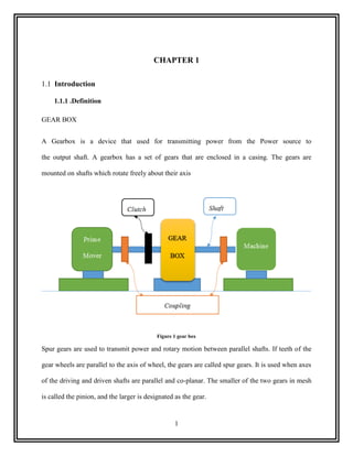
  • 1. 1 CHAPTER 1 1.1 Introduction 1.1.1 .Definition GEAR BOX A Gearbox is a device that used for transmitting power from the Power source to the output shaft. A gearbox has a set of gears that are enclosed in a casing. The gears are mounted on shafts which rotate freely about their axis Figure 1 gear box Spur gears are used to transmit power and rotary motion between parallel shafts. If teeth of the gear wheels are parallel to the axis of wheel, the gears are called spur gears. It is used when axes of the driving and driven shafts are parallel and co-planar. The smaller of the two gears in mesh is called the pinion, and the larger is designated as the gear.
  • 2. ` 2 Reduction gear box consists of 2 gears having same no. Of teeth but different diameters. The number of teeth is proportional to the circumference of the gear; the smaller circumference gear will have fewer teeth than the larger one. The smaller gear makes two revolutions for every one revolution of large gear. The amount of torque obtained at larger gear is twice comparing to the torque available in smaller gear. The speed of the output gear is decreases and the torque is increasing proportionally Function of gear box  In the most basic sense, a gear box function like any system of gears.it alters torque and speed between a driving device like a motor and a load. The gearbox is a mechanical method of transferring energy from one device to another and is used to increase torque while reducing speed. See in gear box design as we increase speed we decrease the torque this mean speed and torque have inverse relationship in this case. In general gear has three main functions in gear box or in any system  To control speed at the same time to control torque  To change the direction of motion  To transfer power 1.1.2 Principle of operation The gears and shafts present in the reduction gearbox undergo various forces acting over them. The two stage reduction gearbox consists of three shafts and four gears (two driver gears, two driven gears). The driver gear of the first stage of reduction which is probably the smallest gear in the entire reduction gear box is present on the input shaft which gets the input And the second
  • 3. ` 3 shaft also called as the intermediate shaft consists of the driven gear of the first stage of reduction a`nd also the driver gear of the second stage of reduction which are termed to be as compound gears. Finally, the third shaft called as the output shaft consists of the driven gear of the second stage of reduction which could be the largest gear 1.1.3 Application Application of bevel gear and spur gear  Automobile deferential (bevel gear)  Material handling equipment (bevel gear)  Food canning equipment (bevel gear)  Food packaging equipment (bevel gear)  Clock and watches(for spur gear)  Washing machine (for spur gear)  Gear pumps(for spur gear)  Motorcycle gear box(for spur gear) Bevel gear Used to transmit the power and motion between two intersecting shaft by the changing profile we can transmit power and motion two shafts which are not exactly
  • 4. ` 4 1.1.4 Advantage and disadvantage Advantage of bevel gear and spur gear  It can operate under high speed and high load (bevel gear)  Its suitable for 1:1 velocity ratio at an angel (bevel gear)  It has simple in construction(for spur gear)  It has easy to manufacture(for spur gear)  It has low cost(for spur gear)  It has excellent precision rating (for spur gear) Disadvantage of bevel gear and spur gear  It‟s complicated in design and manufacturing(bevel gear)  It requires more precision(bevel gear)  Center distance is limited (for spur gear)  Noise at high speed(for spur gear)  Large amount of stress (for spur gear)
  • 5. ` 5 1.2 Background 1.2.1 Definition GEARS A Gear is a rotating machine part having cut teeth, which mesh with another toothed part to transmit torque. Geared devices can change the speed, torque, and direction of a power source. Gears almost always produce a change in torque, creating a mechanical advantage, through their ratio. The teeth on the two meshing gears all have the same shape. Two or more meshing gears, working in a sequence, are called a gear train or a transmission. 1.2.2 Historical development of gear Gears were a logical continuation of the invention of the wheel. That gears are called the biggest invention after the wheel is not unthinkable. In any case, we can‟t live a normal day in our lives without gears: without gears no production, no energy and no transport. The use of gears is so obvious that we never dwell on where they come from. In this article, out of respect for the gear, we will detail the interesting history. Until now, the Greeks were given the honor of the invention of the wheel. Estimated that they were first used 300 years BC in Alexandria for the first time this mechanism. From unofficial writings show that in China already 800 v.C. differentials (a system of gears) were made. The first gears were made of wood, with wooden rods and teeth. Worn teeth could thus be replaced separately.
  • 6. ` 6 By the year 100 v.C. the Greeks used metal gears with cylindrical teeth in complex computing equipment and astronomical calendars. We know this by the discovery of the Antikythera Mechanism (see picture), the oldest known gear machine. This around 100 v.C. produced mechanism was found in 1900 in a wreck off the coast of the Greek island of Antikythera. The mechanism contains more than 30 gears for complicated astronomical calculations of time. Was this actually the first computer/ in later centuries, the gear was one of the most important parts of modern technology, incorporated into almost all the mechanisms, machines and vehicles. [ ] 1.2.3 Components of a gearbox A Gearbox comprises of major components namely  Casing  Gears  Shafts  Bearings
  • 7. ` 7 Casing Casing is a fixture that fixes all the shafts and assembles all gears into an assembly without any interference. Casing also contains the mounting points to mount it in a powertrain Assembly. The Casing takes the load imposed by the power source. Vibrations are also transmitted in case the power source is an Engine over the years; Cast Iron is being used for manufacturing casing. Nowadays, casings are coming in Steels or oven Aluminum Alloys. Gears Gears are mechanical components that have the ability to transmit motion from one shaft to another. The transmission of motion might not be uniform, and it can include changes indirection and torque. More specifically, gears can be described as toothed wheels which typically are round (but not necessarily) [1]. Gears have evolved from rolling cylinders, to wooden wheels with pegs, to the common gears used today which have specially shaped teeth that are shaped or cut into metal wheels. Shafts A shaft is a rotating machine element which is used to transmit power from one place to another. The power is delivered to the shaft by some tangential force and the resultant torque (or twisting moment) set up within the shaft permits the power to be transferred to various machines linked up to the shaft. In order to transfer the power from one shaft to another, the various members such as pulleys, gears etc., are mounted on it. Bearings
  • 8. ` 8 Bearing is a component that ensures smooth rotation between the fixed support and the rotating shafts. These components are made of high carbon alloy steels that can bear huge amount of loads and rotate at high RPMs/There are two types of bearing--- Sliding contact bearing and rolling contact bearings. Sliding contact have a fluid between the inner and outer race that ensures smooth rotation. Rolling contact bearings also known as ball bearings have a handful of tiny hardened steel balls or rollers between the inner and outer race, these balls are super finished and have less friction compared to the sliding contact bearings. 1.2.4 Classification of gears Figure 2 classification of gears 1.2.5 Types of Gears Spur gears, spur gears are used to transmit rotary motion between parallel shafts. They are cylindrical, and the teeth are straight and parallel to the axis of rotation and also they are used to transmit motion from one shaft to another the most common gears are spur gears and are used in
  • 9. ` 9 series for large gear reductions. Spur gears are used in washing machines, screwdrivers, windup alarm clocks, and other devices. Helical gears, helical gears are used to transmit motion between parallel or nonparallel shafts. Helical gears operate more smoothly and quietly compared to spur gears due to the way the teeth interact. The teeth on a helical gear cut at an angle to the face of the gear. The typical range of the helix angle is about 15 to 30 deg. Bevel gears, Bevel gears are used to transmit rotary motion between intersecting shafts. The tooth of the bevel gears can be cut straight or spiral. Have teeth formed on conical surfaces and are used mostly for transmitting motion between intersecting shafts. The figure actually illustrates straight-tooth bevel gears. Spiral bevel gears are cut so the tooth is no longer straight, but forms a circular arc. Hypoid gears are quite similar to spiral bevel gears except that the shafts are offset and nonintersecting. Worm gears, Worm gear sets are used to transmit rotary motion between nonparallel and nonintersecting shafts consist of a worm and a worm wheel.. Worm gear drives are used for shafts, the axes of which do not intersect and are perpendicular to each other. Worm gear drives are characterized by high speed reduction ratio. The direction of rotation of the worm gear, also called the worm wheel, depends upon the direction of rotation of the worm and upon whether the worm teeth are cut right-hand or left-hand. Worm gear sets are also made so that the teeth of one or both wrap partly around the other. Such sets are called single enveloping and double- enveloping worm gear sets. Worm gear sets are mostly used when the speed ratios of the two shafts are quite high, say, 3 or more.
  • 10. ` 10 1.2.6 Working principles of various types 1.3 Objective 1.3.1 General objective The general objective of this project is to design Gear Box with the details drawing 1.3.2 Specific objective Design and considering the following part Parts to be designed  To designed the component of gear box  To designed the part of gear box  To designed the part drawing of gear box  To designed the assembly of gear box 1.4 Scope The scopes are: Detail design a gear reducer at the following design specification my gear box type give from teacher is Intersecting fist stage bevel and second spur gear type the stage will be two stage, the rated power 4.8hp and input speed 1650rpm, usually low shock level, occasional shock Literature review on speed reducer gearbox and gear Design speed reducer gearbox using detail drawing
  • 11. ` 11 MATERIAL SELECTION RECOMMENDATION LITERATURE REVIEW RESULT & DISCUSSION SYNTHESIZE DESIGN ANALYSIS NEED OR AIM CONCLUSION DETAIL DRAWING 1.5 Methodology This project has 4 chapters. And we can classify them in to two major parts. The first part is an introductory part and the second part is literature review part and other part will be analysis of the project by using the force analysis, geometrical analysis as well as the detail drawing. Finally this project design is focus on the gear box design which is different parameters such as force; stresses etc. are calculated by numerical method. Generally describe by using block diagram of methodology as follow
  • 12. ` 12 1.6 Limitation In the design of Gear box we have faced so many limitations including:  Lack of resource i.e. computer access, Mat lab, and other software‟  Lack of comfortable area by means of political problem in the university.
  • 13. ` 13 CHAPTER 2 2.1 Literature Review For design of a gear box, it is necessary to look into the design aspects and literature available in order to better understand the designing aspects Prof. K.Gopinath & Prof. M.M.Mayuram in which he conclude that History of gears, Definition of gears, Types of gears and their applications. Spur Gear and Helical Gear provide by using pdf. Prof. A. V. Patil Faculty Department of Mechanical Engineering S.S.G.B.C.O.E India work on “Stress and Design Analysis of Triple Reduction Gearbox Casing” This work focuses on the stress analysis of triple reduction of gearbox casing designed and manufactured by steward Ramesh Banothu worked on „Design and analysis of Gear Shaft‟ in which he concluded that Vibrations can be transmitted from the casing to the gears through the gear shafts. He even conclude that the shafts are subjected to bending moments and slight torsion when there are at least two gears mounted on one shaft. Vilas Warudkar from his study „Design and Optimization of 2-Stage Reduction Gearbox‟ has concluded the methodology to make a conventional Reduction gearbox for Water pumps. This Gearbox did not use any alloys for materials and did not consider vibrations or Thermal analysis inside the Gearbox. Ralph E.Taggert made a detailed experimental study on „Forces that affect the operation and efficiency of reduction Gearbox‟ that contributes the complete information about a single stage reduction gearbox
  • 14. ` 14 Machine Company These gearboxes are designed for high torque and low speed applications for operating movable bridges, heavy hoisting machinery, or other lifting mechanisms. Chandresh Motka Assistant Professor Department of Mechanical Engineering Kalol Institute of Technology and Research Center, Kalol “Analysis & Optimization of Gearbox Efficiency- A Review” focus on The less efficiency of gear box of a machine tool is a serious problem as it increases maintenance cost and also affects the reputation of a firm. Hence its life has to be increased and should be made more reliable. The Volvo Group [1] introduced a concept of Automatic Transmissions. It is discussed that Manual Gearboxes are complicated in design and is difficult for the users to drive the vehicle. Usage of so many components in the manual gearbox also reduced the efficiency and the clutch plates had to be replaced periodically. The company stated that it is difficult to implement manual gearbox in smaller vehicles
  • 15. ` 15 CHAPTER 3 3.1 Material selection The first step in the gearbox design process is to select the material. A material is to be selected by doing intensive research on the properties of the various materials. Shaft material A shaft is a rotating machine element which is used to transmit power from one place to another. The power is delivered to the shaft by some tangential force and the resultant torque (or twisting moment) set up within the shaft permits the power to be transferred to various machines linked up to the shaft. In other words, we may say that a shaft is used for the transmission of torque and bending moment. The various members are mounted on the shaft by means of keys or splines. Material Used for Shafts the material used for shafts should have the following properties:  It should have high strength.  It should have good machinability.  It should have low notch sensitivity factor.  It should have good heat treatment properties.  It should have high wear resistant properties. The material used for ordinary shafts is carbon steel of grades 40 C 8, 45 C 8, 50 C 4 and 50 C12. The mechanical properties of these grades of carbon steel are given in the following table
  • 16. ` 16 Table 1 Mechanical properties of steels used for shafts Table 14.1[ ] When a shaft of high strength is required, then an alloy steel such as nickel, nickel-chromium or chrome-vanadium steel is used 45C8 carbon steel is selected as shaft material due to its better mechanical properties Material for Gears For choosing the material and designing the gears, the following data should be given: In the design of a gear drive, the following data is usually given:  The power to be transmitted.  The speed of the driving gear,  The speed of the driven gear or the velocity ratio, and  The center distance. The following requirements must be met in the design of a gear drive:  The gear teeth should have sufficient strength so that they will not fail under static loading or dynamic loading during normal running conditions.  The gear teeth should have wear characteristics so that their life is satisfactory.  The use of space and material should be economical.  The lubrication of the gears must be satisfactory.
  • 17. ` 17 For the pinion For the pinion selected material the cast iron is obtained by re-melting pig iron with coke and limestone in a furnace known as cupola. It is primarily an alloy of iron and carbon. The carbon contents in cast iron vary from 1.7 per cent to 4.5 per cent. It also contains small amounts of silicon, manganese, phosphorous Since the cast iron is a brittle material, therefore, it cannot be used in those parts of machines which are subjected to shocks. The properties of cast iron which make it a valuable material for engineering purposes are its low cost, good casting characteristics, high compressive strength, wear resistance and excellent machinability. The compressive strength of cast iron is much greater than the tensile strength. Following are the values of ultimate strength of cast iron  Tensile strength = ( )  Compressive strength = ( )  Shear strength = ( ) Cast iron has a various types i selected grey cast iron it has a low tensile strength, high compressive strength and no ductility. It can be easily machined. A very good property of grey cast iron is that the free graphite in its structure acts as a lubricant. Due to this reason, it is very suitable for those parts where sliding action is desired. Table 2 grey cast iron table 2.8(6)
  • 18. ` 18 For the gear For the gear selected material for the same as shaft The material used for ordinary gear is carbon steel of grades 40 C 8, 45 C 8, 50 C 4 and 50 C12. The mechanical properties of these grades of carbon steel are given in the above table1. When a shaft of high strength is required, then an alloy steel such as nickel, nickel-chromium or chrome-vanadium steel is used 45C8 carbon steel is selected as shaft material due to its better mechanical properties Casting Design An engineer must know how to design the castings so that they can effectively and efficiently render the desired service and can be produced easily and economically. In order to design a casting, the following factors must be taken into consideration …page 56[ ]  The function to be performed by the casting,  Soundness of the casting,  Strength of the casting,  Ease in its production,  Consideration for safety, and  Economy in production In rolling contact bearings, the contact between the bearing surfaces is rolling instead of sliding as in sliding contact bearings
  • 19. ` 19 Advantage of bearing  Low starting and running friction except at very high speeds.  Accuracy of shaft alignment.  Low cost of maintenance, as no lubrication is required while in service.  Small overall dimensions.  Easy to mount and erect.  Cleanliness. The rolling contact bearings, depending upon the load to be carried, are classified as : (a) Radial bearings, and (b) Thrust bearings When a split bearing is used, the bearing cap is tightened on the top. The load is usually carried by the bearing and not the cap, but in some cases e.g. split connecting rod ends in double acting steam engines, a considerable load comes on the cap of the bearing. Therefore, the cap and the holding down bolts must be designed for full load
  • 20. ` 20 CHAPTER 4 4.1 Design Analysis 4.4.1 Design of first stage (bevel gear) For satisfactory operation of the bevel gears, the face width should be from 6.3 m to 9.5 m, where m is the module. Also the ratio L / b should not exceed 3. For this, the number of teeth in the pinion must not less than 48. For the analysis we have to assume that teeth of pinion And the velocity ratio V.R=2 Now Pitch angle for the pinion , ( ) ( ) Pitch angle for the gear,
  • 21. ` 21 We know that the equivalent (or formative) number of teeth, Lewis factor 𝑌 = 𝜋 ∗ 𝑦 where Tooth form factor (or Lewis factor) for pinion 𝑌 ( ) Tooth form factor (or Lewis factor) for Gear 𝑌 ( ) Since the allowable static stress ( ) for both the pinion and gear is same (i.e. 140 MPa or N/mm2 ) and 𝑌 is less than𝑌 , therefore the pinion is weaker. Thus the design should be based upon the pinion. Torque on the pinion 𝜋 Where, s
  • 22. ` 22 𝜋 Tangential load on the pinion ∗ ∗ We know that pitch line 𝜋 ∗ ∗ 𝜋 ∗ ∗ 𝜋 ∗ ∗ 𝜋 ∗ ∗ Allowable working stress   We know that length of the pitch cone element or slant height element or slant height ∗ ∗ Since the face width (b) is 1/4th of the slant height of the pitch one .should not exceed 1/3th So let say 1/4th We know that tangential load on the pinion 𝜋 ∗ 𝑌 ( ) ( ) 𝜋 ∗ 𝑌 ( )
  • 23. ` 23 ( ) 𝜋 ∗ ( ) Solving this expression by hit and trial method, we find that Now The proportions for the bevel gears may be taken as follows ∗ ∗
  • 24. ` 24 ∗ ∗ 4.4.2 Design of a Shaft for Bevel Gears  Let assume that pressure angle of teeth is ° ,the pair of bevel gears connect two shaft at right angle and overhang =150mm[ ] Cone lengths L √ √ In designing a pinion shaft, the following procedure may be adopted 1. First of all, find the torque acting on the pinion. It is given by ∗ ∗ ∗ ∗ 2. Find the tangential force (WT) acting at the mean radius ( ) of the pinion. We know that But ( )
  • 25. ` 25 ( ) ∗ 3. Now find the axial and radial forces (i.e. WRH and WRV) acting on the pinion shaft as Discussed below. Now the radial force (WR) acting at the mean radius may be further resolved into two components, WRH and WRV, in the axial and radial directions as shown in Fig. . Figure 3 Forces acting on a bevel gear A little consideration will show that the axial force on the pinion shaft is equal to the radial force On the gear shaft but their directions are opposite. Similarly, the radial force on the pinion shaft is equal to the axial force on the gear shaft, but act in opposite directions.
  • 26. ` 26 There are three loads acting on bevel gear which are tangential force, axial and radial forces. The force relationships are The commonly used pressure angle for bevel gears is 14.5°, although pressure angles of 22.5° and 25° are used for heavy-duty drives. Therefore the axial force acting on the pinion shaft, ∗ ∗ And the radial force acting on the pinion shaft ∗ ∗ 4. Find resultant bending moment on the pinion shaft as follows :The bending moment due to and is given by
  • 27. ` 27 W 75mm 150mm We know that the torque transmitted by the shaft ∗ ∗ And we know that ∗ ∗ ∴ Tangential force on the pinion ∗ And the normal load acting on the tooth of the pinion Since the pinion is mounted at the end of the shaft, therefore maximum bending moment at the end of the pinion
  • 28. ` 28 First of all, considering the vertical loading at W. Let and be the reactions at the bearings A and B respectively. We know that Taking moments about A, ∗ ∗ ∗ ∗ Taking moments about B, ∗ ∗ ∗ ∗ The summation of vertical loading is Now considering horizontal loading at W. Let and be the reactions at the bearings A and B respectively. We know that there is no applied force in horizontally then the summation of horizontal force is zero ∴Resultant bending moment √
  • 29. ` 29 √ 5. Since the shaft is subjected to twisting moment (T ) and resultant bending moment (M),therefore equivalent twisting moment √ √ 6. Now the diameter of the pinion shaft may be obtained by using the torsion equation. We know that 𝜋 ∗ ∗ √ ∗ 𝜋 ∗ Where = Diameter of the pinion shaft,  = Shear stress for the material of the pinion shaft 7. Now the diameter of the gear shaft may be obtained by using the torsion equation. We know that 𝜋 ∗ ∗ √ ∗ 𝜋 ∗ Where = Diameter of the gear shaft,
  • 30. ` 30 4.4.3 Design of intermediate shaft A 50mm C D 50mm B 200mm We know that the torque transmitted by the shaft ∗ ∗ And we know that ∗ ∗ ∗ ∗ ∴ Tangential force on the Gear ∗ Assuming that the torque at C and D is same (i.e. 40836 N-mm), therefore tangential force on the gear C, acting downward ∴ Tangential force on the Pinion G E A R Pi ni o
  • 31. ` 31 ∗ Since the pinion is mounted at the right side of the shaft and the gear is mounted at the left side of the shaft therefore maximum bending moment at the both gear Now let us find the maximum bending moment for vertical and horizontal loading 50mm 200mm 50mm First of all, considering the vertical loading at W. Let and be the reactions at the bearings A and B respectively. We know that Taking moments about A, 𝑁 𝑁 𝑁
  • 32. ` 32 ∗ ∗ ∗ ∗ Taking moments about B, ∗ ∗ ∗ ∗ The summation of vertical loading is Now considering horizontal loading at W. Let and be the reactions at the bearings A and B respectively. We know that there is no applied force in horizontally then the summation of horizontal force is zero We know that Shear force.
  • 33. ` 33 Now let us find the maximum bending moment for vertical and horizontal loading. First of all, considering the vertical loading at C. Let RAV and RBV be the reactions at the bearings A and B respectively. We know that RAV + RBV = 680N Taking moments about A, we get RBV × 200 = 680 × 150 RBV = 680 × 150 / 200 = 510N RAV = 680 – 510 = 170 N We know that B.M. at A and B, MAV = MBV = 0 B.M. at D, MDV = RAV × 50 = 170 × 50 = 8500N-mm B.M. at C, MCV = RBV × 100 = 510 × 50 = 25500 N-mm Now considering horizontal loading at D. Let RAH and RBH be the reactions at the bearings A and B respectively. We know that RAH + RBH = 425N Taking moments about A, we get RBH × 200 = 50*425 = 425 × 50/ 200 = 106.25N RAH = 425– 106.25 = 318.75 N
  • 34. ` 34 We know that B.M. at A and B, MAH = MBH = 0 B.M. at D, MDH = RAH × 50 = 318.75 × 50 = 15937.5 N-mm B.M. at C, MDH = RBH × 50 = 106.25 × 50 = 5312.5 N-mm We know that resultant B.M. at C, √ √ And resultant B.M. at C, √ √ We see that the bending moment is maximum at C. ∴Resultant maximum bending moment Since the shaft is subjected to twisting moment (T ) and resultant bending moment (M),therefore equivalent twisting moment √ √
  • 35. ` 35 1. Now the diameter of the pinion shaft may be obtained by using the torsion equation. We know that 𝜋 ∗ ∗ √ ∗ 𝜋 ∗ Where = Diameter of the pinion shaft,  = Shear stress for the material of the pinion shaft 2. Now the diameter of the gear shaft may be obtained by using the torsion equation. We know that 𝜋 ∗ ∗ √ ∗ 𝜋 ∗ Where = Diameter of the gear shaft, 4.4.4 Key Design Calculation A key is a piece of mild steel inserted between the shaft and hub or boss of the pulley to connect these together in order to prevent relative motion between them. It is always inserted parallel to the axis of the shaft. Keys are used as temporary fastenings and are subjected to considerable crushing and shearing stresses. A keyway is a slot or recess in a shaft and hub of the pulley to accommodate a key. There are different types of key but I well select key is rectangular sunk key
  • 36. ` 36 Figure 4 rectangular key The sunken keys are provided half in the keyway of the shaft and half in the keyway of the hub or boss of the pulley. Width of key, w = d / 4; and thickness of key, t = 2w / 3 = d / 6 Where d = Diameter of the shaft or diameter of the hole in the hub  The rectangular key is designed as discussed below: Table 3 Proportions of standard parallel, tapered and gibe head keys. From Table 13.1,[ ] 4.4.5 Design of a key for first stage (Bevel Gears)
  • 37. ` 37 Where D= = 22mm Now from the table we gave the width and thickens of key (i.e., 3mm and 3mm respectively) We know that shear stress τ=42MPa Crushing stress The length of key is obtained by considering the key in shearing and crushing. Let l = Length of key. Considering shearing of the key. For gear We know torsional shearing strength (or torque transmitted) of the shaft ……………………..( ) And we know that shearing strength (or torque transmitted) of the key, ……………………( ) From equations (i) and (ii), we have Now considering crushing of the key. We know that shearing strength (or torque transmitted) of the key, ………………( ) From equations (ii) and (iii), we have Taking larger of the two values, we have length of key,
  • 38. ` 38 4.4.6 Design of second stage (spur gear) From the first we have power transmitted of 3528watts and the output speed of the first stage is input speed of the second stage and the second stage of gear ratio is 3:1 And also the pressure angel is 20° The number of teeth on the pinion (TP) in order to avoid interference may be obtained from the Following relation: ∗ [√ ( ) ] Where =1module G=Gear ratio =Pressure angle or angle of obliquity ∗ [√ ( ) ] ∗ ∗ The following table shows the values of service factor for different types of loads
  • 39. ` 39 Table 4 Values of service factor Table 28.10[6] So assume that the reduction transition gear works 10houre per day the value of service factor became 1.54 In order to design spur gear the following producer may be followed  First of all to design tangential tooth load is obtain from the power transmitted and the pitch live velocity by using the following relation ∗ Where Permissible tangential tooth load in newton, P = Power transmitted in watts, *v = Pitch line velocity in m / s, D = Pitch circle diameter in meters 𝜋 ∗ ∗ ∗ 𝜋 ∗ ∗ ∗ ∗ ∗
  • 40. ` 40  Apply the Lewis equation as follows 𝑦 But ∗ And we have Now Apply the Lewis equation ∗ 𝜋 𝑦 ∗ 𝜋 𝑦 The face width (b) may be taken as 3 pc to 4 pc (or 9.5 m to 12.5 m) for cut teeth and 2 pc to 3 pc (Or 6.5 m to 9.5 m) for cast teeth for 3pc =3*m* Tooth from factory y for 20° 𝑌 𝑌 Then ∗ 𝜋
  • 41. ` 41 Solving this expression by hit and trial method, we find that Now pc =3*m* * mm ∗  Calculate the dynamic load (WD) on the tooth by using Buckingham equation, i.e. ∗ ∗ ( ) ∗ √ In calculating the dynamic load (WD), the value of tangential load (WT) may be calculated by Neglecting the service factor (CS) i.e.
  • 42. ` 42 The value of deformation factor given below table Table 5 Values of deformation factor (C ). Table 28.5.[6] Before that we need have yon know the value of tooth error(e) in action also the value taken from the table
  • 43. ` 43 Table 6 Values of tooth error in action (e) verses module Table 28.7(6) From the above table we get the value of deformation factors C=770Nmm and tooth error in action e=0.0700mm Now ∗ ∗ ( ) ∗ √ ∗ ∗ ( ∗ ) ∗ √ ∗ Find the static tooth load (i.e. beam strength or the endurance strength of the tooth) by using The relation, ∗ ∗ ∗ 𝑦 ∗ ∗ 𝜋 ∗ 𝑦 For safety against breakage, WS should be greater than WD.
  • 44. ` 44 From the table below we have the value of surface endurance limit Table 7 Values of surface endurance limit Table 28.9.[6] Let take the value 320mpa ∗ ∗ ∗ 𝑦 ∗ ∗ 𝜋 ∗ 𝑦 ∗ ∗ ∗ 𝑦 ∗ ∗ 𝜋 ∗  Finally, find the wear tooth load by using the relation By using this formula ∗ ∗ ∗ Where =wear tooth gear
  • 45. ` 45 =diameter of the pinion b=face width =ratio factor ∗ ∗ = Load-stress factor (also known as material combination factor) in N/mm2. = ( ) ( ) = ( ) ( ) Then ∗ ∗ ∗ ∗ ∗ ∗ 4.4.7 Design of Shaft for Spur Gears In order to find the diameter of shaft for spur gears, the following procedure may be followed 50mm 200mm
  • 46. ` 46 We know that the torque transmitted by the shaft ∗ ∗ And we know that ∗ ∗ ∴ Tangential force on the pinion ∗  First of all, find the normal load (WN), acting between the tooth surfaces. It is given by Where WT = Tangential load, and = Pressure angle.=20° A thrust parallel and equal to WN will act at the gear center as shown in Fig. 5. Figure 5 Load acting on the gear  The weight of the gear is given by
  • 47. ` 47 ∗ ∗ Where TG = No. of teeth on the gear, b = Face width in mm, and m = Module in mm ∗ ∗ ∗ ∗ ∗  Now the resultant load acting on the gear √ ∗ √ ∗ ∗ If the gear is overhung on the shaft, then bending moment on the shaft due to the resultant Since the gear is mounted at the end of the shaft, therefore maximum bending moment at the end of the gear First of all, considering the vertical loading at W. Let and be the reactions at the bearings A and B respectively. We know that Taking moments about A,
  • 48. ` 48 ∗ ∗ Taking moments about B, ∗ ∗ ∗ ∗ The summation of vertical loading is Now considering horizontal loading at W. Let and be the reactions at the bearings A and B respectively. We know that there is no applied force in horizontally then the summation of horizontal force is zero 𝑁 𝑁 𝑁𝑚
  • 49. ` 49 We know that Shear force. We know that B.M. at A and B, MAV = MBV = 0 B.M. at C, MCV = Wt× 50 = 872 × 50 = 43600 N-mm=43.6Nm ∴Resultant bending moment √ √ 1. Since the shaft is subjected to twisting moment (T ) and resultant bending moment (M),therefore equivalent twisting moment √ √ 2. Now the diameter of the pinion shaft may be obtained by using the torsion equation. We know that 𝜋 ∗ ∗
  • 50. ` 50 √ ∗ 𝜋 ∗ Where = Diameter of the pinion shaft,  = Shear stress for the material of the pinion shaft 3. Now the diameter of the gear shaft may be obtained by using the torsion equation. We know that 𝜋 ∗ ∗ √ ∗ 𝜋 ∗ Where = Diameter of the gear shaft, Design of a key for second stage (spur Gears) The sunken keys are provided half in the keyway of the shaft and half in the keyway of the hub or boss of the pulley. Width of key, w = d / 4; and thickness of key, t = 2w / 3 = d / 6 Where d = Diameter of the shaft or diameter of the hole in the hub  The rectangular key is designed as discussed above: Where D= = 25mm Now from the table we gave the width and thickens of key (i.e., 3mm and 3mm respectively)
  • 51. ` 51 We know that shear stress τ=42MPa Crushing stress The length of key is obtained by considering the key in shearing and crushing. Let l = Length of key. Considering shearing of the key. For gear We know torsional shearing strength (or torque transmitted) of the shaft ……………………..( ) And we know that shearing strength (or torque transmitted) of the key, ……………………( ) From equations (i) and (ii), we have Now considering crushing of the key. We know that shearing strength (or torque transmitted) of the key, ………………( ) From equations (ii) and (iii), we have Taking larger of the two values, we have length of key,
  • 52. ` 52 4.4.8 Design of bearing Standard Dimensions and Designations of Ball Bearings The dimensions that have been standardized on an international basis are shown in Fig. 6. These dimensions are a function of the bearing bore and the series of bearing. The standard dimensions are given in millimeters. There is no standard for the size and number of steel balls. Figure 6 Standard designations of ball bearings Figure 7 Standard designa The bearings are designated by a number. In general, the number consists of at least three digits. Additional digits or letters are used to indicate special features e.g. deep groove, filling notch etc. The last three digits give the series and the bore of the bearing. The last two digits from 04 onwards, when multiplied by 5, give the bore diameter in millimeters. The third from the last digit designates the series of the bearing. The most common ball bearings are available in four series as follows: 1. Extra light (100),
  • 53. ` 53 2. Light (200), 3. Medium (300), select this 4. Heavy (400) The following table shows the principal dimensions for radial ball bearings…from table 27.1 [ ] Table 8 Principal dimensions for radial ball bearings. Table 27.1. [6] Bearing no Bore mm Outside diameter mm Width mm 200 10 30 9 304 20 52 14 404 20 72 19
  • 54. ` 54 CHAPTER 5 2.1 Result and Discussion Design of first stage (bevel gear) Design of second stage (spur gear) Velocity ratio V.R=2:1 Velocity ratio V.R=2:1 Teeth of pinion Teeth of pinion Teeth of gear Teeth of gear Speed of pinion Speed of pinion Speed of gear Speed of gear Pitch angel for pinion Pitch line velocity Pitch angel of gear Lewis factor 𝑌 Formative no of pinion Tangential load Formative no of gear Face width b=23.56mm Lewis factor for pinion 𝑌 Module m=2 Lewis factor for gear 𝑌 Dynamic load Torque of the pinion T=20420Nmm Endurance strength Tangential of pinion Design of shaft bevel gear Pitch line velocity V=9m/s Tangential force Length of pitch cone L=108mm Mean radius Face width b=15mm Axial force on shaft Module m=2 Radial force on shaft Addendum a=2mm Total bending moment M=2.3Nm Duodenum d=2.4mm Twisting moment
  • 55. ` 55 Clearance c=0.4mm Dia of pinion shaft Working depth =4mm Dia of gear shaft Thickness of tooth t=3mm Design of shaft spur gear Diameter of pinion Normal load Diameter of gear Weight of gear Design of key bevel gear Total load on shaft Thickness of key Total bending moment M=130.8Nmm Width of key Twisting moment Length of key Dia of pinion shaft Design of key spur gear Dia of gear shaft Thickness of key Width of key Length of key
  • 56. ` 56 CHAPTER 6 9.1 Conclusion and Recommendation Conclusion the conclusion from this project we design that the intersecting gearbox it to transmit 3.8hp, and has gear reduction of two, by using spur gear as output and bevel gear as input also having intermediate shaft. It has bearing at input, intermediate and output. Which is made from carbon steel can withstand any difficulty without failure or it is safe at given power and rotational speed for a give life time. Recommendation When we design some part we have to collect information from different source. This means the design is performed by using many references and web sites. So the materials needed for design case must be fulfilled in order to perform applicable design for all users. The design progress was decent, but the given time to finish the design was very short compared to the hugeness of the design. So, I recommended for the future the time allowed should be enough to finish the design .
  • 57. ` 57 Reference 1. Drago, R. J. (1988). Fundamentals of Gear Design. Boston, MA: Butterworths. 2. AGMA Design Manual for Bevel Gears, 2005 3. AGMA Rating Standard for Bevel Gears, 2003 4. http://www.skf.com/skf/productcatalogue/jsp/viewers/productTableViewer.jsp?&l ang=en&newlink=1&tableName=1_1_1&presentationType=3&startnum=15 5. V. B. Bhandari “Design of Machine Elements”, Tata McGraw Hill Publication, Third Edition 2010, p.p. 330 - 348, 646 – 70 6. A Textbook of Machine Design by R.S.KHURMI AND J.K.GUPTA [tortuka] 7. PSG design data book 8. (https://www.apexdyna.nl/en/gear-history/) 9. Mechanics of materials,9th edition by R.C.HIBBELER 10. Shigley‟s Mechanical Engineering Design - 8th edition 11. Design of Machine Elements By V B Bhandari 3Ed 12. Hid_Shigley's Mechanical Engineering Design - 8th Edition with Solution of Problems 13. Machine Design objective by V B Bhandari 14. Shigley's Mechanical Engineering Design 9th Edition 15. machine_design_databook
  • 58. ` 58 Appendices Table 9 Principal dimensions for radial ball bearings
  • 59. ` 59