Kuwait City MTP kit ((+919101817206)) Buy Abortion Pills Kuwait
Smart grid management an overview
1. Smart Management of Electric Power Grid: An Overview
Dr. S.K. Srivastava
Dept. of Electrical Engineering
Madan Mohan Malviya University of Technology
Gorakhpur, India
Abstract: Due to frequently occurrence of blackouts in recent past, worldwide, have necessitated the use of more
intelligent and automated systems for online monitoring, protection and control of power systems. Security needs
are required to be systematically addresses to mitigate future vulnerability of the system. Wide Area Monitoring,
Protection and Control (WAMPC) systems with intelligent grid control are being increasingly used in power
system network to enhance the grid security. The smart grid regarded as the next future generation power grid, it is
also called a intelligent grid or future grid, uses two-way flow electricity and information i.e. from the grid to user
and from user to grid by this way its create widely distributed automated energy delivery network which is not
possible in a traditional grid which is a single way of electricity flow i.e. from grid to user. In this paper it has
explored comparative analysis of smart grid with traditional grid and also explain some of term which is mostly
require in smart grid like communication channel between the service provider and the user, smart meter,
distributed generation.
Index terms: smart grid, information transfer, distributed generation, smart meter.
(1) Introduction: Traditionally, the grid is used for the
electricity system may support all or some of the following
four operations; electricity generation, electricity
transmission, electricity distribution and electricity control.
The traditional power grids are generally used to carry power
from a few central generators to a large number of users or
customers. But in case of smart grid user two-way flow of
electricity and information to create an automated and
distributed advanced energy delivered network. For instance,
once a medium voltage transformer failure occur in the
distribution grid ,the traditionally take to much time to
correct its but in case of smart grid may automatically
change the power flow and recover the power delivery
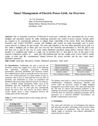
service. Below shown a brief comparison between the
existing grid with the smart grid.
Table 1: A brief comparison between the existing grid and
smart grid.
Existing Grid Smart Grid
Electromechanical Digital
One-way communication Two-way communication
Centralized generation Distributed generation
Few sensors Sensor throughout
Manual monitoring Self monitoring
Manual restoration Self healing
Failure and blackouts Adaptive and islanding
Limited control Pervasive control
Few customer choices Many customer choices
The ultimate smart grid is a vision. It is a loose integration of
complementary component, subsystems, functions and
service under the pervasive control of highly intelligent
management and control system. The smart grid represents
the full suite of current and proposed responses to the
challenges of electricity supply. Because of the diverse range
of factors there are numerous competing taxonomies and no
agreement on a universal definition. Nevertheless, one
possible categorisation is given here;
1.1 Reliability;
The smart grid will make use of technologies that improve
fault detection and allow self-healing of the network without
the intervention of technicians. This will ensure more
reliable supply of electricity, and reduced vulnerability to
natural disasters or attack.
2. 1.2 Flexibility in network topology;
Next-generation transmission and distribution infrastructure
will be better able to handle possible bidirectional energy
flows, allowing for distributed generation such as from
photovoltaic panels on building roofs, but also the use of fuel
cells, charging to/from the batteries of electric cars, wind
turbines, pumped hydroelectric power, and other sources.
Classic grids were designed for one-way flow of electricity,
but if a local sub-network generates more power than it is
consuming, the reverse flow can raise safety and reliability
issues. A smart grid aims to manage these situations.
1.3 Efficiency;
Numerous contributions to overall improvement of the
efficiency of energy infrastructure is anticipated from the
deployment of smart grid technology, in particular including
demand-side management, for example turning off air
conditioners during short-term spikes in electricity price.
The overall effect is less redundancy in transmission and
distribution lines, and greater utilization of generators,
leading to lower power prices.
1.4 Load adjustment;
The total load connected to the power grid can vary
significantly over time. Although the total load is the sum of
many individual choices of the clients, the overall load is not
a stable, slow varying, cement of the load if a popular
television program starts and millions of televisions will
draw current instantly. Traditionally, to respond to a rapid
increase in power consumption, faster than the start-up time
of a large generator, some spare generators are put on a
dissipative standby mode.
.A smart grid may warn all
individual television sets, or another larger customer, to
reduce the load temporarily (to allow time to start up a larger
generator) or continuously (in the case of limited resources).
1.5 Sustainability
The improved flexibility of the smart grid permits greater
penetration of highly variable renewable energy sources such
as solar power and wind power, even without the addition of
energy storage. Current network infrastructure is not built to
allow for many distributed feed-in points, and typically even
if some feed-in is allowed at the local (distribution) level; the
transmission-level infrastructure cannot accommodate it.
Rapid fluctuations in distributed generation, such as due to
cloudy or gusty weather, present significant challenges to
power engineers who need to ensure stable power levels
through varying the output of the more controllable
generators such as gas turbines and hydroelectric generators.
Smart grid technology is a necessary condition for very large
amounts of renewable electricity on the grid for this reason.
2.0 What is Smart Grid?
The initial concept of smart grid started with the idea of
advanced metering infrastructure (AMI) with the aim of
improving demand side management and energy efficiency
and constructing self-healing reliable grid protection against
malicious storage and natural disaster. Smart Grid refer to a
class of technology people are using to bring utility
electricity deliver systems into the 21century using
computer-based remote control and automation .These
system are made possible by two-way communication
technology and computer processing that has been used for
decades in other industries. Each device on the network can
be given sensors to gather data (power meter, voltage
sensors, fault detectors etc.) plus two-way digital
communication between the device in the field and the
utility’s network operations center.
Whereas the traditional grid is based on design requirement
written in the 1950s, when the primary objective was to keep
the light on. This approach to electric power involves large,
centralized power plant that feed power over an elecro-
mechanical grid. In this producer controlled model, power
flow in one direction controlled model, power flow in one
direction only. There is no two-way communication that
allows interactivity between ends users and the grid. The
anticipated benefits and requirement of smart grid are the
following;
Improved power reliability and quality.
Optimizing facility utilization and averting construction
of back-up (peak load) power plants.
Enhancing capacity and efficiency of existing electric
power network.
Improving resilience to disruption
Enabling predictive maintenance and self-healing
responses to system disturbances;
Facilitating expanded deployment of renewable energy
sources;
Accommodating distributed power sources;
Automating maintenance and operation;
Reducing greenhouse gas emissions by enabling
electric vehicles and new power sources;
3. Reducing oil consumption by reducing the need for
inefficient generation during peak usage periods;
Presenting opportunities to improve grid security;
Enabling transition to plug-in electric vehicles and
new energy storage options;
Increasing consumer choice;
Enabling new products, services, and markets.
In order to realize this new grid paradigm, provided a
conceptual model (as shown in Fig. 1), which can be used as
a reference for the various parts of the electric system where
SG standardization work is taking place.
Figure 1: Conceptual model
The brief descriptions of the domains and actors are given
below:
Domain Actors in the Domain
Customers The end users of electricity. May also
generate,store, and manage the use of energy.
Markets The operators and participants in electricity
markets.
Service
Providers
The organizations providing services to
electrical customers and utilities.
Operations The managers of the movement of electricity.
Bulk
Generation
The generators of electricity in bulk
quantities. May also store energy for later
distribution.
Transmissi
on
The carriers of bulk electricity over long
distances. May also store and generate
electricity
Distributio
n
The distributors of electricity to and from
customers. May also store and generate
electricity.
3.0 Smart Grid Component;
(a) Smart Meter
(b) Information Transfer
(c ) Distributed Generation
(a) Smart Meter:- Smart metering is the most important
mechanism used in the SG for obtaining information from
end users’ devices and appliances, while also controlling the
behavior of the devices. Automatic metering infrastructure
(AMI) systems [1], which are themselves built upon
automatic meter reading (AMR) systems [2], are widely
regarded as a logical strategy to realize SG. AMR is the
technology of automatically collecting diagnostic,
consumption, and status data from energy metering devices
and transferring that data to a central database for billing,
troubleshooting, and analyzing. AMI differs from traditional
AMR in that it enables two-way communications with the
meter. Therefore nearly all of this information is available in
real time and on demand, allowing for improved system
operations and customer power demand management.
Smart meters, which support two-way communications
between the meter and the central system, are similar in
many aspects to AMI meters, or sometimes are regarded as
part of the AMI. A smart meter is usually an electrical meter
that records consumption in intervals of an hour or less and
sends that information at least daily back to the utility for
monitoring and billing purposes [3]. Also, a smart meter has
the ability to disconnect-reconnect remotely and controls the
user appliances and devices to manage loads and demands
within the future “smart-buildings.” Fig. 2 shows a typical
usage scenario for smart meters.
Fig. 2: An Example of the Smart Metering Structure:
4. The smart meter collects the power consumption information
of the dishwasher, TV, and the refrigerator, and also sends
the control commands to them if necessary. The data
generated by the smart meters in different buildings is
transmitted to a data aggregator. This aggregator could be an
access point or gateway. This data can be further routed to
the electric utility or the distribution substation.
From a consumer’s perspective, smart metering offers a
number of potential benefits. For example, end users are able
to estimate bills and thus manage their energy consumptions
to reduce bills. From a utility’s perspective, they can use
smart meters to realize real-time pricing, which tries to
encourage users to reduce their demands in peak load
periods, or to optimize power flows according to the
information sent from demand sides.
An important function in the vision of SG is monitoring and
measurement of grid status. We review the following two
major monitoring and measurement approaches, namely
sensors and phasor measurement units.
Sensors or sensor networks have already been used as a
monitoring and measurement approach for different
purposes [5]. In order to detect mechanical failures in power
grids such as conductor failures, tower collapses, hot spots,
and extreme mechanical conditions, Leon et al. [6] proposed
that sensor networks should be embedded into the power
grid and help to assess the real-time mechanical and
electrical conditions of transmission lines, obtain a complete
physical and electrical picture of the power system in real
time, diagnose imminent as well as permanent faults, and
determine appropriate control measures that could be
automatically taken and/or suggested to the system operators
once an extreme mechanical condition appears in a
transmission line. The use of sensor networks in the SG has
many requirements [7-9].
i) Quality-of-Service (QoS) requirements: The information
generated by sensor networks may be associated with some
data QoS requirements, such as reliability, latency, and
network throughput. For example, the critical sensed data
related to grid failures should be received by the controller in
a timely manner. The communication subsystem supporting
sensor networks must provide mechanisms to satisfy these
QoS requirements.
ii) Resource constraints: Sensor nodes are often low cost
and resource limited devices. Thus the control programs for
sensor networks should be energy efficient.
iii) Remote maintenance and configuration: Sensors must
be remotely accessible and configurable, so that the sensor
networks could be maintained remotely, conveniently, and
promptly.
iv) High security requirements: Security is very important
for electric power systems. By compromising sensors,
attackers can jeopardize the power grid operation.
v) Harsh environmental conditions: In SG environments,
sensors may be subject to radio frequency (RF) interference,
highly caustic or corrosive environments, high humidity
levels, vibrations, dirt and dust, or other conditions that may
cause a portion of sensor nodes to malfunction. Hence the
sensor network design must consider the survivability
requirement, i.e., the sensor network is still connected or the
critical areas are still monitored if some sensors fail.
Phasor Measurement Unit, use of phasor measurement units
(PMUs) to help create a reliable power transmission and
distribution infrastructure [10]. A PMU measures the
electrical waves on an electrical grid to determine the health
of the system. Technically speaking, a phasor is a complex
number that represents both the magnitude and phase angle
of the sine waves found in electricity. Phasor measurements
that occur at the same time are called synchrophasor, as are
the PMU devices that allow their measurement. Typically,
PMU readings are obtained from widely dispersed locations
in a power system network and synchronized using the
global positioning system (GPS) radio clock. With a large
number of PMUs and the ability to compare shapes from
alternating current (AC) readings everywhere on the grid,
system operators can use the sampled data to measure the
state of the power system and respond to system conditions
in a rapid and dynamic fashion. Refer to [11] for a technical
introduction to the PMU.
Phasor measurements using GPS based time synchronization
were introduced in the mid-1980s [12-15]. A Virginia Tech
research team developed the first prototype PMU in 1988
[16]. Later, the frequency monitoring network (FNET)
project utilized a network of low-cost, high-precision
frequency disturbance recorders to collect synchrophasor
data from the U.S. power grid [17]. Early research on the
applications of PMU technology was mainly focused on
validation of system models and accurate postmortem
analysis. However, now with wide-scale real-time PMU data
being obtainable, system operators have the capability of
deploying system state estimation procedures and system
protection functionalities in power grids, with the goal of
5. making the power system immune to catastrophic failures.
PMU is an exciting area being explored by both industry and
academia. Industry is investigating how to install the PMUs,
collect the data, and establish communication transfers of
this data to the utility control centers [18, 19]. In academia,
typical research fields are the applications of PMU for grid
protection functions, such as providing loss-of-mains
protection [20], monitoring fault event [21, 22, 23], locating
disturbance [24], estimating grid state [25, 26], studying
synchronous islanded operation [27], monitoring power
quality [28], and devising experimental applications for the
monitoring of active distribution grids [29].
(b) Information Management:
In SG, a large amount of data and information will be
generated from metering, sensing, monitoring, etc. SG must
support advanced information management. The task of the
information management is data modeling, information
analysis, integration, and optimization.
(i) Data Modeling:-As stated by IEEE P2030 [30], the goal
of SG information technology data modeling is to provide a
guide to creating persistent, displayable, compatible,
transferable, and editable data representation for use within
the emerging SG. In other words, the objective is to make it
as interoperable as possible using relevant standards. That is
specifically addressing the data that represents state
information about the grid and individual items in it. This
would include nearly all connected items from generation
down to individual consuming devices. They all have state
information that may need to be read, stored, transmitted,
etc. There is two reason of using of data modeling;
First, the information exchange between two application
elements is meaningful only when both of them can use the
information exchanged to perform their respective tasks.
Therefore, the structure and meaning of the exchanged
information must be understood by both application
elements. Although within the context of a single
application, developers can strive to make the meaning clear
in various user interfaces,when data is transferred to another
context (another system), the meaning could be lost due to
incompatible data representation. Considering that the SG is
a complicated system of systems, design of a generally
effective data representation is very important.
Second, the data modeling is also related to the system
forward compatibility and backward compatibility. On one
hand, a well-defined data model should make legacy
program adjustments easier. We hope that the data
representation designed for SG can also be (or at least
partially) understood by the current power system, in order
to take advantage of the existing infrastructure as much as
possible. On the other hand, thus far SG is more like a
vision. Its definition and functionality keep evolving.
Suppose that in the current implementation, all the data is
particularly designed to be stored in an optimized way that
can be understood by a current application X. After some
time, a new application Y is integrated into SG. Data
modeling is the key to whether this new application can
understand the historical data and obtain enough information
from the historical data.
ii) Information Analysis, Integration, and Optimization:
Information analysis is needed to support the processing,
interpretation, and correlation of the flood of new grid
observations, since the widely deployed metering and
monitoring systems in SG will generate a large amount of
data for the utility. As mentioned in [31], one part of the
analytics would be performed by existing applications, and
another part of the analytics dimension is with new
applications and the ability of engineers to use a workbench
to create their customized analytics dashboard in a self-
service model.
Information integration aims at the merging of information
from disparate sources with differing conceptual, contextual,
and typographical representations. In SG, a large amount of
information has to be integrated. First one, the data
generated by new components enabled in SG may be
integrated into the existing applications, and metadata stored
in legacy systems may also be used by new applications in
SG to provide new interpretations. Secondly, as stated in
[32, 33], currently most utility companies have limited
installed capability for integration across the applications
associated with system planning, power delivery, and
customer operations. In most cases, this information in each
department is not easily accessible by applications and users
in other departments or organizations. These “islands of
information” correspond to islands of autonomous business
activities. Therefore, the emerging SG calls for enterprise
level integration of these islands to improve and optimize
information utilization throughout the organization.
Information optimization is used to improve information
effectiveness. The data size in the future SG is expected to
be fairly large as a result of the large-scale monitoring,
sensing, and measurement. However,the generated data may
have a large amount of redundant or useless data. Therefore,
6. we need to use advanced information technology to improve
the information effectiveness, in order to reduce
communication burden and store only useful information.
There may be two type of communication technologies use
as in shown in figure 3,
Fig 3. Classification of Relevant Research in
Communication Technologies in SG
A communication subsystem in an SG must at least satisfy
the following basic requirements:
(a) The communication subsystem must support the quality
of service (QoS) of data [34]. This is because the critical
data (e.g. the grid status information) must be delivered
promptly.
(b) The communication subsystem must be highly reliable.
Since a large number of devices will be connected and
different devices and communication technologies will be
used, guaranteeing the reliability of such a large and
heterogeneous network is not a trivial task.
(c) The communication subsystem must be pervasively
available and have a high coverage. This is mandated by the
principle that the SG can respond to any event in the grid in
time.
(d) The communication subsystem must guarantee security
and privacy.
(C) Distributed Generation; Smarter power generation
becomes possible as the two-way flows of electricity and
information are supported. A key power generation
paradigm enabled by SG will be the distributed generation
(DG). DG takes advantage of distributed energy resource
(DER) systems (e.g. solar panels and small wind turbines),
which are often small-scale power generators (typically in
the range of 3 kW to 10,000 kW), in order to improve the
power quality and reliability. For example, a micro grid,
which is a localized grouping of electricity generators and
loads, can disconnect from the macro grid so that distributed
generators continue to power the users in this micro grid
without obtaining power from outside. Thus, the disturbance
in the macro grid can be isolated and the electric power
supply quality is improved. A study [35] from the
International Energy Agency pointed out that a power
system based on a large number of reliable small DGs can
operate with the same reliability and a lower capacity margin
than a system of equally reliable large generators. A review
of different distributed energy technologies such as micro
turbines, photovoltaic, fuel cells, and wind power turbines
can be found in [36].
4.0 CONCLUSION:
This paper explained how that smart grid improve existing
electrical infrastructure like reliability, efficiency,
economically, environmentally. Also by use of distributed
generation used like solar, wind etc we reduce the dependent
on conventional generation system and also reduce pollution
level. Using of smart meter consumer check price of supply
and used according to that i.e. save of money. By using of
smart grid it’s also help in automating maintenance and
operation of supply system and also reducing greenhouse gas
emissions by enabling electric vehicles and new power
sources.
REFERENCES:
1) D. G. Hart. Using AMI to realize the smart grid. IEEE
Power and Energy Society General Meeting 2008 -
Conversion and Delivery of Electrical Energy in the 21st
Century, pages 1–2, 2008
2) D. W. Rieken and M. R. Walker. Ultra low frequency
power-line communications using a resonator circuit. IEEE
Transcations on Smart Grid, 2(1):41–50, 2011.
3) Federal Energy Regulatory Commission. Assessment of
demand response and advanced metering. Staff Report,
http://www.ferc.gov/legal/staff-reports/2010-dr-report.pdf.
2010.
4) I. F. Akyildiz, W. Su, Y. Sankarasubramaniam, and E.
Cayirci. A survey on sensor networks. IEEE
Communications Magazine, 40(8):102–114, 2002.
7. 5) R. Leon, V. Vittal and G. Manimaran. Application of
sensor network for secure electric energy infrastructure.
IEEE Transactions on Power Delivery, 22(2):1021–1028,
2007.
6) V.C.Gungor and F.C.Lambert. A survey on
communication networks for electric system automation.
Computer Networks, 50(7):877–897, 2006.
7) V.C. Gungor, B. Lu, and G. P.Hancke. Opportunities and
challenges of wireless sensor networks in smart grid. IEEE
Transcations on Industrial Electronics, 57(10):3557–3564,
2010.
8) Y. Wang, W. Lin, and T. Zhang. Study on security of
wireless sensor networks in smart grid. 2010 International
Conference on Power System Technology, pages 1–7, 2010.
9) A.Armenia and J.H.Chow. A flexible phasor data
concentrator design leveraging existing software
technologies. IEEE Transactions on Smart Grid, 1(1):73–81,
2010.
10) J. De La Ree,V. Centeno, J. S. Thorp, and A. G. Phadke.
Synchronized phasor measurement applications in power
systems. IEEE Transcations on Smart Grid, 1(1):20–27,
2010.
11) P.Bonanomi. Phase angle measurements with
synchronized clocks principle and applications. IEEE
Transactions on Power Apparatus and Systems,
100(12):5036–5043, 1981.
12) A.G.Phadke and J.S.Thorp. Synchronized phasor
measurements and their applications. New York: Springer,
2008.
13) A.G.Phadke, J.S.Thorp, and M. G. A.Adamiak. A new
measurement technique for tracking voltage phasors, local
system frequency, and rate of change of frequency. IEEE
Transactions on Power Apparatus and Systems, PAS-
102(5):1025–1038, 1983.
14) V.Venkatasubramanian, H.Schattler, and J.Zaborszky.
Fast time varying phasor analysis in the balanced three-
phase large electric power system. IEEE Transactions on
Automatic Control, 40(11):1975–1982, 1995.
15) Y. Zhang, P. Markham, T. Xia, L. Chen, Y.Ye, Z. Wu,
Z. Yuan, L. Wang, J. Bank, J.Burgett, R.W.Conners and
Y.Liu. Wide-area frequency monitoring network (FNET)
architecture and applications. IEEE Transcations on Smart
Grid, 1(2):159–167, 2010.
16) R.F.Nuqui. State estimation and voltage security
monitoring using synchronized phasor measurements.
Doctor of Philosophy Dissertation, Virginia Polytechnic
Institute and State University.
17) IEEE Power Engineering Society. IEEE standard for
synchrophasors for power systems, IEEE Std C37, 118-
2005.
18) North American Synchro phasor Initiative, Performance
and Standard Task Team. A guide for PMU installation,
commissioning and maintenance, Part II, PMU installation
procedures. 2007.
19) D.M.Laverty, D.J.Morrow, R.J.Best, and P.A.Crossley.
Differential rocof relay for loss-of-mains protection of
renewable generation using phasor measurement over
internet protocol. 2009 CIGRE/IEEE PES Joint Symposium
on Integration of Wide-Scale Renewable Resources into the
Power Delivery System, pages 1–7, 2009.
20) O. Samuelsson, M. Hemmingsson, A. H. Nielsen, K. O.
H. Pedersen, and J. Rasmussen. Monitoring of power system
events at transmission and distribution level. IEEE
Transactions on Power System, 21(2):1007–1008, 2006.
21) J.Tate and T.Overbye. Line outage detection using
phasor angle measurements. IEEE Transactions on Power
Systems, 23(4):1644–1652, 2008.
22) J.Tate and T.Overbye. Double line outage detection
using phasor angle measurements. IEEE Power & Energy
Society General Meeting’09, pages 1–5, 2009.
23) J.Ma, P.Zhang, H. Fu, B. Bo, and Z. Dong. Application
of phasor measurement unit on locating disturbance source
for low-frequency oscillation. IEEE Transcation on Smart
Grid, 1(3):340–346, 2010.
24) M. Powalko, K. Rudion, P. Komarnicki, and J.
Blumschein. Observability of the distribution system. 20th
International Conference and Exhibition on Electricity
Distribution, pages 1–4, 2009.
25) M. Vaiman, M. Vaiman, S. Maslennikov, E. Litvinov,
and X. Luo. Calculation and visualization of power system
8. stability margin based on PMU measurements. IEEE
SmartGridComm’10, pages 31–36, 2010.
26) R. J. Best, D. J. Morrow, D. M. Laverty, and P. A.
Crossley. Synchrophasor broadcast over Internet protocol for
distributed generator synchronization. IEEE Transactions on
Power Delivery, 25(4):2835–2841, 2010.
27) A. Carta, N. Locci, and C. Muscas. GPS-based system
for the measurement of synchronized harmonic phasors.
IEEE Transactions on Instrumentation and Measurement,
58(3):586–593, 2009.
28) A. Borghetti, C. A. Nucci, M. Paolone, G. Ciappi, and A.
Solari. Synchronized phasors monitoring during the
islanding maneuver of an active distribution network. IEEE
Transcations on Smart Grid, 2(1):82–91, 2011.
29) IEEE. P2030/D7.0 draft guide for Smart Grid
interoperability of energy technology and information
technology operation with the electric power system (EPS),
and end-user applications and loads. 2011.
30) A. Ipakchi. Implementing the smart grid: Enterprise
information integration. Grid Wise Grid-Interpol; Forum,
pages 121.122–1 – 121.122–7, 2007.
31) J. Roncero. Integration is key to smart grid management.
IET-CIRED Seminar 2008: Smart Grids for Distribution,
pages 1–4, 2008.
32) H. Li and W. Zhang. Qos routing in smart grid. IEEE
Globecom’10, pages 1–6, 2010.
33) International Energy Agency. Distributed generation in
liberalized electricity markets 2002.
34) H. Zareipour, K. Bhattacharya, and C. Canizares.
Distributed generation: Current status and challenges.
NAPS’04, pages 1–8, 2004.