SlideShare a Scribd company logo
1 of 14
Download to read offline
Pressure measurement 1
Pressure measurement
The construction of a bourdon tube gauge, construction
elements are made of brass
Many techniques have been developed for the measurement of
pressure and vacuum. Instruments used to measure pressure are
called pressure gauges or vacuum gauges.
A manometer could also be referring to a pressure measuring
instrument, usually limited to measuring pressures near to
atmospheric. The term manometer is often used to refer
specifically to liquid column hydrostatic instruments.
A vacuum gauge is used to measure the pressure in a
vacuum—which is further divided into two subcategories: high
and low vacuum (and sometimes ultra-high vacuum). The
applicable pressure range of many of the techniques used to
measure vacuums have an overlap. Hence, by combining several
different types of gauge, it is possible to measure system pressure
continuously from 10 mbar down to 10
−11
mbar.
Absolute, gauge and differential pressures -
zero reference
Although no pressure is an absolute quantity, everyday pressure measurements, such as for tire pressure, are usually
made relative to ambient air pressure. In other cases measurements are made relative to a vacuum or to some other
ad hoc reference. When distinguishing between these zero references, the following terms are used:
• Absolute pressure is zero referenced against a perfect vacuum, so it is equal to gauge pressure plus atmospheric
pressure.
• Gauge pressure is zero referenced against ambient air pressure, so it is equal to absolute pressure minus
atmospheric pressure. Negative signs are usually omitted.
• Differential pressure is the difference in pressure between two points.
The zero reference in use is usually implied by context, and these words are only added when clarification is needed.
Tire pressure and blood pressure are gauge pressures by convention, while atmospheric pressures, deep vacuum
pressures, and altimeter pressures must be absolute. Differential pressures are commonly used in industrial process
systems. Differential pressure gauges have two inlet ports, each connected to one of the volumes whose pressure is
to be monitored. In effect, such a gauge performs the mathematical operation of subtraction through mechanical
means, obviating the need for an operator or control system to watch two separate gauges and determine the
difference in readings. Moderate vacuum pressures are often ambiguous, as they may represent absolute pressure or
gauge pressure without a negative sign. Thus a vacuum of 26 inHg gauge is equivalent to an absolute pressure of 30
inHg (typical atmospheric pressure) − 26 inHg = 4 inHg.
Atmospheric pressure is typically about 100 kPa at sea level, but is variable with altitude and weather. If the absolute
pressure of a fluid stays constant, the gauge pressure of the same fluid will vary as atmospheric pressure changes.
For example, when a car drives up a mountain (atmospheric air pressure decreases), the (gauge) tire pressure goes
up. Some standard values of atmospheric pressure such as 101.325 kPa or 100 kPa have been defined, and some
instruments use one of these standard values as a constant zero reference instead of the actual variable ambient air
pressure. This impairs the accuracy of these instruments, especially when used at high altitudes.
Use of the atmosphere as reference is usually signified by a (g) after the pressure unit e.g. 30 psi g, which means that
the pressure measured is the total pressure minus atmospheric pressure. There are two types of gauge reference
Pressure measurement 2
pressure: vented gauge (vg) and sealed gauge (sg).
A vented gauge pressure transmitter for example allows the outside air pressure to be exposed to the negative side of
the pressure sensing diaphragm, via a vented cable or a hole on the side of the device, so that it always measures the
pressure referred to ambient barometric pressure. Thus a vented gauge reference pressure sensor should always read
zero pressure when the process pressure connection is held open to the air.
A sealed gauge reference is very similar except that atmospheric pressure is sealed on the negative side of the
diaphragm. This is usually adopted on high pressure ranges such as hydraulics where atmospheric pressure changes
will have a negligible effect on the accuracy of the reading, so venting is not necessary. This also allows some
manufacturers to provide secondary pressure containment as an extra precaution for pressure equipment safety if the
burst pressure of the primary pressure sensing diaphragm is exceeded.
There is another way of creating a sealed gauge reference and this is to seal a high vacuum on the reverse side of the
sensing diaphragm. Then the output signal is offset so the pressure sensor reads close to zero when measuring
atmospheric pressure.
A sealed gauge reference pressure transducer will never read exactly zero because atmospheric pressure is always
changing and the reference in this case is fixed at 1 bar.
An absolute pressure measurement is one that is referred to absolute vacuum. The best example of an absolute
referenced pressure is atmospheric or barometric pressure.
To produce an absolute pressure sensor the manufacturer will seal a high vacuum behind the sensing diaphragm. If
the process pressure connection of an absolute pressure transmitter is open to the air, it will read the actual
barometric pressure.
Units
Pressure units
Pascal
(Pa)
Bar
(bar)
Technical
atmosphere
(at)
Atmosphere
(atm)
Torr
(Torr)
Pound-force
per
square inch
(psi)
1 Pa
≡ 1 N/m
2
10
−5
1.0197×10
−5
9.8692×10
−6
7.5006×10
−3
145.04×10
−6
1 bar 100,000
≡ 10
6
 dyn/cm
2 1.0197 0.98692 750.06 14.5037744
1 at 98,066.5 0.980665
≡ 1 kgf/cm
2 0.96784 735.56 14.223
1 atm 101,325 1.01325 1.0332 ≡ 1 atm 760 14.696
1 torr 133.322
1.3332×10
−3
1.3595×10
−3
1.3158×10
−3 ≡ 1 Torr; ≈ 1 mmHg
19.337×10
−3
1 psi
6.894×10
3
68.948×10
−3
70.307×10
−3
68.046×10
−3 51.715
≡ 1 lbf/in
2
Example reading: 1 Pa = 1 N/m
2
 = 10
−5
bar  = 10.197×10
−6
at  = 9.8692×10
−6
atm  = 7.5006×10
−3
torr  =
145.04×10
−6
psi
etc.
The SI unit for pressure is the pascal (Pa), equal to one newton per square metre (N·m
−2
or kg·m
−1
·s
−2
). This special
name for the unit was added in 1971; before that, pressure in SI was expressed in units such as N/m². When
indicated, the zero reference is stated in parenthesis following the unit, for example 101 kPa (abs). The pound per
square inch (psi) is still in widespread use in the US and Canada, notably for cars. A letter is often appended to the
psi unit to indicate the measurement's zero reference; psia for absolute, psig for gauge, psid for differential, although
Pressure measurement 3
this practice is discouraged by the NIST.
[1]
Because pressure was once commonly measured by its ability to displace a column of liquid in a manometer,
pressures are often expressed as a depth of a particular fluid (e.g. inches of water). The most common choices are
mercury (Hg) and water; water is nontoxic and readily available, while mercury's density allows for a shorter column
(and so a smaller manometer) to measure a given pressure.
Fluid density and local gravity can vary from one reading to another depending on local factors, so the height of a
fluid column does not define pressure precisely. When 'millimetres of mercury' or 'inches of mercury' are quoted
today, these units are not based on a physical column of mercury; rather, they have been given precise definitions
that can be expressed in terms of SI units. The water-based units usually assume one of the older definitions of the
kilogram as the weight of a litre of water.
Although no longer favoured by measurement experts, these manometric units are still encountered in many fields.
Blood pressure is measured in millimetres of mercury in most of the world, and lung pressures in centimeters of
water are still common. Natural gas pipeline pressures are measured in inches of water, expressed as '"WC' ('Water
Column'). Scuba divers often use a manometric rule of thumb: the pressure exerted by ten metres depth of water is
approximately equal to one atmosphere. In vacuum systems, the units torr, micrometre of mercury (micron), and
inch of mercury (inHg) are most commonly used. Torr and micron usually indicates an absolute pressure, while inHg
usually indicates a gauge pressure.
Atmospheric pressures are usually stated using kilopascal (kPa), or atmospheres (atm), except in American
meteorology where the hectopascal (hPa) and millibar (mbar) are preferred. In American and Canadian engineering,
stress is often measured in kip. Note that stress is not a true pressure since it is not scalar. In the cgs system the unit
of pressure was the barye (ba), equal to 1 dyn·cm
−2
. In the mts system, the unit of pressure was the pieze, equal to 1
sthene per square metre.
Many other hybrid units are used such as mmHg/cm² or grams-force/cm² (sometimes as kg/cm² and g/mol2 without
properly identifying the force units). Using the names kilogram, gram, kilogram-force, or gram-force (or their
symbols) as a unit of force is forbidden in SI; the unit of force in SI is the newton (N).
Static and dynamic pressure
Static pressure is uniform in all directions, so pressure measurements are independent of direction in an immovable
(static) fluid. Flow, however, applies additional pressure on surfaces perpendicular to the flow direction, while
having little impact on surfaces parallel to the flow direction. This directional component of pressure in a moving
(dynamic) fluid is called dynamic pressure. An instrument facing the flow direction measures the sum of the static
and dynamic pressures; this measurement is called the total pressure or stagnation pressure. Since dynamic pressure
is referenced to static pressure, it is neither gauge nor absolute; it is a differential pressure.
While static gauge pressure is of primary importance to determining net loads on pipe walls, dynamic pressure is
used to measure flow rates and airspeed. Dynamic pressure can be measured by taking the differential pressure
between instruments parallel and perpendicular to the flow. Pitot-static tubes, for example perform this measurement
on airplanes to determine airspeed. The presence of the measuring instrument inevitably acts to divert flow and
create turbulence, so its shape is critical to accuracy and the calibration curves are often non-linear.
Pressure measurement 4
Applications
• Altimeter
• Barometer
• MAP sensor
• Pitot tube
• Sphygmomanometer
Instruments
Many instruments have been invented to measure pressure, with different advantages and disadvantages. Pressure
range, sensitivity, dynamic response and cost all vary by several orders of magnitude from one instrument design to
the next. The oldest type is the liquid column (a vertical tube filled with mercury) manometer invented by
Evangelista Torricelli in 1643. The U-Tube was invented by Christian Huygens in 1661.
Hydrostatic
Hydrostatic gauges (such as the mercury column manometer) compare pressure to the hydrostatic force per unit area
at the base of a column of fluid. Hydrostatic gauge measurements are independent of the type of gas being measured,
and can be designed to have a very linear calibration. They have poor dynamic response.
Pressure measurement 5
Piston
Piston-type gauges counterbalance the pressure of a fluid with a solid weight or a spring. Another name for piston
gauge is deadweight tester. For example, dead-weight testers used for calibration or tire-pressure gauges.
Liquid column
The difference in fluid height in a liquid
column manometer is proportional to the
pressure difference.
Liquid column gauges consist of a vertical column of liquid in a tube whose
ends are exposed to different pressures. The column will rise or fall until its
weight is in equilibrium with the pressure differential between the two ends of
the tube. A very simple version is a U-shaped tube half-full of liquid, one side
of which is connected to the region of interest while the reference pressure
(which might be the atmospheric pressure or a vacuum) is applied to the
other. The difference in liquid level represents the applied pressure. The
pressure exerted by a column of fluid of height h and density ρ is given by the
hydrostatic pressure equation, P = hgρ. Therefore the pressure difference
between the applied pressure P
a
and the reference pressure P
0
in a U-tube
manometer can be found by solving P
a
− P
0
= hgρ. In other words, the
pressure on either end of the liquid (shown in blue in the figure to the right)
must be balanced (since the liquid is static) and so P
a
= P
0
+ hgρ. If the fluid
being measured is significantly dense, hydrostatic corrections may have to be
made for the height between the moving surface of the manometer working
fluid and the location where the pressure measurement is desired.
Although any fluid can be used, mercury is preferred for its high density
(13.534 g/cm
3
) and low vapour pressure. For low pressure differences well
above the vapour pressure of water, water is commonly used (and "inches of
water" is a common pressure unit). Liquid-column pressure gauges are
independent of the type of gas being measured and have a highly linear
calibration. They have poor dynamic response. When measuring vacuum, the
working liquid may evaporate and contaminate the vacuum if its vapor
pressure is too high. When measuring liquid pressure, a loop filled with gas or
a light fluid must isolate the liquids to prevent them from mixing. Simple
hydrostatic gauges can measure pressures ranging from a few Torr (a few 100
Pa) to a few atmospheres. (Approximately 1,000,000 Pa)
A single-limb liquid-column manometer has a larger reservoir instead of one side of the U-tube and has a scale
beside the narrower column. The column may be inclined to further amplify the liquid movement. Based on the use
and structure following type of manometers are used
[2]
1. Simple Manometer
2. Micromanometer
3. Differential manometer
4. Inverted differential manometer
Pressure measurement 6
A McLeod gauge, drained of mercury
McLeod gauge
A McLeod gauge isolates a sample of gas and compresses it in a
modified mercury manometer until the pressure is a few mmHg.
The gas must be well-behaved during its compression (it must not
condense, for example). The technique is slow and unsuited to
continual monitoring, but is capable of good accuracy.
Useful range: above 10
-4
torr
[3]
(roughly 10
-2
Pa) as high as
10
−6
 Torr (0.1 mPa),
0.1 mPa is the lowest direct measurement of pressure that is
possible with current technology. Other vacuum gauges can
measure lower pressures, but only indirectly by measurement of
other pressure-controlled properties. These indirect measurements
must be calibrated to SI units via a direct measurement, most
commonly a McLeod gauge.
[4]
Aneroid
Aneroid gauges are based on a metallic pressure sensing element
which flexes elastically under the effect of a pressure difference across the element. "Aneroid" means "without
fluid," and the term originally distinguished these gauges from the hydrostatic gauges described above. However,
aneroid gauges can be used to measure the pressure of a liquid as well as a gas, and they are not the only type of
gauge that can operate without fluid. For this reason, they are often called mechanical gauges in modern language.
Aneroid gauges are not dependent on the type of gas being measured, unlike thermal and ionization gauges, and are
less likely to contaminate the system than hydrostatic gauges. The pressure sensing element may be a Bourdon tube,
a diaphragm, a capsule, or a set of bellows, which will change shape in response to the pressure of the region in
question. The deflection of the pressure sensing element may be read by a linkage connected to a needle, or it may be
read by a secondary transducer. The most common secondary transducers in modern vacuum gauges measure a
change in capacitance due to the mechanical deflection. Gauges that rely on a change in capacitances are often
referred to as Baratron gauges.
Bourdon
Membrane-type manometer
The Bourdon pressure gauge uses the principle that a
flattened tube tends to change to a more circular
cross-section when pressurized. Although this change
in cross-section may be hardly noticeable, and thus
involving moderate stresses within the elastic range of
easily workable materials, the strain of the material of
the tube is magnified by forming the tube into a C
shape or even a helix, such that the entire tube tends to
straighten out or uncoil, elastically, as it is pressurized.
Eugene Bourdon patented his gauge in France in 1849,
and it was widely adopted because of its superior
sensitivity, linearity, and accuracy; Edward Ashcroft
Pressure measurement 7
purchased Bourdon's American patent rights in 1852 and became a major manufacturer of gauges. Also in 1849,
Bernard Schaeffer in Magdeburg, Germany patented a successful diaphragm (see below) pressure gauge, which
together with the Bourdon gauge, revolutionized pressure measurement in industry.
[5]
But in 1875 after Bourdon's
patents expired, his company Schaeffer and Budenberg also manufactured Bourdon tube gauges.
In practice, a flattened thin-wall, closed-end tube is connected at the hollow end to a fixed pipe containing the fluid
pressure to be measured. As the pressure increases, the closed end moves in an arc, and this motion is converted into
the rotation of a (segment of a) gear by a connecting link which is usually adjustable. A small diameter pinion gear is
on the pointer shaft, so the motion is magnified further by the gear ratio. The positioning of the indicator card behind
the pointer, the initial pointer shaft position, the linkage length and initial position, all provide means to calibrate the
pointer to indicate the desired range of pressure for variations in the behaviour of the Bourdon tube itself.
Differential pressure can be measured by gauges containing two different Bourdon tubes, with connecting linkages.
Bourdon tubes measure gauge pressure, relative to ambient atmospheric pressure, as opposed to absolute pressure;
vacuum is sensed as a reverse motion. Some aneroid barometers use Bourdon tubes closed at both ends (but most use
diaphragms or capsules, see below). When the measured pressure is rapidly pulsing, such as when the gauge is near a
reprocating pump, an orfice restriction in the connecting pipe is frequently used to avoid unnecessary wear on the
gears and provide an average reading; when the whole gauge is subject to mechanical vibration, the entire case
including the pointer and indicator card can be filled with an oil or glycerin. Typical high-quality modern gauges
provide an accuracy of ±2% of span, and a special high-precision gauge can be as accurate as 0.1% of full scale.
[6]
In the following illustrations the transparent cover face of the pictured combination pressure and vacuum gauge has
been removed and the mechanism removed from the case. This particular gauge is a combination vacuum and
pressure gauge used for automotive diagnosis:
Indicator side with card and dial
• the left side of the face, used for measuring manifold vacuum,
is calibrated in centimetres of mercury on its inner scale and
inches of mercury on its outer scale.
• the right portion of the face is used to measure fuel pump
pressure and is calibrated in fractions of 1 kgf/cm² on its inner
scale and pounds per square inch on its outer scale.
Pressure measurement 8
Mechanical side with Bourdon tube
Mechanical details
Mechanical details
Stationary parts:
• A: Receiver block. This joins the inlet pipe to the
fixed end of the Bourdon tube (1) and secures the
chassis plate (B). The two holes receive screws that
secure the case.
• B: Chassis plate. The face card is attached to this. It
contains bearing holes for the axles.
• C: Secondary chassis plate. It supports the outer
ends of the axles.
• D: Posts to join and space the two chassis plates.
Moving Parts:
1. Stationary end of Bourdon tube. This communicates
with the inlet pipe through the receiver block.
2. Moving end of Bourdon tube. This end is sealed.
3. Pivot and pivot pin.
4. Link joining pivot pin to lever (5) with pins to allow
joint rotation.
5. Lever. This an extension of the sector gear (7).
6. Sector gear axle pin.
7. Sector gear.
8. Indicator needle axle. This has a spur gear that engages the sector gear (7) and extends through the face to drive
the indicator needle. Due to the short distance between the lever arm link boss and the pivot pin and the difference
between the effective radius of the sector gear and that of the spur gear, any motion of the Bourdon tube is greatly
amplified. A small motion of the tube results in a large motion of the indicator needle.
9. Hair spring to preload the gear train to eliminate gear lash and hysteresis.
Pressure measurement 9
Diaphragm
A pile of pressure capsules with corrugated diaphragms in an aneroid
barograph.
A second type of aneroid gauge uses the deflection of a
flexible membrane that separates regions of different
pressure. The amount of deflection is repeatable for
known pressures so the pressure can be determined by
using calibration. The deformation of a thin diaphragm
is dependent on the difference in pressure between its
two faces. The reference face can be open to
atmosphere to measure gauge pressure, open to a
second port to measure differential pressure, or can be
sealed against a vacuum or other fixed reference
pressure to measure absolute pressure. The deformation
can be measured using mechanical, optical or
capacitive techniques. Ceramic and metallic
diaphragms are used.
Useful range: above 10
-2
Torr
[7]
(roughly 1 Pa)
For absolute measurements, welded pressure capsules with diaphragms on either side are often used.
Shape:
• Flat
• corrugated
• flattened tube
• capsule
Bellows
In gauges intended to sense small pressures or pressure differences, or require that an absolute pressure be measured,
the gear train and needle may be driven by an enclosed and sealed bellows chamber, called an aneroid, which means
"without liquid". (Early barometers used a column of liquid such as water or the liquid metal mercury suspended by
a vacuum.) This bellows configuration is used in aneroid barometers (barometers with an indicating needle and dial
card), altimeters, altitude recording barographs, and the altitude telemetry instruments used in weather balloon
radiosondes. These devices use the sealed chamber as a reference pressure and are driven by the external pressure.
Other sensitive aircraft instruments such as air speed indicators and rate of climb indicators (variometers) have
connections both to the internal part of the aneroid chamber and to an external enclosing chamber.
Electronic pressure sensors
• Piezoresistive Strain Gage
Uses the piezoresistive effect of bonded or formed strain gauges to detect strain due to applied pressure.
• Capacitive
Uses a diaphragm and pressure cavity to create a variable capacitor to detect strain due to applied pressure.
• Magnetic
Measures the displacement of a diaphragm by means of changes in inductance (reluctance), LVDT, Hall
Effect, or by eddy current principal.
• Piezoelectric
Uses the piezoelectric effect in certain materials such as quartz to measure the strain upon the sensing
mechanism due to pressure.
Pressure measurement 10
• Optical
Uses the physical change of an optical fiber to detect strain due applied pressure.
• Potentiometric
Uses the motion of a wiper along a resistive mechanism to detect the strain caused by applied pressure.
• Resonant
Uses the changes in resonant frequency in a sensing mechanism to measure stress, or changes in gas density,
caused by applied pressure.
Thermal conductivity
Generally, as a real gas increases in density -which may indicate an increase in pressure- its ability to conduct heat
increases. In this type of gauge, a wire filament is heated by running current through it. A thermocouple or
Resistance Temperature Detector (RTD) can then be used to measure the temperature of the filament. This
temperature is dependent on the rate at which the filament loses heat to the surrounding gas, and therefore on the
thermal conductivity. A common variant is the Pirani gauge which uses a single platinum filament as both the heated
element and RTD. These gauges are accurate from 10 Torr to 10
−3
 Torr, but they are sensitive to the chemical
composition of the gases being measured.
Two wire
One wire coil is used as a heater, and the other is used to measure nearby temperature due to convection.
Pirani (one wire)
A Pirani gauge consists of a metal wire open to the pressure being measured. The wire is heated by a current flowing
through it and cooled by the gas surrounding it. If the gas pressure is reduced, the cooling effect will decrease, hence
the equilibrium temperature of the wire will increase. The resistance of the wire is a function of its temperature: by
measuring the voltage across the wire and the current flowing through it, the resistance (and so the gas pressure) can
be determined. This type of gauge was invented by Marcello Pirani.
Thermocouple gauges and thermistor gauges work in a similar manner, except a thermocouple or thermistor is
used to measure the temperature of the wire.
Useful range: 10
-3
- 10 Torr
[8]
(roughly 10
-1
- 1000 Pa)
Ionization gauge
Ionization gauges are the most sensitive gauges for very low pressures (also referred to as hard or high vacuum).
They sense pressure indirectly by measuring the electrical ions produced when the gas is bombarded with electrons.
Fewer ions will be produced by lower density gases. The calibration of an ion gauge is unstable and dependent on
the nature of the gases being measured, which is not always known. They can be calibrated against a McLeod gauge
which is much more stable and independent of gas chemistry.
Thermionic emission generate electrons, which collide with gas atoms and generate positive ions. The ions are
attracted to a suitably biased electrode known as the collector. The current in the collector is proportional to the rate
of ionization, which is a function of the pressure in the system. Hence, measuring the collector current gives the gas
pressure. There are several sub-types of ionization gauge.
Useful range: 10
-10
- 10
-3
torr (roughly 10
-8
- 10
-1
Pa)
Most ion gauges come in two types: hot cathode and cold cathode, a third type exists which is more sensitive and
expensive known as a spinning rotor gauge, but is not discussed here. In the hot cathode version an electrically
heated filament produces an electron beam. The electrons travel through the gauge and ionize gas molecules around
them. The resulting ions are collected at a negative electrode. The current depends on the number of ions, which
Pressure measurement 11
depends on the pressure in the gauge. Hot cathode gauges are accurate from 10
−3
 Torr to 10
−10
 Torr. The principle
behind cold cathode version is the same, except that electrons are produced in the discharge of a high voltage. Cold
Cathode gauges are accurate from 10
−2
 Torr to 10
−9
 Torr. Ionization gauge calibration is very sensitive to
construction geometry, chemical composition of gases being measured, corrosion and surface deposits. Their
calibration can be invalidated by activation at atmospheric pressure or low vacuum. The composition of gases at high
vacuums will usually be unpredictable, so a mass spectrometer must be used in conjunction with the ionization
gauge for accurate measurement.
[9]
Hot cathode
Bayard-Alpert hot cathode ionization gauge
A hot cathode ionization gauge is mainly composed of three
electrodes acting together as a triode, where the cathode is the
filament. The three electrodes are a collector or plate, a filament,
and a grid. The collector current is measured in picoamps by an
electrometer. The filament voltage to ground is usually at a
potential of 30 volts while the grid voltage at 180–210 volts DC,
unless there is an optional electron bombardment feature, by
heating the grid which may have a high potential of approximately
565 volts. The most common ion gauge is the hot cathode
Bayard-Alpert gauge, with a small ion collector inside the grid.
A glass envelope with an opening to the vacuum can surround the
electrodes, but usually the Nude Gauge is inserted in the vacuum
chamber directly, the pins being fed through a ceramic plate in the
wall of the chamber. Hot cathode gauges can be damaged or lose
their calibration if they are exposed to atmospheric pressure or
even low vacuum while hot. The measurements of a hot cathode
ionization gauge are always logarithmic.
Electrons emitted from the filament move several times in back
and forth movements around the grid before finally entering the grid. During these movements, some electrons
collide with a gaseous molecule to form a pair of an ion and an electron (Electron ionization). The number of these
ions is proportional to the gaseous molecule density multiplied by the electron current emitted from the filament, and
these ions pour into the collector to form an ion current. Since the gaseous molecule density is proportional to the
pressure, the pressure is estimated by measuring the ion current.
The low pressure sensitivity of hot cathode gauges is limited by the photoelectric effect. Electrons hitting the grid
produce x-rays that produce photoelectric noise in the ion collector. This limits the range of older hot cathode gauges
to 10
−8
Torr and the Bayard-Alpert to about 10
−10
Torr. Additional wires at cathode potential in the line of sight
between the ion collector and the grid prevent this effect. In the extraction type the ions are not attracted by a wire,
but by an open cone. As the ions cannot decide which part of the cone to hit, they pass through the hole and form an
ion beam. This ion beam can be passed on to a
• Faraday cup
• Microchannel plate detector with Faraday cup
• Quadrupole mass analyzer with Faraday cup
• Quadrupole mass analyzer with Microchannel plate detector Faraday cup
• ion lens and acceleration voltage and directed at a target to form a sputter gun. In this case a valve lets gas into the
grid-cage.
Pressure measurement 12
Cold cathode
There are two subtypes of cold cathode ionization gauges: the Penning gauge (invented by Frans Michel Penning),
and the Inverted magnetron, also called a Redhead gauge. The major difference between the two is the position of
the anode with respect to the cathode. Neither has a filament, and each may require a DC potential of about 4 kV for
operation. Inverted magnetrons can measure down to 1x10
−12
Torr.
Such gauges cannot operate if the ions generated by the cathode recombine before reaching the anodes. If the
mean-free path of the gas within the gauge is smaller than the gauge's dimensions, then the electrode current will
essentially vanish. A practical upper-bound to the detectable pressure is, for a Penning gauge, of the order of 10
−3
Torr.
Similarly, cold cathode gauges may be reluctant to start at very low pressures, in that the near-absence of a gas
makes it difficult to establish an electrode current - particularly in Penning gauges which use an axially symmetric
magnetic field to create path lengths for ions which are of the order of metres. In ambient air suitable ion-pairs are
ubiquitously formed by cosmic radiation; in a Penning gauge design features are used to ease the set-up of a
discharge path. For example, the electrode of a Penning gauge is usually finely tapered to facilitate the field emission
of electrons.
Maintenance cycles of cold cathode gauges are generally measured in years, depending on the gas type and pressure
that they are operated in. Using a cold cathode gauge in gases with substantial organic components, such as pump oil
fractions, can result in the growth of delicate carbon films and shards within the gauge which eventually either
short-circuit the electrodes of the gauge, or impede the generation of a discharge path.
Calibration
Pressure gauges are either direct- or indirect-reading. Hydrostatic and elastic gauges measure pressure are directly
influenced by force exerted on the surface by incident particle flux, and are called direct reading gauges. Thermal
and ionization gauges read pressure indirectly by measuring a gas property that changes in a predictable manner with
gas density. Indirect measurements are susceptible to more errors than direct measurements.
• Dead weight tester
• McLeod
• mass spec + ionization
Dynamic transients
When fluid flows are not in equilibrium, local pressures may be higher or lower than the average pressure in a
medium. These disturbances propagate from their source as longitudinal pressure variations along the path of
propagation. This is also called sound. Sound pressure is the instantaneous local pressure deviation from the average
pressure caused by a sound wave. Sound pressure can be measured using a microphone in air and a hydrophone in
water. The effective sound pressure is the root mean square of the instantaneous sound pressure over a given interval
of time. Sound pressures are normally small and are often expressed in units of microbar.
• frequency response of pressure sensors
• resonance
Pressure measurement 13
European (CEN) Standard
• EN 472 : Pressure gauge - Vocabulary.
• EN 837-1 : Pressure gauges. Bourdon tube pressure gauges. Dimensions, metrology, requirements and testing.
• EN 837-2 : Pressure gauges. Selection and installation recommendations for pressure gauges.
• EN 837-3 : Pressure gauges. Diaphragm and capsule pressure gauges. Dimensions, metrology, requirements and
testing..
External links
• Home Made Manometer
[10]
• Manometer
[11]
References
[1] NIST (http://physics.nist.gov/Pubs/SP811/sec07.html#7.4)
[2] [Was: "fluidengineering.co.nr/Manometer.htm". At 1/2010 that took me to bad link. Types of fluid Manometers]
[3] Techniques of high vacuum (http://www.tau.ac.il/~phchlab/experiments/vacuum/Techniques_of_high_vacuum/Vacuum5.html)
[4] Beckwith, Thomas G.; Roy D. Marangoni and John H. Lienhard V (1993). "Measurement of Low Pressures". Mechanical Measurements
(Fifth ed.). Reading, MA: Addison-Wesley. pp. 591–595. ISBN 0-201-56947-7.
[5] The Engine Indicator Canadian Museum of Making (http://www.archivingindustry.com/Indicator/discspring.htm)
[6] Boyes, Walt (2008). Instrumentation Reference Book, Fourth Edition. Butterworth-Heinemann. pp. 1312.
[7] Product brochure from Schoonover, Inc (http://www.schoonoverinc.com/PDFs/Sky Brochure.pdf)
[8] VG Scienta (http://www.vacgen.com/asp/catalogue.asp?url=http://www.vacgen.com/catalogue/section-8/page08_03.htm&frame=1)
[9] Robert M. Besançon, ed (1990). "Vacuum Techniques" (3rd ed.). Van Nostrand Reinhold, New York. pp. 1278–1284. ISBN 0-442-00522-9.
[10] http://www.komar.org/faq/manometer/
[11] http://www.upscale.utoronto.ca/PVB/Harrison/Manometer/Manometer.html
Article Sources and Contributors 14
Article Sources and Contributors
Pressure measurement  Source: http://en.wikipedia.org/w/index.php?oldid=421302664  Contributors: A. Carty, AFreyler, Abc12344, Abustek, Achalmeena, Ahtih, Alansohn, Ale jrb,
Alex.muller, Alex.tan, Androstachys, Anonymous anonymous, Apers0n, Arc de Ciel, ArglebargleIV, Atlant, Audriusa, BAICAN XXX, BD2412, Bemoeial, Bobo192, Boringbob4wk, Cacycle,
Chris G, Congruence, Conscious, Conversion script, Coolkunal64, Crystal whacker, DVdm, Darkstar78, DeadEyeArrow, Deathreap, Diannaa, Dicklyon, Dimotika, Dlrohrer2003, Dto, Dual Freq,
Eequor, Excirial, Finejon, Flewis, Fram, Fratrep, Fuhghettaboutit, Gawaxay, Gene Nygaard, Geniuz rulez, Giuliopp, Glenn, Gnowor, H Padleckas, HBR10, Heron, Hooperbloob,
Ideapostpaidmobile, J-puppy, J04n, Ja 62, James086, Janke, Jef-Infojef, Jimp, Johny1230456789, Jojalozzo, JorisvS, Joseph Solis in Australia, Julo, Kkmurray, Leonard G., LilHelpa, Lisatwo,
M3tainfo, Mark.murphy, Markus Kuhn, Matthil, Mbeychok, Mcguireatneuroticadotcom, Michael Hardy, Mike Dill, Mion, Moony99, Mr Stephen, Msauve, NHRHS2010, Nate Silva,
NawlinWiki, NebY, Nibha2005, Nposs, NuclearWarfare, Nynicks00, Nyr56, Orhannina, Pabix, Peter Horn, Piano non troppo, Preslethe, Pèlerin Gris, Quantockgoblin, Radiojon, Redvers, Reedy,
Rich Farmbrough, Rjstott, Romary, Sam Blacketer, Scallop7, Scwerllguy, Shoefly, Smack, Sophus Bie, Sourpearpirate, SpaceFlight89, Spinningspark, Stefano85, Stewartusa, Storm Rider,
StradivariusTV, Svick, Tabletop, Tannkremen, The Thing That Should Not Be, Thorwald, Tkbwik, Trelvis, Ufwuct, User A1, Vrenator, WatchAndObserve, Wayne Slam, WingkeeLEE,
Wtshymanski, Wælgæst wæfre, Yegor Chernyshev, Ytrottier, Yyy, Zereshk, Zhou Yu, Zoicon5, Камень, 229 anonymous edits
Image Sources, Licenses and Contributors
Image:Manometer inside.jpg  Source: http://en.wikipedia.org/w/index.php?title=File:Manometer_inside.jpg  License: GNU Free Documentation License  Contributors: Original uploader was
Yegor Chernyshev at en.wikipedia
Image:Utube.PNG  Source: http://en.wikipedia.org/w/index.php?title=File:Utube.PNG  License: Creative Commons Attribution-Sharealike 2.5  Contributors: Ruben Castelnuovo (Ub)
Image:McLeod gauge.jpg  Source: http://en.wikipedia.org/w/index.php?title=File:McLeod_gauge.jpg  License: Creative Commons Attribution 2.5  Contributors: Editor at Large, El.,
WikipediaMaster, Ytrottier, 3 anonymous edits
Image:Manometer 104026.jpg  Source: http://en.wikipedia.org/w/index.php?title=File:Manometer_104026.jpg  License: GNU Free Documentation License  Contributors: User:Zaphod
Image:WPGaugeFace.jpg  Source: http://en.wikipedia.org/w/index.php?title=File:WPGaugeFace.jpg  License: GNU Free Documentation License  Contributors: Roomba, Saperaud,
WikipediaMaster, Wst
Image:WPPressGaugeMech.jpg  Source: http://en.wikipedia.org/w/index.php?title=File:WPPressGaugeMech.jpg  License: GNU Free Documentation License  Contributors: Saperaud,
WikipediaMaster
Image:WPPressGaugeDetailHC.jpg  Source: http://en.wikipedia.org/w/index.php?title=File:WPPressGaugeDetailHC.jpg  License: GNU Free Documentation License  Contributors:
Christophe.Finot, Leonard G., Saperaud, 1 anonymous edits
Image:Barograph 03.jpg  Source: http://en.wikipedia.org/w/index.php?title=File:Barograph_03.jpg  License: GNU Free Documentation License  Contributors: Christophe.Finot, Saperaud
Image:Bayard-Alpert gauge.jpg  Source: http://en.wikipedia.org/w/index.php?title=File:Bayard-Alpert_gauge.jpg  License: Creative Commons Attribution-Sharealike 2.5  Contributors:
User:Kkmurray
License
Creative Commons Attribution-Share Alike 3.0 Unported
http://creativecommons.org/licenses/by-sa/3.0/

More Related Content

What's hot

Level measurement
Level measurementLevel measurement
Level measurementmd tasnim
 
Level measurement ppt
Level measurement pptLevel measurement ppt
Level measurement pptShreyas Muley
 
pressure measuring devices and its types,workingprinciple etc...
pressure measuring devices and its types,workingprinciple etc...pressure measuring devices and its types,workingprinciple etc...
pressure measuring devices and its types,workingprinciple etc...Aqib Ahmed
 
Calibration of venturi and orifice meters
Calibration of venturi and orifice metersCalibration of venturi and orifice meters
Calibration of venturi and orifice metersHirizza Junko Yamamoto
 
Level measurement instruments
Level measurement instrumentsLevel measurement instruments
Level measurement instrumentsRizwan jamil
 
Level measurement
Level measurementLevel measurement
Level measurementgujjubharat
 
Pressure measuring devices
Pressure measuring devices Pressure measuring devices
Pressure measuring devices Aqib Ahmed
 
pressure measuring device
pressure measuring devicepressure measuring device
pressure measuring deviceAryanChaurasia3
 
Pressure measurement wiki lesker pumping 3_6_09 (2)
Pressure measurement wiki lesker pumping 3_6_09 (2)Pressure measurement wiki lesker pumping 3_6_09 (2)
Pressure measurement wiki lesker pumping 3_6_09 (2)shivanand swami
 
Pressure measuring device
Pressure measuring devicePressure measuring device
Pressure measuring devicesunny_19
 
PRESSURE INSTRUMENTATION
PRESSURE INSTRUMENTATIONPRESSURE INSTRUMENTATION
PRESSURE INSTRUMENTATIONsanket kulkarni
 
mechanical guages for pressure measuring
mechanical guages for pressure measuringmechanical guages for pressure measuring
mechanical guages for pressure measuringsunny_19
 
Level measuring instruments
Level measuring instrumentsLevel measuring instruments
Level measuring instrumentsAttiya Rehman
 

What's hot (19)

Level measurement
Level measurementLevel measurement
Level measurement
 
Level measurement ppt
Level measurement pptLevel measurement ppt
Level measurement ppt
 
Manometer
ManometerManometer
Manometer
 
Flow measurement part III
Flow measurement   part IIIFlow measurement   part III
Flow measurement part III
 
pressure measuring devices and its types,workingprinciple etc...
pressure measuring devices and its types,workingprinciple etc...pressure measuring devices and its types,workingprinciple etc...
pressure measuring devices and its types,workingprinciple etc...
 
Enlarged leg manometer
Enlarged leg manometerEnlarged leg manometer
Enlarged leg manometer
 
Calibration of venturi and orifice meters
Calibration of venturi and orifice metersCalibration of venturi and orifice meters
Calibration of venturi and orifice meters
 
Level measurement instruments
Level measurement instrumentsLevel measurement instruments
Level measurement instruments
 
Level measurement
Level measurementLevel measurement
Level measurement
 
Basic flow measurement
Basic flow measurementBasic flow measurement
Basic flow measurement
 
Pressure measuring devices
Pressure measuring devices Pressure measuring devices
Pressure measuring devices
 
pressure measuring device
pressure measuring devicepressure measuring device
pressure measuring device
 
Pressure measurement wiki lesker pumping 3_6_09 (2)
Pressure measurement wiki lesker pumping 3_6_09 (2)Pressure measurement wiki lesker pumping 3_6_09 (2)
Pressure measurement wiki lesker pumping 3_6_09 (2)
 
Pressure measuring device
Pressure measuring devicePressure measuring device
Pressure measuring device
 
PRESSURE INSTRUMENTATION
PRESSURE INSTRUMENTATIONPRESSURE INSTRUMENTATION
PRESSURE INSTRUMENTATION
 
Level Measurement
Level MeasurementLevel Measurement
Level Measurement
 
mechanical guages for pressure measuring
mechanical guages for pressure measuringmechanical guages for pressure measuring
mechanical guages for pressure measuring
 
DP Transmitter
DP TransmitterDP Transmitter
DP Transmitter
 
Level measuring instruments
Level measuring instrumentsLevel measuring instruments
Level measuring instruments
 

Similar to Pressure measurement

378994777-Pressure-Measurements.ppt lecture
378994777-Pressure-Measurements.ppt lecture378994777-Pressure-Measurements.ppt lecture
378994777-Pressure-Measurements.ppt lectureGeorgeGomez31
 
Pressure Measurement Handbook for Process Control
Pressure Measurement Handbook for Process ControlPressure Measurement Handbook for Process Control
Pressure Measurement Handbook for Process ControlClassic Controls, Inc.
 
5_Pressure_Measurement.pdf
5_Pressure_Measurement.pdf5_Pressure_Measurement.pdf
5_Pressure_Measurement.pdfShakirMohimin
 
Hydraulic Principles & Applications
Hydraulic Principles & ApplicationsHydraulic Principles & Applications
Hydraulic Principles & ApplicationsSahl Buhary
 
Measurement and control of nonelectrical quantities
Measurement and control of nonelectrical quantitiesMeasurement and control of nonelectrical quantities
Measurement and control of nonelectrical quantitiesMaria Romina Angustia
 
What is pressure and its types
What is pressure and its types  What is pressure and its types
What is pressure and its types Salman Jailani
 
Types of Pressure Measurements
Types of Pressure Measurements Types of Pressure Measurements
Types of Pressure Measurements Setra Systems
 
ROLE OF CONTROL AND INSTRUMENTATION IN THERMAL POWER PLANT
ROLE OF CONTROL AND INSTRUMENTATION IN THERMAL POWER PLANTROLE OF CONTROL AND INSTRUMENTATION IN THERMAL POWER PLANT
ROLE OF CONTROL AND INSTRUMENTATION IN THERMAL POWER PLANTGaurav Rai
 
pressuremeasurement-150729093220-lva1-app6892-converted.pptx
pressuremeasurement-150729093220-lva1-app6892-converted.pptxpressuremeasurement-150729093220-lva1-app6892-converted.pptx
pressuremeasurement-150729093220-lva1-app6892-converted.pptxmanojkoturwar3
 
PRESSURE Measurement
 PRESSURE Measurement  PRESSURE Measurement
PRESSURE Measurement marcoReud
 

Similar to Pressure measurement (20)

19IN Lec 3.pptx
19IN Lec 3.pptx19IN Lec 3.pptx
19IN Lec 3.pptx
 
378994777-Pressure-Measurements.ppt lecture
378994777-Pressure-Measurements.ppt lecture378994777-Pressure-Measurements.ppt lecture
378994777-Pressure-Measurements.ppt lecture
 
03 1 bsb 228 pressure and pressure measurement
03 1 bsb 228 pressure and pressure measurement03 1 bsb 228 pressure and pressure measurement
03 1 bsb 228 pressure and pressure measurement
 
Pressure Measurement Handbook for Process Control
Pressure Measurement Handbook for Process ControlPressure Measurement Handbook for Process Control
Pressure Measurement Handbook for Process Control
 
5_Pressure_Measurement.pdf
5_Pressure_Measurement.pdf5_Pressure_Measurement.pdf
5_Pressure_Measurement.pdf
 
Hydraulic Principles & Applications
Hydraulic Principles & ApplicationsHydraulic Principles & Applications
Hydraulic Principles & Applications
 
Fluid pressure
Fluid pressureFluid pressure
Fluid pressure
 
Measurement and control of nonelectrical quantities
Measurement and control of nonelectrical quantitiesMeasurement and control of nonelectrical quantities
Measurement and control of nonelectrical quantities
 
FLOW(NEW).pptx .
FLOW(NEW).pptx                          .FLOW(NEW).pptx                          .
FLOW(NEW).pptx .
 
flow_and_pressure.pdf
flow_and_pressure.pdfflow_and_pressure.pdf
flow_and_pressure.pdf
 
What is pressure and its types
What is pressure and its types  What is pressure and its types
What is pressure and its types
 
Types of Pressure Measurements
Types of Pressure Measurements Types of Pressure Measurements
Types of Pressure Measurements
 
FM chapter-2.pdf
FM chapter-2.pdfFM chapter-2.pdf
FM chapter-2.pdf
 
Pressure Measurement
Pressure MeasurementPressure Measurement
Pressure Measurement
 
ROLE OF CONTROL AND INSTRUMENTATION IN THERMAL POWER PLANT
ROLE OF CONTROL AND INSTRUMENTATION IN THERMAL POWER PLANTROLE OF CONTROL AND INSTRUMENTATION IN THERMAL POWER PLANT
ROLE OF CONTROL AND INSTRUMENTATION IN THERMAL POWER PLANT
 
pressuremeasurement-150729093220-lva1-app6892-converted.pptx
pressuremeasurement-150729093220-lva1-app6892-converted.pptxpressuremeasurement-150729093220-lva1-app6892-converted.pptx
pressuremeasurement-150729093220-lva1-app6892-converted.pptx
 
Pressure and Manometers
 Pressure and Manometers  Pressure and Manometers
Pressure and Manometers
 
Fluid statics
Fluid staticsFluid statics
Fluid statics
 
Fundamentals of vacuum
Fundamentals of vacuumFundamentals of vacuum
Fundamentals of vacuum
 
PRESSURE Measurement
 PRESSURE Measurement  PRESSURE Measurement
PRESSURE Measurement
 

Recently uploaded

THE SENDAI FRAMEWORK FOR DISASTER RISK REDUCTION
THE SENDAI FRAMEWORK FOR DISASTER RISK REDUCTIONTHE SENDAI FRAMEWORK FOR DISASTER RISK REDUCTION
THE SENDAI FRAMEWORK FOR DISASTER RISK REDUCTIONjhunlian
 
Risk Assessment For Installation of Drainage Pipes.pdf
Risk Assessment For Installation of Drainage Pipes.pdfRisk Assessment For Installation of Drainage Pipes.pdf
Risk Assessment For Installation of Drainage Pipes.pdfROCENODodongVILLACER
 
NO1 Certified Black Magic Specialist Expert Amil baba in Uae Dubai Abu Dhabi ...
NO1 Certified Black Magic Specialist Expert Amil baba in Uae Dubai Abu Dhabi ...NO1 Certified Black Magic Specialist Expert Amil baba in Uae Dubai Abu Dhabi ...
NO1 Certified Black Magic Specialist Expert Amil baba in Uae Dubai Abu Dhabi ...Amil Baba Dawood bangali
 
System Simulation and Modelling with types and Event Scheduling
System Simulation and Modelling with types and Event SchedulingSystem Simulation and Modelling with types and Event Scheduling
System Simulation and Modelling with types and Event SchedulingBootNeck1
 
Industrial Safety Unit-I SAFETY TERMINOLOGIES
Industrial Safety Unit-I SAFETY TERMINOLOGIESIndustrial Safety Unit-I SAFETY TERMINOLOGIES
Industrial Safety Unit-I SAFETY TERMINOLOGIESNarmatha D
 
Class 1 | NFPA 72 | Overview Fire Alarm System
Class 1 | NFPA 72 | Overview Fire Alarm SystemClass 1 | NFPA 72 | Overview Fire Alarm System
Class 1 | NFPA 72 | Overview Fire Alarm Systemirfanmechengr
 
Why does (not) Kafka need fsync: Eliminating tail latency spikes caused by fsync
Why does (not) Kafka need fsync: Eliminating tail latency spikes caused by fsyncWhy does (not) Kafka need fsync: Eliminating tail latency spikes caused by fsync
Why does (not) Kafka need fsync: Eliminating tail latency spikes caused by fsyncssuser2ae721
 
Sachpazis Costas: Geotechnical Engineering: A student's Perspective Introduction
Sachpazis Costas: Geotechnical Engineering: A student's Perspective IntroductionSachpazis Costas: Geotechnical Engineering: A student's Perspective Introduction
Sachpazis Costas: Geotechnical Engineering: A student's Perspective IntroductionDr.Costas Sachpazis
 
Arduino_CSE ece ppt for working and principal of arduino.ppt
Arduino_CSE ece ppt for working and principal of arduino.pptArduino_CSE ece ppt for working and principal of arduino.ppt
Arduino_CSE ece ppt for working and principal of arduino.pptSAURABHKUMAR892774
 
Correctly Loading Incremental Data at Scale
Correctly Loading Incremental Data at ScaleCorrectly Loading Incremental Data at Scale
Correctly Loading Incremental Data at ScaleAlluxio, Inc.
 
US Department of Education FAFSA Week of Action
US Department of Education FAFSA Week of ActionUS Department of Education FAFSA Week of Action
US Department of Education FAFSA Week of ActionMebane Rash
 
UNIT III ANALOG ELECTRONICS (BASIC ELECTRONICS)
UNIT III ANALOG ELECTRONICS (BASIC ELECTRONICS)UNIT III ANALOG ELECTRONICS (BASIC ELECTRONICS)
UNIT III ANALOG ELECTRONICS (BASIC ELECTRONICS)Dr SOUNDIRARAJ N
 
Unit7-DC_Motors nkkjnsdkfnfcdfknfdgfggfg
Unit7-DC_Motors nkkjnsdkfnfcdfknfdgfggfgUnit7-DC_Motors nkkjnsdkfnfcdfknfdgfggfg
Unit7-DC_Motors nkkjnsdkfnfcdfknfdgfggfgsaravananr517913
 
IVE Industry Focused Event - Defence Sector 2024
IVE Industry Focused Event - Defence Sector 2024IVE Industry Focused Event - Defence Sector 2024
IVE Industry Focused Event - Defence Sector 2024Mark Billinghurst
 
Earthing details of Electrical Substation
Earthing details of Electrical SubstationEarthing details of Electrical Substation
Earthing details of Electrical Substationstephanwindworld
 
National Level Hackathon Participation Certificate.pdf
National Level Hackathon Participation Certificate.pdfNational Level Hackathon Participation Certificate.pdf
National Level Hackathon Participation Certificate.pdfRajuKanojiya4
 
Virtual memory management in Operating System
Virtual memory management in Operating SystemVirtual memory management in Operating System
Virtual memory management in Operating SystemRashmi Bhat
 
CCS355 Neural Networks & Deep Learning Unit 1 PDF notes with Question bank .pdf
CCS355 Neural Networks & Deep Learning Unit 1 PDF notes with Question bank .pdfCCS355 Neural Networks & Deep Learning Unit 1 PDF notes with Question bank .pdf
CCS355 Neural Networks & Deep Learning Unit 1 PDF notes with Question bank .pdfAsst.prof M.Gokilavani
 
Indian Dairy Industry Present Status and.ppt
Indian Dairy Industry Present Status and.pptIndian Dairy Industry Present Status and.ppt
Indian Dairy Industry Present Status and.pptMadan Karki
 
Concrete Mix Design - IS 10262-2019 - .pptx
Concrete Mix Design - IS 10262-2019 - .pptxConcrete Mix Design - IS 10262-2019 - .pptx
Concrete Mix Design - IS 10262-2019 - .pptxKartikeyaDwivedi3
 

Recently uploaded (20)

THE SENDAI FRAMEWORK FOR DISASTER RISK REDUCTION
THE SENDAI FRAMEWORK FOR DISASTER RISK REDUCTIONTHE SENDAI FRAMEWORK FOR DISASTER RISK REDUCTION
THE SENDAI FRAMEWORK FOR DISASTER RISK REDUCTION
 
Risk Assessment For Installation of Drainage Pipes.pdf
Risk Assessment For Installation of Drainage Pipes.pdfRisk Assessment For Installation of Drainage Pipes.pdf
Risk Assessment For Installation of Drainage Pipes.pdf
 
NO1 Certified Black Magic Specialist Expert Amil baba in Uae Dubai Abu Dhabi ...
NO1 Certified Black Magic Specialist Expert Amil baba in Uae Dubai Abu Dhabi ...NO1 Certified Black Magic Specialist Expert Amil baba in Uae Dubai Abu Dhabi ...
NO1 Certified Black Magic Specialist Expert Amil baba in Uae Dubai Abu Dhabi ...
 
System Simulation and Modelling with types and Event Scheduling
System Simulation and Modelling with types and Event SchedulingSystem Simulation and Modelling with types and Event Scheduling
System Simulation and Modelling with types and Event Scheduling
 
Industrial Safety Unit-I SAFETY TERMINOLOGIES
Industrial Safety Unit-I SAFETY TERMINOLOGIESIndustrial Safety Unit-I SAFETY TERMINOLOGIES
Industrial Safety Unit-I SAFETY TERMINOLOGIES
 
Class 1 | NFPA 72 | Overview Fire Alarm System
Class 1 | NFPA 72 | Overview Fire Alarm SystemClass 1 | NFPA 72 | Overview Fire Alarm System
Class 1 | NFPA 72 | Overview Fire Alarm System
 
Why does (not) Kafka need fsync: Eliminating tail latency spikes caused by fsync
Why does (not) Kafka need fsync: Eliminating tail latency spikes caused by fsyncWhy does (not) Kafka need fsync: Eliminating tail latency spikes caused by fsync
Why does (not) Kafka need fsync: Eliminating tail latency spikes caused by fsync
 
Sachpazis Costas: Geotechnical Engineering: A student's Perspective Introduction
Sachpazis Costas: Geotechnical Engineering: A student's Perspective IntroductionSachpazis Costas: Geotechnical Engineering: A student's Perspective Introduction
Sachpazis Costas: Geotechnical Engineering: A student's Perspective Introduction
 
Arduino_CSE ece ppt for working and principal of arduino.ppt
Arduino_CSE ece ppt for working and principal of arduino.pptArduino_CSE ece ppt for working and principal of arduino.ppt
Arduino_CSE ece ppt for working and principal of arduino.ppt
 
Correctly Loading Incremental Data at Scale
Correctly Loading Incremental Data at ScaleCorrectly Loading Incremental Data at Scale
Correctly Loading Incremental Data at Scale
 
US Department of Education FAFSA Week of Action
US Department of Education FAFSA Week of ActionUS Department of Education FAFSA Week of Action
US Department of Education FAFSA Week of Action
 
UNIT III ANALOG ELECTRONICS (BASIC ELECTRONICS)
UNIT III ANALOG ELECTRONICS (BASIC ELECTRONICS)UNIT III ANALOG ELECTRONICS (BASIC ELECTRONICS)
UNIT III ANALOG ELECTRONICS (BASIC ELECTRONICS)
 
Unit7-DC_Motors nkkjnsdkfnfcdfknfdgfggfg
Unit7-DC_Motors nkkjnsdkfnfcdfknfdgfggfgUnit7-DC_Motors nkkjnsdkfnfcdfknfdgfggfg
Unit7-DC_Motors nkkjnsdkfnfcdfknfdgfggfg
 
IVE Industry Focused Event - Defence Sector 2024
IVE Industry Focused Event - Defence Sector 2024IVE Industry Focused Event - Defence Sector 2024
IVE Industry Focused Event - Defence Sector 2024
 
Earthing details of Electrical Substation
Earthing details of Electrical SubstationEarthing details of Electrical Substation
Earthing details of Electrical Substation
 
National Level Hackathon Participation Certificate.pdf
National Level Hackathon Participation Certificate.pdfNational Level Hackathon Participation Certificate.pdf
National Level Hackathon Participation Certificate.pdf
 
Virtual memory management in Operating System
Virtual memory management in Operating SystemVirtual memory management in Operating System
Virtual memory management in Operating System
 
CCS355 Neural Networks & Deep Learning Unit 1 PDF notes with Question bank .pdf
CCS355 Neural Networks & Deep Learning Unit 1 PDF notes with Question bank .pdfCCS355 Neural Networks & Deep Learning Unit 1 PDF notes with Question bank .pdf
CCS355 Neural Networks & Deep Learning Unit 1 PDF notes with Question bank .pdf
 
Indian Dairy Industry Present Status and.ppt
Indian Dairy Industry Present Status and.pptIndian Dairy Industry Present Status and.ppt
Indian Dairy Industry Present Status and.ppt
 
Concrete Mix Design - IS 10262-2019 - .pptx
Concrete Mix Design - IS 10262-2019 - .pptxConcrete Mix Design - IS 10262-2019 - .pptx
Concrete Mix Design - IS 10262-2019 - .pptx
 

Pressure measurement

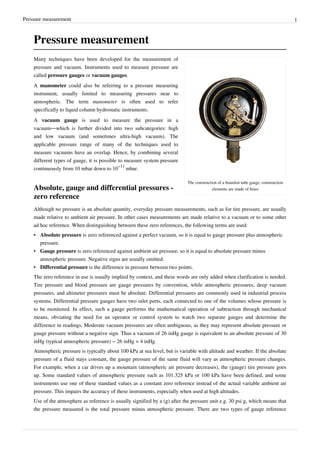
  • 1. Pressure measurement 1 Pressure measurement The construction of a bourdon tube gauge, construction elements are made of brass Many techniques have been developed for the measurement of pressure and vacuum. Instruments used to measure pressure are called pressure gauges or vacuum gauges. A manometer could also be referring to a pressure measuring instrument, usually limited to measuring pressures near to atmospheric. The term manometer is often used to refer specifically to liquid column hydrostatic instruments. A vacuum gauge is used to measure the pressure in a vacuum—which is further divided into two subcategories: high and low vacuum (and sometimes ultra-high vacuum). The applicable pressure range of many of the techniques used to measure vacuums have an overlap. Hence, by combining several different types of gauge, it is possible to measure system pressure continuously from 10 mbar down to 10 −11 mbar. Absolute, gauge and differential pressures - zero reference Although no pressure is an absolute quantity, everyday pressure measurements, such as for tire pressure, are usually made relative to ambient air pressure. In other cases measurements are made relative to a vacuum or to some other ad hoc reference. When distinguishing between these zero references, the following terms are used: • Absolute pressure is zero referenced against a perfect vacuum, so it is equal to gauge pressure plus atmospheric pressure. • Gauge pressure is zero referenced against ambient air pressure, so it is equal to absolute pressure minus atmospheric pressure. Negative signs are usually omitted. • Differential pressure is the difference in pressure between two points. The zero reference in use is usually implied by context, and these words are only added when clarification is needed. Tire pressure and blood pressure are gauge pressures by convention, while atmospheric pressures, deep vacuum pressures, and altimeter pressures must be absolute. Differential pressures are commonly used in industrial process systems. Differential pressure gauges have two inlet ports, each connected to one of the volumes whose pressure is to be monitored. In effect, such a gauge performs the mathematical operation of subtraction through mechanical means, obviating the need for an operator or control system to watch two separate gauges and determine the difference in readings. Moderate vacuum pressures are often ambiguous, as they may represent absolute pressure or gauge pressure without a negative sign. Thus a vacuum of 26 inHg gauge is equivalent to an absolute pressure of 30 inHg (typical atmospheric pressure) − 26 inHg = 4 inHg. Atmospheric pressure is typically about 100 kPa at sea level, but is variable with altitude and weather. If the absolute pressure of a fluid stays constant, the gauge pressure of the same fluid will vary as atmospheric pressure changes. For example, when a car drives up a mountain (atmospheric air pressure decreases), the (gauge) tire pressure goes up. Some standard values of atmospheric pressure such as 101.325 kPa or 100 kPa have been defined, and some instruments use one of these standard values as a constant zero reference instead of the actual variable ambient air pressure. This impairs the accuracy of these instruments, especially when used at high altitudes. Use of the atmosphere as reference is usually signified by a (g) after the pressure unit e.g. 30 psi g, which means that the pressure measured is the total pressure minus atmospheric pressure. There are two types of gauge reference
  • 2. Pressure measurement 2 pressure: vented gauge (vg) and sealed gauge (sg). A vented gauge pressure transmitter for example allows the outside air pressure to be exposed to the negative side of the pressure sensing diaphragm, via a vented cable or a hole on the side of the device, so that it always measures the pressure referred to ambient barometric pressure. Thus a vented gauge reference pressure sensor should always read zero pressure when the process pressure connection is held open to the air. A sealed gauge reference is very similar except that atmospheric pressure is sealed on the negative side of the diaphragm. This is usually adopted on high pressure ranges such as hydraulics where atmospheric pressure changes will have a negligible effect on the accuracy of the reading, so venting is not necessary. This also allows some manufacturers to provide secondary pressure containment as an extra precaution for pressure equipment safety if the burst pressure of the primary pressure sensing diaphragm is exceeded. There is another way of creating a sealed gauge reference and this is to seal a high vacuum on the reverse side of the sensing diaphragm. Then the output signal is offset so the pressure sensor reads close to zero when measuring atmospheric pressure. A sealed gauge reference pressure transducer will never read exactly zero because atmospheric pressure is always changing and the reference in this case is fixed at 1 bar. An absolute pressure measurement is one that is referred to absolute vacuum. The best example of an absolute referenced pressure is atmospheric or barometric pressure. To produce an absolute pressure sensor the manufacturer will seal a high vacuum behind the sensing diaphragm. If the process pressure connection of an absolute pressure transmitter is open to the air, it will read the actual barometric pressure. Units Pressure units Pascal (Pa) Bar (bar) Technical atmosphere (at) Atmosphere (atm) Torr (Torr) Pound-force per square inch (psi) 1 Pa ≡ 1 N/m 2 10 −5 1.0197×10 −5 9.8692×10 −6 7.5006×10 −3 145.04×10 −6 1 bar 100,000 ≡ 10 6  dyn/cm 2 1.0197 0.98692 750.06 14.5037744 1 at 98,066.5 0.980665 ≡ 1 kgf/cm 2 0.96784 735.56 14.223 1 atm 101,325 1.01325 1.0332 ≡ 1 atm 760 14.696 1 torr 133.322 1.3332×10 −3 1.3595×10 −3 1.3158×10 −3 ≡ 1 Torr; ≈ 1 mmHg 19.337×10 −3 1 psi 6.894×10 3 68.948×10 −3 70.307×10 −3 68.046×10 −3 51.715 ≡ 1 lbf/in 2 Example reading: 1 Pa = 1 N/m 2  = 10 −5 bar  = 10.197×10 −6 at  = 9.8692×10 −6 atm  = 7.5006×10 −3 torr  = 145.04×10 −6 psi etc. The SI unit for pressure is the pascal (Pa), equal to one newton per square metre (N·m −2 or kg·m −1 ·s −2 ). This special name for the unit was added in 1971; before that, pressure in SI was expressed in units such as N/m². When indicated, the zero reference is stated in parenthesis following the unit, for example 101 kPa (abs). The pound per square inch (psi) is still in widespread use in the US and Canada, notably for cars. A letter is often appended to the psi unit to indicate the measurement's zero reference; psia for absolute, psig for gauge, psid for differential, although
  • 3. Pressure measurement 3 this practice is discouraged by the NIST. [1] Because pressure was once commonly measured by its ability to displace a column of liquid in a manometer, pressures are often expressed as a depth of a particular fluid (e.g. inches of water). The most common choices are mercury (Hg) and water; water is nontoxic and readily available, while mercury's density allows for a shorter column (and so a smaller manometer) to measure a given pressure. Fluid density and local gravity can vary from one reading to another depending on local factors, so the height of a fluid column does not define pressure precisely. When 'millimetres of mercury' or 'inches of mercury' are quoted today, these units are not based on a physical column of mercury; rather, they have been given precise definitions that can be expressed in terms of SI units. The water-based units usually assume one of the older definitions of the kilogram as the weight of a litre of water. Although no longer favoured by measurement experts, these manometric units are still encountered in many fields. Blood pressure is measured in millimetres of mercury in most of the world, and lung pressures in centimeters of water are still common. Natural gas pipeline pressures are measured in inches of water, expressed as '"WC' ('Water Column'). Scuba divers often use a manometric rule of thumb: the pressure exerted by ten metres depth of water is approximately equal to one atmosphere. In vacuum systems, the units torr, micrometre of mercury (micron), and inch of mercury (inHg) are most commonly used. Torr and micron usually indicates an absolute pressure, while inHg usually indicates a gauge pressure. Atmospheric pressures are usually stated using kilopascal (kPa), or atmospheres (atm), except in American meteorology where the hectopascal (hPa) and millibar (mbar) are preferred. In American and Canadian engineering, stress is often measured in kip. Note that stress is not a true pressure since it is not scalar. In the cgs system the unit of pressure was the barye (ba), equal to 1 dyn·cm −2 . In the mts system, the unit of pressure was the pieze, equal to 1 sthene per square metre. Many other hybrid units are used such as mmHg/cm² or grams-force/cm² (sometimes as kg/cm² and g/mol2 without properly identifying the force units). Using the names kilogram, gram, kilogram-force, or gram-force (or their symbols) as a unit of force is forbidden in SI; the unit of force in SI is the newton (N). Static and dynamic pressure Static pressure is uniform in all directions, so pressure measurements are independent of direction in an immovable (static) fluid. Flow, however, applies additional pressure on surfaces perpendicular to the flow direction, while having little impact on surfaces parallel to the flow direction. This directional component of pressure in a moving (dynamic) fluid is called dynamic pressure. An instrument facing the flow direction measures the sum of the static and dynamic pressures; this measurement is called the total pressure or stagnation pressure. Since dynamic pressure is referenced to static pressure, it is neither gauge nor absolute; it is a differential pressure. While static gauge pressure is of primary importance to determining net loads on pipe walls, dynamic pressure is used to measure flow rates and airspeed. Dynamic pressure can be measured by taking the differential pressure between instruments parallel and perpendicular to the flow. Pitot-static tubes, for example perform this measurement on airplanes to determine airspeed. The presence of the measuring instrument inevitably acts to divert flow and create turbulence, so its shape is critical to accuracy and the calibration curves are often non-linear.
  • 4. Pressure measurement 4 Applications • Altimeter • Barometer • MAP sensor • Pitot tube • Sphygmomanometer Instruments Many instruments have been invented to measure pressure, with different advantages and disadvantages. Pressure range, sensitivity, dynamic response and cost all vary by several orders of magnitude from one instrument design to the next. The oldest type is the liquid column (a vertical tube filled with mercury) manometer invented by Evangelista Torricelli in 1643. The U-Tube was invented by Christian Huygens in 1661. Hydrostatic Hydrostatic gauges (such as the mercury column manometer) compare pressure to the hydrostatic force per unit area at the base of a column of fluid. Hydrostatic gauge measurements are independent of the type of gas being measured, and can be designed to have a very linear calibration. They have poor dynamic response.
  • 5. Pressure measurement 5 Piston Piston-type gauges counterbalance the pressure of a fluid with a solid weight or a spring. Another name for piston gauge is deadweight tester. For example, dead-weight testers used for calibration or tire-pressure gauges. Liquid column The difference in fluid height in a liquid column manometer is proportional to the pressure difference. Liquid column gauges consist of a vertical column of liquid in a tube whose ends are exposed to different pressures. The column will rise or fall until its weight is in equilibrium with the pressure differential between the two ends of the tube. A very simple version is a U-shaped tube half-full of liquid, one side of which is connected to the region of interest while the reference pressure (which might be the atmospheric pressure or a vacuum) is applied to the other. The difference in liquid level represents the applied pressure. The pressure exerted by a column of fluid of height h and density ρ is given by the hydrostatic pressure equation, P = hgρ. Therefore the pressure difference between the applied pressure P a and the reference pressure P 0 in a U-tube manometer can be found by solving P a − P 0 = hgρ. In other words, the pressure on either end of the liquid (shown in blue in the figure to the right) must be balanced (since the liquid is static) and so P a = P 0 + hgρ. If the fluid being measured is significantly dense, hydrostatic corrections may have to be made for the height between the moving surface of the manometer working fluid and the location where the pressure measurement is desired. Although any fluid can be used, mercury is preferred for its high density (13.534 g/cm 3 ) and low vapour pressure. For low pressure differences well above the vapour pressure of water, water is commonly used (and "inches of water" is a common pressure unit). Liquid-column pressure gauges are independent of the type of gas being measured and have a highly linear calibration. They have poor dynamic response. When measuring vacuum, the working liquid may evaporate and contaminate the vacuum if its vapor pressure is too high. When measuring liquid pressure, a loop filled with gas or a light fluid must isolate the liquids to prevent them from mixing. Simple hydrostatic gauges can measure pressures ranging from a few Torr (a few 100 Pa) to a few atmospheres. (Approximately 1,000,000 Pa) A single-limb liquid-column manometer has a larger reservoir instead of one side of the U-tube and has a scale beside the narrower column. The column may be inclined to further amplify the liquid movement. Based on the use and structure following type of manometers are used [2] 1. Simple Manometer 2. Micromanometer 3. Differential manometer 4. Inverted differential manometer
  • 6. Pressure measurement 6 A McLeod gauge, drained of mercury McLeod gauge A McLeod gauge isolates a sample of gas and compresses it in a modified mercury manometer until the pressure is a few mmHg. The gas must be well-behaved during its compression (it must not condense, for example). The technique is slow and unsuited to continual monitoring, but is capable of good accuracy. Useful range: above 10 -4 torr [3] (roughly 10 -2 Pa) as high as 10 −6  Torr (0.1 mPa), 0.1 mPa is the lowest direct measurement of pressure that is possible with current technology. Other vacuum gauges can measure lower pressures, but only indirectly by measurement of other pressure-controlled properties. These indirect measurements must be calibrated to SI units via a direct measurement, most commonly a McLeod gauge. [4] Aneroid Aneroid gauges are based on a metallic pressure sensing element which flexes elastically under the effect of a pressure difference across the element. "Aneroid" means "without fluid," and the term originally distinguished these gauges from the hydrostatic gauges described above. However, aneroid gauges can be used to measure the pressure of a liquid as well as a gas, and they are not the only type of gauge that can operate without fluid. For this reason, they are often called mechanical gauges in modern language. Aneroid gauges are not dependent on the type of gas being measured, unlike thermal and ionization gauges, and are less likely to contaminate the system than hydrostatic gauges. The pressure sensing element may be a Bourdon tube, a diaphragm, a capsule, or a set of bellows, which will change shape in response to the pressure of the region in question. The deflection of the pressure sensing element may be read by a linkage connected to a needle, or it may be read by a secondary transducer. The most common secondary transducers in modern vacuum gauges measure a change in capacitance due to the mechanical deflection. Gauges that rely on a change in capacitances are often referred to as Baratron gauges. Bourdon Membrane-type manometer The Bourdon pressure gauge uses the principle that a flattened tube tends to change to a more circular cross-section when pressurized. Although this change in cross-section may be hardly noticeable, and thus involving moderate stresses within the elastic range of easily workable materials, the strain of the material of the tube is magnified by forming the tube into a C shape or even a helix, such that the entire tube tends to straighten out or uncoil, elastically, as it is pressurized. Eugene Bourdon patented his gauge in France in 1849, and it was widely adopted because of its superior sensitivity, linearity, and accuracy; Edward Ashcroft
  • 7. Pressure measurement 7 purchased Bourdon's American patent rights in 1852 and became a major manufacturer of gauges. Also in 1849, Bernard Schaeffer in Magdeburg, Germany patented a successful diaphragm (see below) pressure gauge, which together with the Bourdon gauge, revolutionized pressure measurement in industry. [5] But in 1875 after Bourdon's patents expired, his company Schaeffer and Budenberg also manufactured Bourdon tube gauges. In practice, a flattened thin-wall, closed-end tube is connected at the hollow end to a fixed pipe containing the fluid pressure to be measured. As the pressure increases, the closed end moves in an arc, and this motion is converted into the rotation of a (segment of a) gear by a connecting link which is usually adjustable. A small diameter pinion gear is on the pointer shaft, so the motion is magnified further by the gear ratio. The positioning of the indicator card behind the pointer, the initial pointer shaft position, the linkage length and initial position, all provide means to calibrate the pointer to indicate the desired range of pressure for variations in the behaviour of the Bourdon tube itself. Differential pressure can be measured by gauges containing two different Bourdon tubes, with connecting linkages. Bourdon tubes measure gauge pressure, relative to ambient atmospheric pressure, as opposed to absolute pressure; vacuum is sensed as a reverse motion. Some aneroid barometers use Bourdon tubes closed at both ends (but most use diaphragms or capsules, see below). When the measured pressure is rapidly pulsing, such as when the gauge is near a reprocating pump, an orfice restriction in the connecting pipe is frequently used to avoid unnecessary wear on the gears and provide an average reading; when the whole gauge is subject to mechanical vibration, the entire case including the pointer and indicator card can be filled with an oil or glycerin. Typical high-quality modern gauges provide an accuracy of ±2% of span, and a special high-precision gauge can be as accurate as 0.1% of full scale. [6] In the following illustrations the transparent cover face of the pictured combination pressure and vacuum gauge has been removed and the mechanism removed from the case. This particular gauge is a combination vacuum and pressure gauge used for automotive diagnosis: Indicator side with card and dial • the left side of the face, used for measuring manifold vacuum, is calibrated in centimetres of mercury on its inner scale and inches of mercury on its outer scale. • the right portion of the face is used to measure fuel pump pressure and is calibrated in fractions of 1 kgf/cm² on its inner scale and pounds per square inch on its outer scale.
  • 8. Pressure measurement 8 Mechanical side with Bourdon tube Mechanical details Mechanical details Stationary parts: • A: Receiver block. This joins the inlet pipe to the fixed end of the Bourdon tube (1) and secures the chassis plate (B). The two holes receive screws that secure the case. • B: Chassis plate. The face card is attached to this. It contains bearing holes for the axles. • C: Secondary chassis plate. It supports the outer ends of the axles. • D: Posts to join and space the two chassis plates. Moving Parts: 1. Stationary end of Bourdon tube. This communicates with the inlet pipe through the receiver block. 2. Moving end of Bourdon tube. This end is sealed. 3. Pivot and pivot pin. 4. Link joining pivot pin to lever (5) with pins to allow joint rotation. 5. Lever. This an extension of the sector gear (7). 6. Sector gear axle pin. 7. Sector gear. 8. Indicator needle axle. This has a spur gear that engages the sector gear (7) and extends through the face to drive the indicator needle. Due to the short distance between the lever arm link boss and the pivot pin and the difference between the effective radius of the sector gear and that of the spur gear, any motion of the Bourdon tube is greatly amplified. A small motion of the tube results in a large motion of the indicator needle. 9. Hair spring to preload the gear train to eliminate gear lash and hysteresis.
  • 9. Pressure measurement 9 Diaphragm A pile of pressure capsules with corrugated diaphragms in an aneroid barograph. A second type of aneroid gauge uses the deflection of a flexible membrane that separates regions of different pressure. The amount of deflection is repeatable for known pressures so the pressure can be determined by using calibration. The deformation of a thin diaphragm is dependent on the difference in pressure between its two faces. The reference face can be open to atmosphere to measure gauge pressure, open to a second port to measure differential pressure, or can be sealed against a vacuum or other fixed reference pressure to measure absolute pressure. The deformation can be measured using mechanical, optical or capacitive techniques. Ceramic and metallic diaphragms are used. Useful range: above 10 -2 Torr [7] (roughly 1 Pa) For absolute measurements, welded pressure capsules with diaphragms on either side are often used. Shape: • Flat • corrugated • flattened tube • capsule Bellows In gauges intended to sense small pressures or pressure differences, or require that an absolute pressure be measured, the gear train and needle may be driven by an enclosed and sealed bellows chamber, called an aneroid, which means "without liquid". (Early barometers used a column of liquid such as water or the liquid metal mercury suspended by a vacuum.) This bellows configuration is used in aneroid barometers (barometers with an indicating needle and dial card), altimeters, altitude recording barographs, and the altitude telemetry instruments used in weather balloon radiosondes. These devices use the sealed chamber as a reference pressure and are driven by the external pressure. Other sensitive aircraft instruments such as air speed indicators and rate of climb indicators (variometers) have connections both to the internal part of the aneroid chamber and to an external enclosing chamber. Electronic pressure sensors • Piezoresistive Strain Gage Uses the piezoresistive effect of bonded or formed strain gauges to detect strain due to applied pressure. • Capacitive Uses a diaphragm and pressure cavity to create a variable capacitor to detect strain due to applied pressure. • Magnetic Measures the displacement of a diaphragm by means of changes in inductance (reluctance), LVDT, Hall Effect, or by eddy current principal. • Piezoelectric Uses the piezoelectric effect in certain materials such as quartz to measure the strain upon the sensing mechanism due to pressure.
  • 10. Pressure measurement 10 • Optical Uses the physical change of an optical fiber to detect strain due applied pressure. • Potentiometric Uses the motion of a wiper along a resistive mechanism to detect the strain caused by applied pressure. • Resonant Uses the changes in resonant frequency in a sensing mechanism to measure stress, or changes in gas density, caused by applied pressure. Thermal conductivity Generally, as a real gas increases in density -which may indicate an increase in pressure- its ability to conduct heat increases. In this type of gauge, a wire filament is heated by running current through it. A thermocouple or Resistance Temperature Detector (RTD) can then be used to measure the temperature of the filament. This temperature is dependent on the rate at which the filament loses heat to the surrounding gas, and therefore on the thermal conductivity. A common variant is the Pirani gauge which uses a single platinum filament as both the heated element and RTD. These gauges are accurate from 10 Torr to 10 −3  Torr, but they are sensitive to the chemical composition of the gases being measured. Two wire One wire coil is used as a heater, and the other is used to measure nearby temperature due to convection. Pirani (one wire) A Pirani gauge consists of a metal wire open to the pressure being measured. The wire is heated by a current flowing through it and cooled by the gas surrounding it. If the gas pressure is reduced, the cooling effect will decrease, hence the equilibrium temperature of the wire will increase. The resistance of the wire is a function of its temperature: by measuring the voltage across the wire and the current flowing through it, the resistance (and so the gas pressure) can be determined. This type of gauge was invented by Marcello Pirani. Thermocouple gauges and thermistor gauges work in a similar manner, except a thermocouple or thermistor is used to measure the temperature of the wire. Useful range: 10 -3 - 10 Torr [8] (roughly 10 -1 - 1000 Pa) Ionization gauge Ionization gauges are the most sensitive gauges for very low pressures (also referred to as hard or high vacuum). They sense pressure indirectly by measuring the electrical ions produced when the gas is bombarded with electrons. Fewer ions will be produced by lower density gases. The calibration of an ion gauge is unstable and dependent on the nature of the gases being measured, which is not always known. They can be calibrated against a McLeod gauge which is much more stable and independent of gas chemistry. Thermionic emission generate electrons, which collide with gas atoms and generate positive ions. The ions are attracted to a suitably biased electrode known as the collector. The current in the collector is proportional to the rate of ionization, which is a function of the pressure in the system. Hence, measuring the collector current gives the gas pressure. There are several sub-types of ionization gauge. Useful range: 10 -10 - 10 -3 torr (roughly 10 -8 - 10 -1 Pa) Most ion gauges come in two types: hot cathode and cold cathode, a third type exists which is more sensitive and expensive known as a spinning rotor gauge, but is not discussed here. In the hot cathode version an electrically heated filament produces an electron beam. The electrons travel through the gauge and ionize gas molecules around them. The resulting ions are collected at a negative electrode. The current depends on the number of ions, which
  • 11. Pressure measurement 11 depends on the pressure in the gauge. Hot cathode gauges are accurate from 10 −3  Torr to 10 −10  Torr. The principle behind cold cathode version is the same, except that electrons are produced in the discharge of a high voltage. Cold Cathode gauges are accurate from 10 −2  Torr to 10 −9  Torr. Ionization gauge calibration is very sensitive to construction geometry, chemical composition of gases being measured, corrosion and surface deposits. Their calibration can be invalidated by activation at atmospheric pressure or low vacuum. The composition of gases at high vacuums will usually be unpredictable, so a mass spectrometer must be used in conjunction with the ionization gauge for accurate measurement. [9] Hot cathode Bayard-Alpert hot cathode ionization gauge A hot cathode ionization gauge is mainly composed of three electrodes acting together as a triode, where the cathode is the filament. The three electrodes are a collector or plate, a filament, and a grid. The collector current is measured in picoamps by an electrometer. The filament voltage to ground is usually at a potential of 30 volts while the grid voltage at 180–210 volts DC, unless there is an optional electron bombardment feature, by heating the grid which may have a high potential of approximately 565 volts. The most common ion gauge is the hot cathode Bayard-Alpert gauge, with a small ion collector inside the grid. A glass envelope with an opening to the vacuum can surround the electrodes, but usually the Nude Gauge is inserted in the vacuum chamber directly, the pins being fed through a ceramic plate in the wall of the chamber. Hot cathode gauges can be damaged or lose their calibration if they are exposed to atmospheric pressure or even low vacuum while hot. The measurements of a hot cathode ionization gauge are always logarithmic. Electrons emitted from the filament move several times in back and forth movements around the grid before finally entering the grid. During these movements, some electrons collide with a gaseous molecule to form a pair of an ion and an electron (Electron ionization). The number of these ions is proportional to the gaseous molecule density multiplied by the electron current emitted from the filament, and these ions pour into the collector to form an ion current. Since the gaseous molecule density is proportional to the pressure, the pressure is estimated by measuring the ion current. The low pressure sensitivity of hot cathode gauges is limited by the photoelectric effect. Electrons hitting the grid produce x-rays that produce photoelectric noise in the ion collector. This limits the range of older hot cathode gauges to 10 −8 Torr and the Bayard-Alpert to about 10 −10 Torr. Additional wires at cathode potential in the line of sight between the ion collector and the grid prevent this effect. In the extraction type the ions are not attracted by a wire, but by an open cone. As the ions cannot decide which part of the cone to hit, they pass through the hole and form an ion beam. This ion beam can be passed on to a • Faraday cup • Microchannel plate detector with Faraday cup • Quadrupole mass analyzer with Faraday cup • Quadrupole mass analyzer with Microchannel plate detector Faraday cup • ion lens and acceleration voltage and directed at a target to form a sputter gun. In this case a valve lets gas into the grid-cage.
  • 12. Pressure measurement 12 Cold cathode There are two subtypes of cold cathode ionization gauges: the Penning gauge (invented by Frans Michel Penning), and the Inverted magnetron, also called a Redhead gauge. The major difference between the two is the position of the anode with respect to the cathode. Neither has a filament, and each may require a DC potential of about 4 kV for operation. Inverted magnetrons can measure down to 1x10 −12 Torr. Such gauges cannot operate if the ions generated by the cathode recombine before reaching the anodes. If the mean-free path of the gas within the gauge is smaller than the gauge's dimensions, then the electrode current will essentially vanish. A practical upper-bound to the detectable pressure is, for a Penning gauge, of the order of 10 −3 Torr. Similarly, cold cathode gauges may be reluctant to start at very low pressures, in that the near-absence of a gas makes it difficult to establish an electrode current - particularly in Penning gauges which use an axially symmetric magnetic field to create path lengths for ions which are of the order of metres. In ambient air suitable ion-pairs are ubiquitously formed by cosmic radiation; in a Penning gauge design features are used to ease the set-up of a discharge path. For example, the electrode of a Penning gauge is usually finely tapered to facilitate the field emission of electrons. Maintenance cycles of cold cathode gauges are generally measured in years, depending on the gas type and pressure that they are operated in. Using a cold cathode gauge in gases with substantial organic components, such as pump oil fractions, can result in the growth of delicate carbon films and shards within the gauge which eventually either short-circuit the electrodes of the gauge, or impede the generation of a discharge path. Calibration Pressure gauges are either direct- or indirect-reading. Hydrostatic and elastic gauges measure pressure are directly influenced by force exerted on the surface by incident particle flux, and are called direct reading gauges. Thermal and ionization gauges read pressure indirectly by measuring a gas property that changes in a predictable manner with gas density. Indirect measurements are susceptible to more errors than direct measurements. • Dead weight tester • McLeod • mass spec + ionization Dynamic transients When fluid flows are not in equilibrium, local pressures may be higher or lower than the average pressure in a medium. These disturbances propagate from their source as longitudinal pressure variations along the path of propagation. This is also called sound. Sound pressure is the instantaneous local pressure deviation from the average pressure caused by a sound wave. Sound pressure can be measured using a microphone in air and a hydrophone in water. The effective sound pressure is the root mean square of the instantaneous sound pressure over a given interval of time. Sound pressures are normally small and are often expressed in units of microbar. • frequency response of pressure sensors • resonance
  • 13. Pressure measurement 13 European (CEN) Standard • EN 472 : Pressure gauge - Vocabulary. • EN 837-1 : Pressure gauges. Bourdon tube pressure gauges. Dimensions, metrology, requirements and testing. • EN 837-2 : Pressure gauges. Selection and installation recommendations for pressure gauges. • EN 837-3 : Pressure gauges. Diaphragm and capsule pressure gauges. Dimensions, metrology, requirements and testing.. External links • Home Made Manometer [10] • Manometer [11] References [1] NIST (http://physics.nist.gov/Pubs/SP811/sec07.html#7.4) [2] [Was: "fluidengineering.co.nr/Manometer.htm". At 1/2010 that took me to bad link. Types of fluid Manometers] [3] Techniques of high vacuum (http://www.tau.ac.il/~phchlab/experiments/vacuum/Techniques_of_high_vacuum/Vacuum5.html) [4] Beckwith, Thomas G.; Roy D. Marangoni and John H. Lienhard V (1993). "Measurement of Low Pressures". Mechanical Measurements (Fifth ed.). Reading, MA: Addison-Wesley. pp. 591–595. ISBN 0-201-56947-7. [5] The Engine Indicator Canadian Museum of Making (http://www.archivingindustry.com/Indicator/discspring.htm) [6] Boyes, Walt (2008). Instrumentation Reference Book, Fourth Edition. Butterworth-Heinemann. pp. 1312. [7] Product brochure from Schoonover, Inc (http://www.schoonoverinc.com/PDFs/Sky Brochure.pdf) [8] VG Scienta (http://www.vacgen.com/asp/catalogue.asp?url=http://www.vacgen.com/catalogue/section-8/page08_03.htm&frame=1) [9] Robert M. Besançon, ed (1990). "Vacuum Techniques" (3rd ed.). Van Nostrand Reinhold, New York. pp. 1278–1284. ISBN 0-442-00522-9. [10] http://www.komar.org/faq/manometer/ [11] http://www.upscale.utoronto.ca/PVB/Harrison/Manometer/Manometer.html
  • 14. Article Sources and Contributors 14 Article Sources and Contributors Pressure measurement  Source: http://en.wikipedia.org/w/index.php?oldid=421302664  Contributors: A. Carty, AFreyler, Abc12344, Abustek, Achalmeena, Ahtih, Alansohn, Ale jrb, Alex.muller, Alex.tan, Androstachys, Anonymous anonymous, Apers0n, Arc de Ciel, ArglebargleIV, Atlant, Audriusa, BAICAN XXX, BD2412, Bemoeial, Bobo192, Boringbob4wk, Cacycle, Chris G, Congruence, Conscious, Conversion script, Coolkunal64, Crystal whacker, DVdm, Darkstar78, DeadEyeArrow, Deathreap, Diannaa, Dicklyon, Dimotika, Dlrohrer2003, Dto, Dual Freq, Eequor, Excirial, Finejon, Flewis, Fram, Fratrep, Fuhghettaboutit, Gawaxay, Gene Nygaard, Geniuz rulez, Giuliopp, Glenn, Gnowor, H Padleckas, HBR10, Heron, Hooperbloob, Ideapostpaidmobile, J-puppy, J04n, Ja 62, James086, Janke, Jef-Infojef, Jimp, Johny1230456789, Jojalozzo, JorisvS, Joseph Solis in Australia, Julo, Kkmurray, Leonard G., LilHelpa, Lisatwo, M3tainfo, Mark.murphy, Markus Kuhn, Matthil, Mbeychok, Mcguireatneuroticadotcom, Michael Hardy, Mike Dill, Mion, Moony99, Mr Stephen, Msauve, NHRHS2010, Nate Silva, NawlinWiki, NebY, Nibha2005, Nposs, NuclearWarfare, Nynicks00, Nyr56, Orhannina, Pabix, Peter Horn, Piano non troppo, Preslethe, Pèlerin Gris, Quantockgoblin, Radiojon, Redvers, Reedy, Rich Farmbrough, Rjstott, Romary, Sam Blacketer, Scallop7, Scwerllguy, Shoefly, Smack, Sophus Bie, Sourpearpirate, SpaceFlight89, Spinningspark, Stefano85, Stewartusa, Storm Rider, StradivariusTV, Svick, Tabletop, Tannkremen, The Thing That Should Not Be, Thorwald, Tkbwik, Trelvis, Ufwuct, User A1, Vrenator, WatchAndObserve, Wayne Slam, WingkeeLEE, Wtshymanski, Wælgæst wæfre, Yegor Chernyshev, Ytrottier, Yyy, Zereshk, Zhou Yu, Zoicon5, Камень, 229 anonymous edits Image Sources, Licenses and Contributors Image:Manometer inside.jpg  Source: http://en.wikipedia.org/w/index.php?title=File:Manometer_inside.jpg  License: GNU Free Documentation License  Contributors: Original uploader was Yegor Chernyshev at en.wikipedia Image:Utube.PNG  Source: http://en.wikipedia.org/w/index.php?title=File:Utube.PNG  License: Creative Commons Attribution-Sharealike 2.5  Contributors: Ruben Castelnuovo (Ub) Image:McLeod gauge.jpg  Source: http://en.wikipedia.org/w/index.php?title=File:McLeod_gauge.jpg  License: Creative Commons Attribution 2.5  Contributors: Editor at Large, El., WikipediaMaster, Ytrottier, 3 anonymous edits Image:Manometer 104026.jpg  Source: http://en.wikipedia.org/w/index.php?title=File:Manometer_104026.jpg  License: GNU Free Documentation License  Contributors: User:Zaphod Image:WPGaugeFace.jpg  Source: http://en.wikipedia.org/w/index.php?title=File:WPGaugeFace.jpg  License: GNU Free Documentation License  Contributors: Roomba, Saperaud, WikipediaMaster, Wst Image:WPPressGaugeMech.jpg  Source: http://en.wikipedia.org/w/index.php?title=File:WPPressGaugeMech.jpg  License: GNU Free Documentation License  Contributors: Saperaud, WikipediaMaster Image:WPPressGaugeDetailHC.jpg  Source: http://en.wikipedia.org/w/index.php?title=File:WPPressGaugeDetailHC.jpg  License: GNU Free Documentation License  Contributors: Christophe.Finot, Leonard G., Saperaud, 1 anonymous edits Image:Barograph 03.jpg  Source: http://en.wikipedia.org/w/index.php?title=File:Barograph_03.jpg  License: GNU Free Documentation License  Contributors: Christophe.Finot, Saperaud Image:Bayard-Alpert gauge.jpg  Source: http://en.wikipedia.org/w/index.php?title=File:Bayard-Alpert_gauge.jpg  License: Creative Commons Attribution-Sharealike 2.5  Contributors: User:Kkmurray License Creative Commons Attribution-Share Alike 3.0 Unported http://creativecommons.org/licenses/by-sa/3.0/