Acoustic emission characterization on composite materials by dr.mohamed bak kamaludeen presentation crescent university
•
0 gefällt mir•52 views

To understand the failure modes on composite lap joints using Acoustic Emission Testing

Empfohlen
Weitere ähnliche Inhalte
Was ist angesagt?
Was ist angesagt? (20)
Ähnlich wie Acoustic emission characterization on composite materials by dr.mohamed bak kamaludeen presentation crescent university
Ähnlich wie Acoustic emission characterization on composite materials by dr.mohamed bak kamaludeen presentation crescent university (20)
Kürzlich hochgeladen
Kürzlich hochgeladen (20)
Acoustic emission characterization on composite materials by dr.mohamed bak kamaludeen presentation crescent university
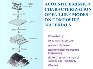
- 1. ACOUSTIC EMISSION CHARACTERIZATION OF FAILURE MODES ON COMPOSITE MATERIALS Presented By Dr. K.MOHAMED BAK Assistant Professor Department of Mechanical Engineering BSAR Crescent Institute of Science and Technology Chennai
- 2. • INTRODUCTION • AIM AND OBJECTIVE • NEED FOR THE STUDY (FLOW CHART) • SPECIMEN PREPARATION • EXPERIMENTAL WORK • MECHANICAL CHARACTERIZATION OF COMPOSITE MATERIALS • ACOUSTIC EMISSION PROCEDURE • AE APPLICATIONS • AE CHARACTERIZATION OF SINGLE LAP JOINTS IN FRP LAMINATE • SUMMARY • REFERENCE
- 3. COMPOSITES IN AEROSPACE Boeing 787 Dreamliner Composite Profile Airbus A380 Composite Profile
- 5. LAMINATION PROCEDURE • A layer of Resin is applied with a brush on the gel coat which has already gelled or cured. • The cut glass fiber mat is placed over the resin • By a stippling action using Resin wetted Brush; the resin is squeezed to the top surface. Care should be taken to see that the required glass-to-resin ratio is uniformly obtained. • Using metal roller the layer is consolidated and the air bubbles removed. It is important that all the air entrapped in the first layer is removed. Otherwise, the air entrapped between gel coat and first layer of mat will expand later causing blistering. • After the first layer is laid up, subsequent layers are laid up in a similar manner. • The procedure has been repeated till the required thickness has been built up.
- 6. Overall aims of this work are to develop an understanding of the mechanical behavior of composite materials (FRP). Acoustic Emission (AE) response in adhesive- bonded lap joints in Glass fiber reinforced plastics (GFRP) and Basalt fiber reinforced plastics (BFRP) laminates. Discuss how it is used as a basis to identify the AE waveforms pertaining to the failure modes. To discriminate the failure modes on lap joints of glass- fiber reinforced plastic (GFRP) and basalt-fiber reinforced plastic (BFRP) laminates and the role of composite structural design in the joint strength. 6
- 7. To design structural components, a deep understanding about material behavior and its failure mechanisms is necessary. Characterization of failure modes in the case of composite lap joints is a complex research subject (Matsuzaki et al 2008). It is suggested that the application of basalt/epoxy laminate as a strengthening material is useful for joining of composite structural members. 7
- 8. PREPARATION OF GLASS FIBER REINFORCED PLASTICS (GFRP) AND BASALT FIBER REINFORCED PLASTICS (BFRP) LAMINATES USING HAND LAY UP PROCESS MATERIAL SELECTION E-GLASS FIBER BASALT FIBER SINGLE LAP JOINTS 1. TENSILE TEST AS PER ASTM D638 STANDARD 2. FLEXURAL TEST SPECIMEN ASTM D790 STANDARD 3. IMPACT TEST SPECIMEN ASTM D5628 STANDARD MECHANICAL CHARCTERIZATION –GFRP and BFRP SUMMARY OF MECHANICAL CHARCTERIZATION 1 STRESS-STRAIN DATA 2. FLEXURAL STRENGTH DATA 3. IMPACT ENERGY DATA 1. ADHESIVE JOINTS (BONDED) AE TEST UNDER TENSILE LOADING 1 PARAMETRIC ANALYSIS OF AE DATA 2 FREQUENCY ANALYSIS OF AE DATA (FAST FOURIER TRANSFORM) IDENTIFICATION OF FAILURE MODES SCANNING ELECTRON MICROSCOPY ANALYSIS A
- 9. A FINITE ELEMENT ANALYSIS (ANSYS) PRE-PROCESSOR SOLVER POST PROCESSOR 9 STRESS Vs DISPLACEMENT VALUE COMPARISION BETWEEN LAP JOINTS OF GFRP, BFRP CONCLUSION SUMMARY OF FAILURE MODES ON SINGLE LAP JOINTS B
- 10. ASTM D 3039 standard tensile specimen - GFRP ASTM D3039 standard tensile specimen - BFRP 10 60mm 180mm ASTM D790 standards flexural test specimen (a) GFRP (b) BFRP a b
- 11. Photographical images of single lap joints as per ASTM 5868 and 3528 Standards (a) GFRP (b) BFRP
- 12. 12
- 13. (a) Tensile test setup (b) flexural test setup 13 Magnifying Lens (a) (b)
- 14. 14 CEAST Fractovis Drop Weight Impact Testing Machine
- 15. MECHANICAL CHARACTERIZATION OF COMPOSITE LAMINATE
- 16. (a) (b) (b) Fractured tensile test specimens (a) GFRP (ASTM D 638) (b) BFRP (ASTM 3039) 16 (a) (b) Stress-strain behavior of tensile test specimens: (a) GFRP (b) BFRP
- 17. Strength Material GFRP BFRP Ultimate tensile strength (MPa) 345 ± 10 355 ± 5 Flexural strength (MPa) 195 ± 30 210 ± 20 On the basis of the data presented in Table 4.1, the mechanical behaviors of the two materials were found, and the ultimate tensile strength and flexural strength were obtained through the tensile and flexural mechanical tests.
- 18. FLEXURAL TEST RESULTS AT DIFFERENT TEMPERATURE 18 Flexural Strength of GFRP and BFRP laminate Fractured specimens (a) GFRP (b) BFRP
- 19. IMPACT TEST RESULTS OF BASALT AND GLASS AT DIFFERENT TEMPERATURE 19 Temperature (0c) Vs Impact Energy for GFRP and BFRP laminate
- 20. FAILURE MODES ON COMPOSITE LAMINATE USING SEM Adhesive (Matrix) Failure Fiber Failure Fiber-Matrix Debonding Delamination Failure
- 21. SUMMARY OF MECHANICAL CHARACTERIZATION Based on the test,no significant differences in tensile strengths are found between basalt/epoxy and the glass/epoxy specimens. In contrast to GFRP, BFRP flexural strength reduction is very minimal at higher temperatures. During impact tests at different temperatures, 28% more energy was absorbed by BFRP laminates compared to GFRP laminates. This work confirms the applicability of basalt fiber as a fiber reinforcing material in polymer composites. 21
- 22. Various NDT Techniques • Visual inspection • Acoustic Emission • Ultrasonic testing • Hydrostatic testing • Radiographic testing • Magnetic Particle inspection • Eddy current testing • Helium leak testing.
- 23. ACOUSTIC EMISSION PRINCIPLE Acoustic Emission refers to the generation of transient elastic waves during the rapid release of energy from localized sources within a material when it is stressed. Acoustic Emission Testing is extremely useful in evaluating, monitoring the structural integrity of components. 23 Figure 1.11: Acoustic emission monitoring process
- 24. Why Acoustic Emission AE is a powerful non destructive technique for real time monitoring of damage development in materials and structures which has been used successfully for the identification of damage mechanisms in composite structures under quasi static and dynamic-cycle loading. AE is expected to be a next-generation technique not only to monitor conditions but also for the repair of damaged structures, combined with an active-adaptive technique using the concept of smart materials. AE is considered to be a very promising technique, together with such sensing techniques as optical fiber and shape memory alloy . AE can play a very important roll in monitoring, evaluating and repairing structures
- 25. Advantages of Acoustic Emission Technique Online Testing- Real Time Monitoring. Rapid Inspection. External Stimulus not required (energy is released from within the test object) Whole Structure can be tested with a few sensors Cost Effective. Permanent Recording of Test. Defect Location.
- 26. Applications of AE Structural integrity evaluation Vessels testing (Hot or cryogenic, metallic and FRP spheres) Nuclear components inspection (Valves, steam lines) Corrosion detection Pipeline testing, leak detection Railroads, Bridge monitoring Ageing aircraft evaluation Advanced material testing Rocket motor testing
- 28. AE Inspection of Pressure Vessels
- 29. Why NDT ?
- 30. Figure 3.22: Wave velocity using pencil lead break test (www.ndt.in)
- 31. 31 Standard deviation values of wave velocity for different lap joints ATTENUATION
- 32. Adhesive (Matrix) Failure Fiber Tear Failure Delamination Delamination Matrix Cracking Fiber Failure 32
- 33. From parametric analysis, the literature (Santuli et al 2012) reveals that there are three damage zones such as damage initiation, damage accumulation and unstable damage growth on composite materials during loading. (a) Adhesive failure (b) Light fiber tear failure (c) Fiber tear failure 33
- 35. Characterization of Failure Modes on Adhesive- Bonded Lap Joints (a) Pure Resin Bonded Joints Zone I-Adhesive failure
- 36. Single layer adhesive-bonded lap joints Zone I-Damage initiation (Adhesive failure) Zone II-Damage accumulation (Light fiber tear failure) Zone III-Damage Growth (Fiber tear failure) Figure : Displacement vs AE count rate
- 37. Load Vs Displacement diagram of bonded, riveted and hybrid single lap joints in glass laminate Failure modes observed on single lap joints in GFRP laminate 37 I III II IV Displacement and AE count rate Vs AE Cumulative counts for Single lap joints Single lap joints in Glass laminate
- 38. Displacement and AE count rate Vs AE Cumulative counts for single lap joints Single lap joints in basalt laminate 38 I III II Load Vs Displacement diagram of bonded, riveted and hybrid single lap joints in Basalt laminate Failure modes observed on single lap joints in BFRP laminate
- 39. Standard deviation values of ultimate load and displacement for single lap joints in GFRP and BFRP laminates (Table 4.6) Material Single Lap Joints (SLJ) Ultimate Load (kN) Displacement (mm) Glass/ epoxy Bonded (B) 6 ± 1.5 1. 5 ± 0.25 Basalt/ epoxy Bonded (B) 6 ± 2.0 1.5 ± 0.3 The standard deviation values of displacement and ultimate load of single lap joints in GFRP laminates showed good agreement with results of single lap joints in BFRP laminates as shown in Table 4.6.
- 40. IDENTIFICATION OF FAILURE MODES USING AE TOOL 1.PARAMETRIC ANALYSIS 1.AE cumulative Counts 2. Multi Scale Approach i) FFT Analysis 2.FREQUENCYANALYSIS 3. SEM ANALYSIS 40
- 41. Failure modes on lap joints in GFRP and BFRP are identified using various AE parameters such as cumulative Counts, counts rate, amplitude and duration. The multi-scale approach is used to identify failure modes based on variation of amplitude and duration of the AE events . As AE amplitude parameter suffers from different AE events after preliminary investigations in the parametric analysis, the failure modes are characterized mostly using frequency analysis. PARAMETRIC ANALYSIS 41
- 42. Pure Resin Bonded Joints Peak frequency and Cumulative counts versus time (a) single lap joints 42 a
- 43. FAST FOURIER TRANSFORM (FFT) The second approach is based on the extraction of frequency content from AE waveform with appropriate algorithms. Frequency–based analysis of AE waveforms may be used as a tool to investigate the overlapping nature of the failure modes obtained from parametric analysis. FFT analysis is performed on a number of randomly chosen waveform pertaining to different frequency ranges to identify the frequency content of each failure mode. 29.11.13 43
- 44. Waveform of AE signal converted into FFT frequency plot using MATLAB code (video)
- 45. SEM image representation of the adhesive failure mode in pure resin specimen Typical AE time domain and FFT signal for individual failure mode on pure resin bonded lap joint 45
- 46. (a) (b) AE parametric analysis of (a) peak frequency and cumulative counts versus time (b) Amplitude and duration versus time AE PARAMETRIC ANALYSIS RESULTS Delamination Matrix cracking Fiber- Matrix debonding
- 47. SINGLE AND DOUBLE LAYER OF LAP JOINTS The main problems from an analytical and experimental point of view in AE monitoring are [Garg et al 1983] 1) how to distinguish between the different failures modes 2) how to assess the individual and associated failure modes A sudden increase in AE cumulative counts are observed due to the recording of medium duration hits and high duration hits (Figures 4.24 and 4.25), which are attributed to light-fiber tear failure mode (Zone II) and fiber tear failure (Zone III).
- 48. SINGLE LAYER SPECIMEN (GLOBAL METHOD) Adhesive Failure Light Fiber Tear Failure Adhesive Failure Light Fiber Tear Failure Fiber Tear Failure Fiber Tear Failure frequency and Cumulative counts versus time and location (a) single lap joints (b) Double lap joints 48 20mm
- 49. DOUBLE (TWO) LAYER SPECIMEN Adhesive Failure Light Fiber Tear Failure Fiber Tear Failure Peak frequency and Cumulative counts versus time and Location (a) Single lap joints (b) Double lap joints 49
- 50. Adhesive Failure Light Fiber Tear Failure Fiber Tear Failure Adhesive Failure Light Fiber Tear Failure Glass FR Laminate Basalt FR Laminate Single Lap Bonded Joints Figure 4.36 and 4.72 :Peak frequency and Cumulative counts versus time (a) GFRP(b) BFRP 50
- 51. Light Fiber Tear Failure Adhesive Failure Peak frequency Vs Location for bonded joints Glass FR Laminate Basalt FR Laminate Adhesive Failure Fiber Tear Failure Light Fiber Tear Failure
- 52. Failure modes on single Layer Specimen using FFT and SEM images 52 FFT ANALYSIS RESULTS
- 53. Peak frequency Vs location for lap joints After careful examination of the AE waveforms, it is found that there are three different ranges of characteristic frequencies involved (Ramirez-Jimenez et al 2004). A different AE behavior was noticed where AE counts are detected at the initial stage of loading. A large number of AE waveforms in the time domain (events) are recorded during tensile test and the fiber tear failure was observed at the final stage loading. Adhesive Failure Overlap Region Light Fiber Tear Failure Fiber Tear Failure
- 54. Adhesive Failure (Crack Initiation) Low Amplitude Low Duration Light Fiber Tear failure Moderate Amplitude Moderate Duration Low Frequency Medium Frequency 54 COMPARATIVE OF THE FAILURE MODES USING AE DATA
- 55. Delamination High Amplitude High Duration High Frequency Fiber Tear Failure High Amplitude High Duration High Frequency
- 56. SUMMARY OF FAILURE MODES USING AE DATA The discrimination of failure modes from AE signal parametric analysis to separate the failure modes was largely unsuccessful due to the overlapping nature of the parametric ranges for different failure modes. As AE amplitude parameter suffers from different AE sources after preliminary investigations in the parametric analysis, the failure modes are characterized mostly using frequency analysis. AE Signals and their characteristics representing different failure modes are identified using AE Parametric analysis. AE parametric results verified with Fast Fourier Transform (FFT) analysis. SEM was performed on the failure surfaces to characterize
- 57. FINITE ELEMENT ANALYSIS OF COMPOSITE LAP JOINTS
- 58. S.No PROPERTY VALUE Glass/Epoxy Laminate Basalt/Epoxy Laminate 1 E1 16.450 GPa 15.350GPa 2 E2 5.517 GPa 9.030GPa 3 E3 5.517 GPa 9.030GPa 4 ν 12 0.1168 0.193 5 ν 23 0.241 0.0787 6 ν 31 0.241 0.0787 7 G12 6.561GPa 3.310GPA 8 G23 6.651GPa 2.450GPa 9 G31 6.651GPa 2.450GPa 10 Coefficient of Friction 0.2 0.37 S.No PROPERTY VALUE 1 E 2.8 GPa 2 ν 0.4 Properties of Glass/Epoxy Composite and Basalt/Epoxy Composite Table 5.1 and 5.2 : Properties of Epoxy resin 58 • Layered 46, a 3-D brick element. • SOLID-45, an 8-node brick element.
- 59. Figure 5. 3: Analysis Result of Single Lap Bonded Joint (a) GFRP (b) BFRP Crack initiation at Maximum stress Crack initiation at Maximum stress (a) (b) FEA Results for Single Lap Bonded Joints of GFRP and BFRP Laminates
- 60. From FEA results, it is observed that the maximum value of stresses occurred near both ends of the adhesive region. Based on the stress distributions in the lap joints, FEA was used to predict the initial failure and crack initiate at the edge of the overlap region. Maximum displacement value of 1.46 mm and 1.55 mm are obtained for single lap bonded joints of GFRP laminates and BFRP laminates. The use of bonded lap joints of basalt/epoxy specimens provide better results for Von Mises stress which are maximum than bonded lap joints of glass/epoxy specimens. FEA results are compared with experimental results and the error percentage was calculated to be 2%.
- 61. SUMMARY The concept of composite materials is explained along with aspects related to glass fiber, basalt fiber and matrix materials. The overview of composite lap joints namely adhesive- bonded joints are discussed along with their merits and demerits. The discrimination of failure modes from AE signal parametric analysis to separate the failure modes was largely unsuccessful due to the overlapping nature of the parametric ranges for different failure modes. 61
- 62. Frequency–based analysis of AE waveforms may be used as a tool to investigate the overlapping nature of the failure modes obtained from parametric analysis. From the FEA results, it is concluded that the single lap joints of BFRP laminates reached their ultimate load capacity before final failure when tensile load was applied. It is suggested that the application of basalt/epoxy laminate as a strengthening material is useful for joining of composite structural members. This is due to the higher interfacial strength of basalt fiber/epoxy specimens. It was also observed that basalt fiber/epoxy might be used as a replacement for glass fiber/epoxy, especially in the area of composite bonded lap joints.
- 63. It is observed that the Young's modulus of the GFRPs is equivalent to Young's modulus of the BFRPs (Liu et al 2006). Hence, the same frequency ranges are identified for lap joints of GFRP and BFRP laminates using AE monitoring. Based on this research finding, the coupon-level studies carried out in the laboratory might be extended to real-size structures.
- 64. REFERENCE 1.ASTM D 5868 – 01 Standard practice for lap shear adhesion for fiber reinforced plastic (FRP) bonding. West Conshohocken, PA, United states. 2.ASTM E976, ASTM Standard, 1994. American society of nondestructive testing, www.ndt.net 3. ASTM D 5573., 1999. Standard practices for classifying failure modes in fiber-reinforced-plastic (FRP) joints, Annual book of ASTM standards, Vol.15.06. 4. ASTM E1781/E1781M–13 ‘Standard practice for secondary calibration of acoustic emission sensors’, ASTM International, West Conshohocken, PA,USA. 5. Adam, L, Bonhomme, E, Chirol, C & Proust, A 2012, ‘Benefits of acoustic emission for the testing of aerospace composite assemblies’, 30th European conference on acoustic emission testing, pp. 9-20, www.ndt.net/ewgae-icae12. 64
- 65. 6. Bohse, J 2000, ‘Acoustic emission characteristics of micro- failure processes in polymer blends and composites’, Composites Science and Technology, vol. 60, pp. 1213-1226. 7. Brunner, AJ, Tannert, T & Vallee, T 2010, ‘Waveform analysis of acoustic emission monitoring of tensile tests on welded wood joints’, Journal of Acoustic Emission, vol. 28, pp.59-67. 8. Camanho, PP & Matthews 1997, ‘Stress analysis and strength prediction of mechanically fastened joints in FRP. A review’, Composites Part A, vol. 28, pp. 529-547. 9. Czigany, T 2006, ‘Special manufacturing and characteristics of basalt fiber reinforced hybrid polypropylene composites Mechanical properties and acoustic emission study’, Composites Science and Technology, vol.66, pp.3210-3220. 10. EN 13477-2013 ‘Non-destructive testing- acoustic emission - equipment characterisation - Part 2: verification of operating characteristic’, DIN standard.
- 66. 66