SlideShare ist ein Scribd-Unternehmen logo
1 von 80
Downloaden Sie, um offline zu lesen
KYAMBOGO UNIVERSITY
FACULTY OF ENGINEERING
BACHELOR OF ENGINEERING IN CIVIL AND BUILDING ENGINEERING
INDUSTRIAL TRAINING REPORT
YEAR THREE 2014/2015
PROJECT: ALWI DRY CORRIDOR WATER SUPPLY SYSTEM
COMPANY: ALLIANCE CONSULTANTS LTD
TRAINEE: AMPIIRE DERRICK
12/U/158/ECD/GV
……………………………
COMPANY SUPERVISOR: Eng LUNGUBA GODFREY
……………………………………………
ALLIANCE CONSULTANTS LTD
UNIVERSITY SUPERVISOR: Dr. KYAKULA MICHAEL
……………………………………….
An Industrial Training Report submitted in partial fulfillment of the reward of Bachelor’s
Degree in Engineering in Civil And Building Engineering at Kyambogo University.
i
iAMPIIRE DERRICK 12/U/158/ECD/GV
ii
iiAMPIIRE DERRICK 12/U/158/ECD/GV
DECLARATION
I, AMPIIRE DERRICK declare that the content contained in this industrial training report is
entirely my original work and has never been submitted by someone else for the award of
Bachelors of Engineering in Civil and Building engineering of Kyambogo University. It
contains my findings during my industrial training.
Signature……………………… Date …………………………
AMPIIRE DERRICK
12/U/158/ECD/GV
Department of Civil and Building Engineering
Faculty of Engineering
Kyambogo University
+256 794 62 07 66 / +256 703 57 99 88
ampderrick@hotmail.com
iii
iiiAMPIIRE DERRICK 12/U/158/ECD/GV
PREFACE
This report is an outcome of Industrial Training carried out in Nebbi district, Uganda with
Alliance Consultants Ltd. The report has been compilation of the practical work done over
the period in relation to the theoretical knowledge acquired in class about water supply and
water treatment systems.
The objectives of the industrial training include the following;
 To enable the trainees get experience and be able to face the challenges of their field.
 To equip students with the required knowledge of spear heading the construction
process.
 Providing an understanding of the basis of valuation of properties and material costs
during construction.
 Equipping students with knowledge and skills relating to property management,
valuation and other relevant fields.
 To provide trainees with knowledge and skills to identify building defects and design
remedial measures and maintenance policies of buildings
iv
ivAMPIIRE DERRICK 12/U/158/ECD/GV
ACKNOWLEDGEMENT
First of all, I thank the Almighty God who gave me full life so I was able to work all the
industrial training period without any serious illnesses.
I also appreciate my family especially my mom for the time and support she has given to
bring me up to this academic level
I so much thank the lecturers, the university supervisor for the continued support towards
my academic life to be a success.
I also thank my mentor Arch Ssebunya Bashir for his continual guidance and instruction
throughout my academic life.
And finally I thank the Alliance Consultants Ltd team; the Managing Director Eng Joseph
Kabanga, Eng Kaddu Sebuyira Amos, Eng Lunguba Godfrey, Eng Kabali Ssenteza William,
Mr. Ssemujju Ivan who was in charge of my welfare, to mention but a few. They were
willing to train me and the attention they gave me was amazing. This encouraged me to set
my focus on this training and I surely learnt a lot as shown in this report.
Thank you so much.
v
vAMPIIRE DERRICK 12/U/158/ECD/GV
ABSTRACT
I carried out my Industrial Training with Alliance Consultants Ltd in Nebbi district
This report gives the details of the activities I was involved in due 15th June 2015 to 03rd
August 2015 with Alliance Consultants Ltd who were the Project’s Consultants.
The following are some of the activities that were accomplished during my training:
plumbing works like laying and joinery off different pipes, steel tank assembly, concrete
works like casting of rapid sand filter and clear water tank, tanking, carpentry works
specifically formwork assembly, surveying, ground water technologies and visits to other
sites..
I was wholly involved in the above works. However since the project was already
underway, about 60% of the project work had been done and by the time I left it was about
80%. So, some of the preliminary works and other major field works were not observed
such as site clearance and surveying works for setting out, tapping water from the intake
etc.
More is being detailed in this report as u read below
vi
viAMPIIRE DERRICK 12/U/158/ECD/GV
TABLE OF CONTENTS
DECLARATION ............................................................................................................................................... ii
PREFACE....................................................................................................................................................... iii
ACKNOWLEDGEMENT.................................................................................................................................. iv
ABSTRACT...................................................................................................................................................... v
TABLE OF CONTENTS.................................................................................................................................... vi
LIST OF ACRONYMS AND ABBREVIATIONS ................................................................................................... x
CHAPTER ONE ...............................................................................................................................................1
ORGANISATION STRUCTURE OF ALLIANCE CONSULTANTS LTD...................................................................1
1.1 Description and Background...............................................................................................................1
1.2 The Organization Structure.................................................................................................................2
CHAPTER TWO: BACKGROUND AND PROJECT INFORMATION.....................................................................3
2.1 Introduction ........................................................................................................................................3
2.1.1 General.........................................................................................................................................3
2.1.2 Background ..................................................................................................................................3
2.2 Major Components of the Works .......................................................................................................4
2.3 Districts and Community Liaison.........................................................................................................6
2.4 Supervision Work................................................................................................................................6
2.5 Site Handover and Commencement Date ..........................................................................................6
CHAPTER THREE: CONTRACT DATA ..............................................................................................................7
3.1 General................................................................................................................................................7
3.2 The client.............................................................................................................................................8
3.2.1 Background ..................................................................................................................................8
3.2.2 Vision............................................................................................................................................8
3.2.3 Mission.........................................................................................................................................8
3.3 Contractors .........................................................................................................................................8
3.3.1 Vision Statement..........................................................................................................................9
3.3.2 Mission Statement.......................................................................................................................9
3.3.3 Quality Policy Statement..............................................................................................................9
3.4 Site layout and organization ...............................................................................................................9
vii
viiAMPIIRE DERRICK 12/U/158/ECD/GV
3.4.1 Site general rules and time schedule...........................................................................................9
3.4.2 Health and Safety.......................................................................................................................10
3.4.3 Machinery and Equipment.........................................................................................................10
3.4.4 Materials’ supply and storage....................................................................................................12
3.4.5 Quality Control...........................................................................................................................12
3.5 Work progress, evaluation and communication...............................................................................13
3.5.1 How to Demand for water connection ......................................................................................13
CHAPTER FOUR: WATER INTAKE AND WATER STORAGE ...........................................................................14
4.1 WATER INTAKE WORKS.....................................................................................................................14
4.1.1 Gabion boxes and mattresses....................................................................................................14
4.1.2 Fencing at the water Intake .......................................................................................................15
4.1.3 Concrete pedestals ....................................................................................................................17
4.1.4 The intake chamber: ..................................................................................................................18
4.2 WATER STORAGE ..............................................................................................................................19
4.2.1 Assembly of a water reservoir tank ...........................................................................................19
CHAPTER FIVE: PIPE WORK.........................................................................................................................21
5.1 Introduction ......................................................................................................................................21
5.2 Surveying for pipes............................................................................................................................21
5.2.1 Levelling process of a Dumpy Level ...........................................................................................21
5.2.2 Using and Levelling of the total station .....................................................................................23
Types of pipes .........................................................................................................................................26
5.3 High Density Polyethylene (HDPE) pipes ..........................................................................................26
5.3.1 Advantages of HDPE pipes.........................................................................................................26
5.3.2 Joining of HDPE pipes.................................................................................................................27
5.4 STEEL PIPES .......................................................................................................................................29
5.4.1 Joinery by welding......................................................................................................................30
5.4.2 Joinery by Flange connections...................................................................................................31
5.5 DUCTILE IRON PIPES..........................................................................................................................32
5.6 uPVC (Un-plasticised Polyvinyl Chloride)..........................................................................................33
5.6.1 Joinery of uPVC pipes.................................................................................................................33
5.6.2 Joinery of uPVC to steel pipes....................................................................................................35
5.7 Thrust blocks.....................................................................................................................................36
viii
viiiAMPIIRE DERRICK 12/U/158/ECD/GV
5.7.1 Casting of Thrust Blocks.............................................................................................................36
CHAPTER SIX: FORMWORK AND CONCRETE...............................................................................................37
6.1 FORMWORK ASSEMBLY....................................................................................................................37
6.1.1 Formwork assembly of the clear water tank. ............................................................................38
6.1.2 Formwork assembly for rapid sand filter...................................................................................38
6.1.3 Formwork for dwarf walls..........................................................................................................38
6.2 CONCRETE PREPARATION AND CASTING..........................................................................................40
6.2.1 Concrete production..................................................................................................................40
6.2.2 Making spacer blocks.................................................................................................................41
6.2.3 Concrete production by Hand Mixing........................................................................................41
6.2.4 OPERATING THE MIXER..............................................................................................................42
6.2.5 Casting process ..........................................................................................................................43
6.3 Tests on concrete..............................................................................................................................44
6.3.1 SLUMP CONE TEST .....................................................................................................................44
6.3.2 COMPRESSIVE STRENGTH TEST OF CONCRETE..........................................................................46
6.3.3 Using the Compressive Strength test Machine..........................................................................47
CHAPTER SEVEN: WATER TREATMENT PLANT............................................................................................49
7.1 Raw water screening.........................................................................................................................49
7.2 Coagulation.......................................................................................................................................49
7.3 Flocculation.......................................................................................................................................50
7.4 Sedimentation/Clarification..............................................................................................................51
7.5 Filtration............................................................................................................................................52
7.6 Final Chlorination..............................................................................................................................52
CHAPTER EIGHT: OTHER WORKS ................................................................................................................53
GROUND WATER TECHNOLOGIES (BOREHOLES)........................................................................................53
8.1 Implementation ................................................................................................................................53
8.2 Ground water investigation..............................................................................................................54
8.2.1 Resistivity method......................................................................................................................54
8.3 Drilling...............................................................................................................................................55
8.3.1 Rotary drilling.............................................................................................................................55
8.4 Development of the well. .................................................................................................................55
8.5 Determining the yield: ......................................................................................................................55
ix
ixAMPIIRE DERRICK 12/U/158/ECD/GV
8.6 Test pumping. ...................................................................................................................................56
8.7 Installation. .......................................................................................................................................57
8.7.1 Procedure of installation............................................................................................................57
8.8 Types of borehole wells ....................................................................................................................58
8.9 Post construction/O&M phase. ........................................................................................................58
CHAPTER NINE: PROBLEMS, SOLUTIONS AND CONCLUSION.....................................................................59
9.1 PROBLEMS:........................................................................................................................................59
9.2 SOLUTIONS........................................................................................................................................60
9.3 CONCLUSION.....................................................................................................................................60
APPENDIX 1 DRAWINGS..............................................................................................................................61
APPENDIX 2: PHOTOS .................................................................................................................................64
x
xAMPIIRE DERRICK 12/U/158/ECD/GV
LIST OF ACRONYMS AND ABBREVIATIONS
BPT Break Pressure Tank
DN Nominal Diameter
DWD Directorate of Water Development
ESIA Environmental and Social Impact Assessment
GI Galvanised Iron
GoU Government of Uganda
hr Hour
HC House connection
HDPE High Density Polyethylene
IPC Interim Payment Certificate
km Kilometre
kWh Kilowatt hour
l Litre
LC Local council
lcd Litres per capita per day
m Metre
m3 Cubic metre
m/s Metres per second
MWE Ministry of Water and Environment
No. Number
OD Outside diameter
PAP Project Affected Persons
PSP Public stand post
RGC Rural Growth Centre
uPVC un Plasticised Polyvinyl Chloride
UGx/UShs. Uganda Shilling
YT Yard Tap
1
1AMPIIRE DERRICK 12/U/158/ECD/GV
CHAPTER ONE
ORGANISATION STRUCTURE OF ALLIANCE
CONSULTANTS LTD
1.1 Description and Background
Alliance Consultants Ltd is a limited liability engineering consultancy firm but
predominantly in Hydraulic Engineering.
It started 30th June 2003 as per registration date. It’s composed of a team of well trained
personnel able to take the standards of Uganda’s and in general Africa’s engineering to
extreme aptness.
Below are the details of its location and contact information;
Physical Address:
- Plot No: 398
- Floor no.: 2nd floor, The Ark House
- Street: Gayaza Road, Mulago
- Town: Kalerwe
- District: Kampala
- Country: Uganda
Telephone: +256 414 530160
P.O Box: 33975, Kampala
Email: allianceconsultantsltd@gmail.com
On the next page is the organization structure of this company.
2
2AMPIIRE DERRICK 12/U/158/ECD/GV
1.2 The Organization Structure
Board of Directors
Technical Director
F.Ddumba
Head finance, Logistics &
Administration
Amos Sebuyira
Secretary
Annette M. Ndawula
Office Attendant
Sarah Nakabiri
Managing Director
Joseph K. Kabanga
Engineers / Technicians
P. Ssekadde
H,Mayombwe
K,Gyavira
A
Out Source Contract Staff
Administrative Staffs
3
3AMPIIRE DERRICK 12/U/158/ECD/GV
CHAPTER TWO: BACKGROUND AND PROJECT
INFORMATION
2.1 Introduction
2.1.1 General
The Government of Uganda is committed to a policy for the increased provision of
safe water supply and adequate sanitation to the whole population. The Rural Water
and Sanitation Investment Plan and Strategy aims at provision of safe and adequate
water and sanitation facilities for all by the year 2015.
Gravity flow scheme (GFS) development is among the technologies that have been
used for improved water supply in rural areas. The Ministry of Water and
Environment (MWE) through the Directorate of Water Development (DWD) is
supporting Districts in planning and development of large gravity flow schemes to
serve a larger number of beneficiaries across Local Government boundaries.
As part of this strategy, the Nyarwodho Gravity Flow Scheme is being developed to
supply population centres in the District of Nebbi.
2.1.2 Background
Nyarwodho Gravity Flow Scheme Project was conceived by Nebbi District in 2011 as
a contribution to the goal of increasing safe drinking water coverage in the water
stressed areas of Jonam County and Padyere County.
In 2012 MWE assumed responsibility for the development of the scheme
commencing with a Feasibility / Design Review, preparation of Tender Documents
and subsequent construction.
The Project covers 9 sub-counties in Nebbi District i.e Alwi, Pakwach & Panyango of
Jonam County and Kucwiny, Nebbi, Ndhew, Atego, Nyaravur and Parombo of
Padyere County. The population to be served is presented in the table below. Owing
to the size of the scheme, the Project will be implemented in phases.
4
4AMPIIRE DERRICK 12/U/158/ECD/GV
Nyarwodho GFS Projected Population to be served
County Sub County
Projected Populations in
Supply Area
2013 2033
Jonam Alwi 7,645 13,540
Pakwach 5,123 9,080
Panyango 6,861 12,150
County Total 19,628 34,770
Padyere Kucwiny 8,932 15,822
Nebbi, Ndeu & Atego 4,504 7,970
Nyaravur 6,400 8,520
Parombo 10,445 18,500
County Total 28,689 50,812
GFS Project Total 48,340 85,750
2.2 Major Components of the Works
The major components of the works are;
- Intake Works: Water abstraction from the River Nyarwodho, Erussi sub -
county, Nebbi District.
- Raw Water Main: 4.8km of OD250 uPVC pipeline with DN250 steel for
sections which run above ground.
- Water Treatment Plant: A 4,000m3/d water treatment plant located in Kei
village, Erussi sub - county, Nebbi District. The system components are as
follows:-
 Coagulation and flocculation in baffled horizontal flow chamber
 Sedimentation tank in rectangular flow chambers
 Three rapid gravity filters
 Treated water tank
 Chemical house, office & laboratory with equipment
 90m3 Backwash tank
 Backwash pump house with solar powered system
5
5AMPIIRE DERRICK 12/U/158/ECD/GV
- Transmission Mains: 32.3km of OD280 – OD110 uPVC treated water mains
with 2No. 10m3 break pressure tanks.
- Storage Tanks: Pressed steel sectional ground level tanks of 31, 158 and
222m3 in Oweko, Nyaravur and Goti-Madi respectively.
- Distribution Mains: 40.2km of primary distribution pipelines in OD40 - OD90
HDPE and 15.2 Km of OD110 – OD 250 uPVC and 55.7km of secondary
distribution.
Transmission, Storage and Distribution Systems
Transmission
length (m)
Tanks supplied (m3) Independent Distribution
system (m)
Oweko 31 1,650
1,451 Nyaruvur 158 27,570
6,720 Goti-Madi 222 28,930
Totals 58,150
- Customer Connections: Water points will be installed on a demand-driven
approach where services will be installed at household level to serve
individuals or groups of individuals that have duly applied, confirmed as
meeting the sanitation guidelines, and paid a nominal fee. This will be
preceded by consumer awareness and sanitation campaign to be conducted
by a DWD Sociologists team.
- Office Block: 80m2 office blocks in Nyaravur and Alwi were equipped and
furnished under the Contract.
6
6AMPIIRE DERRICK 12/U/158/ECD/GV
2.3 Districts and Community Liaison
Crop compensation for PAP in the Sub – Counties of Ndhew, Atego and Nyaravur
was still under scrutiny by the Directorate of Water Development. Crop
compensation had been made to the Sub-Counties of Erussi, Nebbi Town Council
and Nebbi Sub – County.
The Mobilization team had been very vigilant in the field whenever they are called
upon to attend to community issues.
Reservoir sites of Oweko, Nyaravur and Goti-Madi were acquired (Agreements were
signed between the land owners and payments effected)
The Community Mobilization team at the District and Sub County continued to
sensitize and mobilize the Communities within the project area but most especially
those along the pipeline. The mobilisers move ahead of the Contractors route survey
team i.e. mobilisation precedes the excavation and eventual pipe laying.
The land for the Water Offices at Nyaravur and Alwi, was offered free of charge by
the sub counties.
2.4 Supervision Work
Due to the afore mentioned events, Overall project (Singila & Wadelai RGCs and
Nyarwodho GFS) implementation period increased from the original twelve (12) months to
thirty three (33) months. Original Consultancy Contract was to expire on 28th July 2014.
The Consultant requested for the Contract to be extended to 31st January 2015 within the
original costs and thereafter the Client was advised to initiate the process of procuring
Construction Supervision Services to cover the period: February 2015 to end of
Construction: February 2016 and the twelve (12) months to cover the defects liability
period ending February 2017 in case it was not possible to extend the contract beyond 31st
January 2015.
2.5 Site Handover and Commencement Date
The Commencement Date for construction Works was 3rd February 2014.
The construction site was handed over to the Contractor on 11th February 2014
The Ground Breaking ceremony was held on 20th May 2014 and it was presided over by the
Minister for Water & Environment, Hon. Prof. Ephraim Kamuntu and it was attended by
various dignitaries from the MWE, DWD, Nebbi District Local Government, and Lower Local
Governments to be traversed by benefit from the project and community member.
7
7AMPIIRE DERRICK 12/U/158/ECD/GV
CHAPTER THREE: CONTRACT DATA
3.1 General
Project Title: Alwi Dry Corridor Water Supply Project (Construction of
Nyarwodho Gravity Flow Scheme Water Supply and Sanitation System Lot 1- Oweko,
Naravur & Alwi in Nebbi District)
Client: Ministry of Water and Environment.
Contract No: MWE/WRKS/12-13/01707
Project Funding: Government of Uganda (100%)
Supervising Engineer: ALLIANCE CONSULTANTS LTD in association with Infra-Consult Ltd.
Contractor: Vambeco Enterprises Ltd
Date of Site Hand-Over to Contractor: 11th February 2014
Commencement Date: 3rd February 2014
Contract Period: 24 Calendar months
Completion Date: 3rd February 2016
Contract Sum: UGX 25,717,827,680 (VAT exempt)
8
8AMPIIRE DERRICK 12/U/158/ECD/GV
3.2 The client
The client was Ministry Of Water and Environment (MWE)
3.2.1 Background
Ministry of Water and Environment (MWE) is the ministry that has the responsibility for
Water & Environment management in terms of Policy Formulation, Water resources
Management, Resource Mobilization/Allocation and Regulation and Sanitation.
Sanitation is a shared responsibility between MWE, Ministry of Health, Ministry of
Education and Sports and the Respective Local Governments. MWE is fully responsible for
Sewerage
3.2.2 Vision
“Sound management and sustainable utilization of water and environment resources for
the betterment of the population of Uganda”
3.2.3 Mission
“To promote and ensure the rational and sustainable utilization, development and effective
management of water and environment resources for socio-economic development of the
country”
3.3 Contractors
The contractors were Vambeco Enterprises Ltd which is mainly a construction
management company. It has quite a wonderful construction experience and outstanding
project history. They provided all the equipment and laborers required for the project.
They pride ourselves on being one of the few independently owned and managed firms
that performs all facets of construction and water projects, from installing the meter for
your home to distribution systems that feed villages. Their expertise includes all types of
construction.
With over 10 years of experience in the industry, they have a well-diversified and well
trained workforce that has the necessary knowledge and expertise to exceed industry
standards for construction while striving to provide customers with the best possible
service they can experience. The Vambeco philosophy is “Quality is Number One.”
Their eye is on the future and they are a growth oriented company looking for the right
individuals to help them continue to be successful.
9
9AMPIIRE DERRICK 12/U/158/ECD/GV
Their Affiliates
3.3.1 Vision Statement
To be the leading construction company especially in water-works in East Africa with an
expanded presence throughout Africa.
3.3.2 Mission Statement
To provide the highest quality construction services through constant upgrading of our
staff skills, creating equal opportunity, protecting the environment and discharging our
corporate social responsibility.
3.3.3 Quality Policy Statement
Vambeco Enterprises Limited is committed to employing quality employees, and shall
strive to satisfy our customer’s needs by executing the works to consistently high quality
standards at competitive prices and within the time-frame agreed to.
3.4 Site layout and organization
This section includes the contractor information and site work
3.4.1 Site general rules and time schedule
Most of the workers were residents in Nebbi and the workers weren’t had a home set up
for them. They would leave their homes early enough so that by 7:00am they are at the
contractor’s office where they load materials on to the available trucks and by 8:00am they
set off. Usually there could be 3 sites running at the same time and in extreme cases 5-6
sites running co-currently on the same day. So sometimes there would be delays when cars
were mechanically down
Breakfast would be served immediately and materials to be used would be offloaded so
that by 9:00am, work kicks off.
Lunch was served from 1:00pm to 2:00pm
Standard time for work to close was 6:00pm.
10
10AMPIIRE DERRICK 12/U/158/ECD/GV
3.4.2 Health and Safety
Health and safety gear was available and supplied to the workers upon delivery of
every consignment. Standard equipment for each worker includes;
 Helmet
 Overall
 Gum boots.
But since we came in the latter stages of the project, some of this safety gear wasn’t given
out as it was earlier. The contractors required the workers to come with their personal
safety items before they could be employed.
First Aid was given especially for minor cuts, nausea and headaches by medication being
provided by two nurses who moved with their first aid kits on site. In case of serious
injuries which couldn’t be treated on site, the casualty would be transported in the
company vehicle to hospital.
The water available at the sites was usually river water, borehole water was too saline
and the packed mineral water in shops was too expensive for the workers to buy. So clean
and fresh water was provided for drinking and cooking. It would be loaded on the vehicles
before leaving the contractor’s office.
Trusted cooks who were under the contractors did the cooking. One or two cooks,
depending on the number of workers, were taken to each active site. I happened to share
with the workers several meals and it was indeed nice food and at least I didn’t hear of any
ailments that arose due to eating the food. Bravo!
3.4.3 Machinery and Equipment
The heavier machinery include;
 Concrete Mixers.
 Pedestrian Roller
 Pick-Up and Tippers
 Wheel loaders with back actor
 Block making machine
 Generators
 Welding equipment
I’ll talk about a few of the above equipment
11
11AMPIIRE DERRICK 12/U/158/ECD/GV
Generator
Generators were generally used as a power source for welding process. For the one shown
below, it was a single phase diesel generator of rated power 2.8kVA, rated frequency
50/60Hz and rated current 12.2A weighing 191kg. A welding torch/angle grinder was
connected to the cathode and another cable with an open end was connected to the anode
then to a metal piece so as to complete a circuit. It would then be switched on by pressing
the power button.
Angle Grinder
It was used to mainly cut pipes to required sizes especially steel pipes, for pipework at
treatment plant and transmission mains. Care should be taken while using it as it was
considered the most dangerous equipment on site. The angle grinders were manufactured
by Makita with voltage 220V and rated frequency 50/60Hz.
12
12AMPIIRE DERRICK 12/U/158/ECD/GV
3.4.4 Materials’ supply and storage
Materials were delivered on site by tippers.
Cement was stored at the contractor’s office. Types of cement used were Power Plus
cement, and multipurpose cement of the classes 42.5N and 22.5N respectively. And
deliveries made to site depending on the work to be done
Sand was from Akaba in Nyaravur sub county Nebbi
The 20mm aggregate was also obtained from a quarry plant in Nebbi.
All materials were safely kept in a store with a trusted store keeper to monitor the use or
else the site had to be hoarded for materials that are stored outdoor like aggregate, sand,
machines etc.
Pipes were supplied by GENTEX and Simba Multiple Industries Ltd both located in
Kampala, Uganda
Delivery of HDPE pipes on a truck Stacked uPVC pipes under a shade
3.4.5 Quality Control
Tests especially on concrete were done in Arua district at the Uganda National Roads’
Authority (UNRA) concrete laboratory. I was able to take part in some of the tests as
explained in chapter six section 6.3
Otherwise most of the other materials had to be accepted before they could be transported
to site.
13
13AMPIIRE DERRICK 12/U/158/ECD/GV
3.5 Work progress, evaluation and communication
The work done was evaluated on a weekly basis. Meetings were usually between the client
representatives, the consultants, the contractors and local leaders especially on Thursdays
or Fridays.
An agenda of a typical site meeting is as follows
 Opening prayer
 Introduction and expectation
 Briefing
 Questions and Answers( Q & A)
 Developing action plan
 Conclusion
For example; a meeting was held on 24th July 2015 at Leosim Hotel, Nebbi district between
by the client, consultants, Nebbi district local government and sub county representatives
of Kucwiny and Ndhew.
The project was explained in detail to them and these are some issues which were brought
up
3.5.1 How to Demand for water connection
 Express interest by visiting the sub county water office
 Fill application form
 Fulfill all hygiene requirements and other conditions
 Pay for connection
Payment is according to;
 Water Act Cap 152(1997)
 National Water Policy (1999)
 Tariff Policy (2008)
An action plan was developed as follows
 Formation and submission of the names of the planning committee members
 Community members picking and submitting forms to sub county
 Display and assessment of applicants’ households
 Displaying the final list of payments
 Connections by consultants and contractor
14
14AMPIIRE DERRICK 12/U/158/ECD/GV
CHAPTER FOUR: WATER INTAKE AND WATER STORAGE
This chapter is mainly about the water source and works involved at the water source and
also describes the assembly of the water reservoir tanks located in the various selected
areas.
4.1 WATER INTAKE WORKS
Water abstraction from the River Nyarwodho, Erussi sub - county, Nebbi District.
 Identification of Intake point
 Gabion boxes and mattresses
 Pipework
 Concrete pedestals
 Anchor blocks
 Intake chamber
 Chain link fence and Gate
4.1.1 Gabion boxes and mattresses
River Nyarwodho originates from the Democratic Republic of Congo highlands and the
point selected where the intake was located in the upstream of the river.
The base of the river at the specific point was also irregular because of the rocky formation
of the ground causing the turbulent flow in the movement of water and this couldn’t be
dealt with by crushing because of the high costs.
Therefore the speed of the water had to be reduced to make it possible to draw water from
the river by creating a small reservoir to keep the flow of water at a constant speed and to
acquire a constant amount during the dry and wet seasons of the year.
The laying of the gabion boxes and mattresses was done in the dry season of the year when
the water level of the river is low
 The base of the river at the intake point was made regular by laying gabion
mattresses 2m x 1m x 0.3m, in galvanised steel wire fabric 50 x 50mm filled with
rock of size 50 – 150mm. This was also to stop water from penetrating through to
the other side of the gabion.
 Gauge 1000 polythene sheet was placed between two layers of the gabion
mattresses to stop water from penetrating through.
 Gabion boxes 2m x 1m x 0.5m, in galvanised steel fabric 50m x 50mm filled with
rock 150 – 300mm were lay to create the vertical barrier.
 Gauge 1000 polythene sheet was placed between two layers of the gabion boxes to
stop water from penetrating through. The weight of the gabion mattresses and
boxes is strong enough to resist all the water pressure imposed by the water
approaching.
15
15AMPIIRE DERRICK 12/U/158/ECD/GV
Placing of Gabions at Intake Site
4.1.2 Fencing at the water Intake
Chain link fences were used at all the constructed sites at the water intake, water treatment
plant, water reservoir tank sites and site offices
Procedure of fencing
 We first identified the area to be covered and then cleared away all obstructions to
ensure a reasonable level before pegging out the line of the chain link fence with
string.
 We marked the position of the end straining concrete poles and dug holes for their
foundations. Holes were about 750mm deep and 500mm square
 We then planted the end straining post and hand mixed concrete poured in the hole
so the bottom end of the post is embedded
 We then fixed a line taut between the straining posts and set the intermediate
standards along this line at 2.5m intervals.
 The concrete poles were plumbed with timber props until and the concrete sets and
hardens.
 The intermediate standards were then also placed using the same procedure as the
end straining posts.
 Then we unrolled the chain link fencing along the line of the fence pulling the mesh
as tight as possible as an assistant moves along. Then hold the fence to the line wire
using temporary tying wire or strings at intervals.
 We then fastened the mesh to each straining post in turn and then continued to
complete the fence by connecting it by the tying wires.
 Barbed wire was then attached at the top of the poles to limit access of intruders
jumping over the fence
16
16AMPIIRE DERRICK 12/U/158/ECD/GV
NOTE:
At Oweko water reservoir tank, the ground was rocky so excavating up to 750mm was not
possible. The solution was a 500mm square pad un-reinforced concrete base was cast
around the pole and 250-300mm deep depending on the how deep the excavated hole
depth. This was by instruction of the foreman
Concrete ratio used was 1:2:4 (cement:sand:coarse aggregate) and was prepared by hand
mixing. Hand mixing is described in detail Chapter six (section 6.2.3).
Cutting tying wire with a pincher. Casting concrete for a plumbed concrete pole
17
17AMPIIRE DERRICK 12/U/158/ECD/GV
4.1.3 Concrete pedestals
 The ground was prepared for concrete and the pipes were supported by wooden
supports before the installation of the concrete pedestals.
 Excavation was done at a stated depth according to directions from the consulting
engineer at positions with weak base were concrete pedestals were to be placed.
 Formwork was then made using wood with fair finish in the interior for the bases of
the 1 x 1 x 0.5m and 0.8 x 0.8 x 0.4m and were supported and plumbed.
 Formwork for the rest of the pedestal was then put up 0.5 x 0.3m with different
heights following the gradient the pipe is to follow to the intake chamber.
 Steel reinforcement was made and fixed for the different pedestals High yield steel
square twisted bars Y12 at 150 c/c and Y16 at 150 c/c
 The bases were made wet by pouring water to favour the joinery of concrete to the
bases of the existing ground.
 Cement grout was then poured that is a mixer of water and cement to the base of the
existing ground.
 Concrete blinding class C15 was cast 50mm thickness using multipurpose cement of
strength 32.5N mix ratio 1:2:3
 Concrete for the base and the pedestal wall was then cast too of class C30 using
powerplus max cement of strength 42.5N mix ratio 1:2:3
Concrete pedestals supporting ductile iron pipe. Striking formwork off a concrete pedestal.
18
18AMPIIRE DERRICK 12/U/158/ECD/GV
4.1.4 The intake chamber:
This structure is designed in a way that helps to remove silt that escapes through the
transmission line before reaching the treatment plant. It also blocks entry of bigger
undesirable particles from entering the pipes e.g. frogs, fish etc. This process is known as
screening.
The Screen at the intake.
19
19AMPIIRE DERRICK 12/U/158/ECD/GV
4.2 WATER STORAGE
Water was stored in three water reservoir tanks they were pressed steel sectional ground
level tanks of 31, 158 and 222m3 in Oweko, Nyaravur and Goti-Madi respectively.
4.2.1 Assembly of a water reservoir tank
I took part in assembly of the tank at Oweko. Below are the steps we took
 The tank is assembled on reinforced concrete dwarf walls which are cast 1m above
finished ground level. The process of constructing these walls is explained in
Chapter Six.
 1.22m square tank bottom plates were bolted to each other with rubber plugs
placed at lining between plates. Rubber plugs provide blockage to leaking along the
plate lining.
 Plates should be clearly and accurately labelled and care should be taken as exact
plates should be laid as indicated on the plan. A placement of a plate at a wrong
position may cost you disassembling the whole steel tank. It also ensures the inlet
flange, washout, outlet flange and overflow are placed rightly.
 The side plates are then also bolted with rubber plug in between and fixed to the
bottom assembly. They should be fixed firmly enough so that they cannot fall off.
 The bolts should not be fixed very tightly as yet since there’s need to adjust plates
when assembling the tank.
 Angle linings are also fixed to the side plates on which a ladder is tightened with
ropes as scaffold to assemble the top plates and roof of the tank.
 After assembling all the side plates, enter the tank and fix the joint and corner
covers at the bottom assembly and also the tank stays and tank cleats on the side
plate assembly. The tank stays are to ensure the tank is square while the cleats and
covers to limit leakage at points of placement.
 The roof cover gables, stiffeners, apex and rafters are fixed and the roof cover plates
bolted onto them.
 The internal and external ladders are fixed and then all the bolts are finally
tightened very firmly to finish the tank.
20
20AMPIIRE DERRICK 12/U/158/ECD/GV
Tightening bolts. Fixing tank cleats.
Placement of the tank roof.
21
21AMPIIRE DERRICK 12/U/158/ECD/GV
CHAPTER FIVE: PIPE WORK
5.1 Introduction
A pipe is a closed conduit generally of circular section used to carry water or any other
fluid, but in this case it was water. When a pipe is running full, the flow is under pressure
but when it isn’t running like in sewers or culverts, the flow is not under pressure but
rather atmospheric pressure exists in the pipe.
Flow in pipes is therefore due to a pressure gradient. It’s due to this gradient that pipes of
different pressure ratings (PN 6, PN 10, and PN 16) were used across the profiles- the
transmission and distribution mains.
PN stands for Pressure Nominal the pipe can support with water at 20oC and only 3
pressure grades of the pipes were used in this project
 PN 6- maximum pressure 6 bar where
 PN 10 – maximum pressure 10 bar 1 bar = 105 Pascals
 PN 16 – maximum pressure 16 bar
Pipes were supplied by GENTEX and Simba Multiple Industries Ltd both located in
Kampala, Uganda
5.2 Surveying for pipes
Before pipes were laid, surveying would be done to provide profile details for the water
mains. Pegs would then be set up along the water mains to guide the plumbers while laying
pipes.
The main instruments used were a dumpy level and a total station. A dumpy level was used
over small areas mainly to get the elevation/height differences over an area while the total
station was the key instrument used for setting out.
Below are steps taken in the levelling process and use of both instruments.
5.2.1 Levelling process of a Dumpy Level
This is a simple procedure on how to set up the dumpy level;
- The tripod has its legs firmly fixed into the ground trying to ensure that the tripod
table is relatively flat and the instrument is then mounted on to it.
- After mounting the instrument onto the tripod, using the three foot screws, u may
now level the instrument by rotating the telescope to be by parallel a given set of
two foot screws and after which these screws are turned gently and simultaneously
in opposite directions until the bubble is brought to the center of its runs. If this is
attained, the telescope is then made perpendicular to the third foot screw and this
screw is again rotated until the bubble returns to the center of its run again.
22
22AMPIIRE DERRICK 12/U/158/ECD/GV
- If this is attained, the telescope is then rotated to face any other direction and if the
bubble settles back to the center of its run, the leveling procedure is done. If it does
not return to the center of its run, the procedure is then repeated.
- The final step is to focus the onto the target using the eyepiece lens to view the
target clearly and then using the objective lens to attain fine cross hairs and those
that are not blurred. This is done to eliminate parallax.
After following all the above steps, the instrument is now ready to use and the only thing
left to do is to take the readings by focusing on the staff.
23
23AMPIIRE DERRICK 12/U/158/ECD/GV
5.2.2 Using and Levelling of the total station
A total station consists of a theodolite with a built-in distance meter (distancer), and so it
can measure angles and distances at the same time. In order to describe the position of a
point, two coordinates are required.
Preparation for use
Levelling
- Place the tripod approximately over the ground point.
- Inspect the tripod from various sides and correct its position so that the tripod plate
is roughly horizontal and above the ground point.
- Push the tripod legs firmly into the ground and use the central fixing screw to secure
the instrument on the tripod.
- Switch on the laser plummet and turn the footscrews so that the laser dot or the
optical plummet is centred on the ground point; it was usually the centre of a nail of
a temporary bench mark
- Centre the bull’s-eye bubble by adjusting the lengths of the tripod legs.
24
24AMPIIRE DERRICK 12/U/158/ECD/GV
- After accurately levelling up the instrument, release the central fixing screw so that
you can displace it on the tripod plate until the laser dot is centred precisely over
the ground point.
- Tighten the central fixing screw again.
Setting up: Orientation Method
- Set Job: Select “Set Job” and enter in respectively
- SetStation: The screen then goes to SURVEYING and select “SetStation” and enter in
respectively (see below).
You can also enter the height of the Total Station above the survey point by measuring
this with a tape measure and entering it. This will make all height measurements
relative to the survey point, rather than the Total Station. Height was either 1.300m or
2.150m depending on how the prism was used.
Set Orientation:
Since some temporary bench marks (TBMs) had already been set, this process was to
be a confirmation of the accuracy of the levelling of the instruments. Focus at the prism
at the second point should give a reading which is within the acceptable error of the
previous reading. Swing the Total Station so that the cross-wires are aligned with the
mark on the cross-wires at the second point. If the error is acceptable. Continue.
25
25AMPIIRE DERRICK 12/U/158/ECD/GV
Select Start: after the above process, select “start” and begin taking your reading while
neatly noting them in a book.
After taking the readings, switch it off, carefully unscrew it from the tripod and pack it
in its box including the prism.
An example of information developed from the surveying process is recorded as shown
below;
PROFILES - PRIMARY DISTRIBUTION MAINS
Nyaravur to Pakwach
Chainage
(m)
Ground
level
Pipe
Details
Fittings
0+000 1040.1
2033mx
OD110
PN10
Tee at Nebbi - Packwach Rd Junction
1+157 1019.2
2+033 1016.1 Tee to Parombo before BPT to
Pakwach
2+033 1016.1
1600mx
OD63
PN6
3+633 955.88
3+633 955.88
1607mx
OD50
PN10
5+240 928.21
5+240 928.21
3040mx
OD50
PN16
end of survey; WO + end cap
8+280 884.3
8+280 884.3
1391mx
OD50
PN16
9+671 883.99
9+671 883.99
870mx
OD40
PN16
end of design pipeline; alternative
WO + end cap
10+541 877.21
26
26AMPIIRE DERRICK 12/U/158/ECD/GV
Types of pipes
5.3 High Density Polyethylene (HDPE) pipes
They are very popular for water pipes and were used on the distribution mains. HDPE
pipes were black in colour and sunlight is not a concern if black pipe is used.
Carbon black, utilized in most all HDPE pipe is the most effective ultraviolet stabilizer and
therefore, black is the recommended pipe color for exposed long term service or storage.
5.3.1 Advantages of HDPE pipes
 Leak free: HDPE pipe is normally joined by heat fusion. Butt, socket, sidewall
fusion and electrofusion but we were using butt welding which creates a joint
that is as strong as the pipe itself, and is virtually leak free.
 Corrosion, abrasion and chemical resistant: HDPE has excellent corrosion
resistance and is virtually inert. It does not need expensive maintenance or
cathodic protection. It offers better overall resistance to corrosive acids, bases
and salts than most piping materials. In addition, polyethylene is unaffected by
bacteria, fungi and the most “aggressive” naturally occurring soils.
 Excellent Flow Characteristics: Because polyethylene is smoother than steel,
cast iron, ductile iron, or concrete, a smaller PE pipe can carry an equivalent
volumetric flow rate at the same pressure. It has less drag and a lower tendency
for turbulence at high flow
 Lightweight and flexible: HDPE pipe is produced in straight lengths or in coils.
Made from materials about 1/8 the density of steel, it is lightweight and does not
require the use of heavy lifting equipment for installation. It reduces the need for
fittings and performs well in earthquake-prone areas. Since HDPE is not a brittle
material, it can be installed with bends over uneven terrain easily in continuous
lengths
 Ductility and toughness: HDPE pipe and fittings are inherently tough, resilient
and resistant to damage caused by external loads, vibrations, and from pressure
surges such as water hammer. Even in cold weather polyethylene pipe is
tolerant to handling and bending.
27
27AMPIIRE DERRICK 12/U/158/ECD/GV
5.3.2 Joining of HDPE pipes
I was able to take part in one process of connection known as butt welding and it’s
described below;
Equipment;
Butt welding machine (heating plate, pipevice/alignment jig, shaver), stool, diesel
generator, metallic saw
Welding procedure
 Preparation: The HDPE pipes were first pulled out from the pits if they were
already lengthened out. So they appear out above the ground level and make sure
you have sufficient working space.
 Assembling the pipe vice; here, a stool would be placed on a fairly flat ground. It’s
the working platform where the butt welding equipment is assembled. The pipe vice
would then be tightened by the bottom clamps so that it flashes with one side of the
stool edges.
 The alignment of the pipe: The pipes were aligned when they are clamped into the
mirror welder in such a way that the surfaces are in the same plane (parallel) to
each other. The HDPE pipes were positioned directly into the welding machine.
Since sometimes pipes of different diameters were used, we would install the
correct adapter insert for the size of pipe diameter to be used and tighten them to
the machine. Then position the pipe in a way that approx. 50mm is protruding
behind the last clamp. By doing this, you will have approx. 10 to 15mm to shave
from, and the remaining 25 to 30 mm should be sufficient for welding. Once the
pipes were placed in position, the top clamps were closed. It is important to tighten
the top clamp nuts evenly in order to get a totally circular pipe, an even clamping
pressure must be achieved. Then, make the first dry matching (press the two pipes
to each other) and check the amount of shaving that will be required.
 The shaving of the surfaces of the pipe ends: After the dry matching was
completed, we opened up the pipes and introduced the shaver. Then pressed the
two pipes together, and shove until a continuous strip of HDPE was peeling off on
both sides of the shaver. Once constant peeling off was observed, release the
pressure on the pipes and separate the pipes. Do not stop shaving until the pipes are
apart. Remove the shaver, match the pipes again, and check the pipe for proper
alignment. Sometimes, even when continuous peeling off is achieved on each side of
the shaver, the pipes do not match properly. This is normally due to the clamps,
which are pressing on to the pipe with different pressures. Re-tightening the nuts
slightly on either side would be one solution. The assistants would then hold the
pipes in this position and the shaver slowly removed.
28
28AMPIIRE DERRICK 12/U/158/ECD/GV
 Heating of surfaces: after the shaving process, a heating plate was then introduced
between the pipes and the pipes tightened on both sides of the plate. The generator
as the power source would then be started and the pipes heated up to melt.
Depending on the pipe wall thickness, the heating process was taking 10-
15minutes.but care would be taken so it doesn’t melt beyond what’s required.
 Fusion of surfaces: with the assistants still holding the pipes, the generator would
be stopped and the heating plate quickly removed and placed somewhere safe so it
doesn’t burn up anyone. This is where you would temporarily shut your ‘heat feeling
senses’ in the hands and quickly join the melted bit. It was usually done by two
people. They stand opposite each other and place the melted bit with two fingers as
you move along the pipe to form a straight raised line at this point. It’s permanent.
 Cooling of weld joint: Cooling time is the time in which the pipe has to be left
undisturbed. Under no circumstances would the clamps be opened or the pressure
released until the cooling time has elapsed. You keep touching the pipe so you can
know if the pipe has cooled down.
 After cooling disassemble the equipment and place the pipe into the pit so that this
single unit of pipes is buried. When HDPE pipe is buried, the temperature of the
system becomes much more stable than an above ground pipeline and therefore will
exhibit far less dimensional change. In most systems, buried HDPE pipe does not
move after it is buried. All pipes expand and contract with change in temperature.
The key is management of the resultant thermal strain. Also buried pipelines
usually do not move due to soil friction. However, thermal effects must be
considered for above grade applications.
29
29AMPIIRE DERRICK 12/U/158/ECD/GV
Melting the pipes using a heating plate Shaving the pipe surfaces with a shaver
5.4 STEEL PIPES
They were used above ground level and not like uPVC pipes which were buried
underground after laying. Since they were heavy about 750kg (OD 280mm pipes), 8
energetic workers would carry one pipe to the desired place. In a day, they could probably
transport 2 pipes on their shoulders to site. They were frequently used where pressures
are high, large diameter pipe is required and above ground. Steel pipe has high strength
and stiffness (modulus of elasticity).
It is comparatively inexpensive, easy to install, and more easily transported than ductile
iron pipe; however, steel pipe cannot withstand the external loads that DIP can. Because it
is metallic, steel pipe is subject to corrosion and the corrosion is oftentimes more severe in
steel pipe than DIP. Though cement-mortar lining and coating is often used to protect both
the interior of the steel pipe
Steel pipe can be joined together using different methods but we were only exposed to
welding, use mechanical couplings or fittings and flange connections.
Mechanical coupling will be described below in connection of uPVC pipes in section 5.6.2
but below is the welding process.
30
30AMPIIRE DERRICK 12/U/158/ECD/GV
5.4.1 Joinery by welding
It’s a very simple procedure and quick especially if experienced personnel are used. I was
involved in pipe laying in the bushes at walkable distance of about 3km from the treatment
plant at Kei in a place called Abindu.
Welding is used for pipe laying above the ground where there are bends that’s; both
horizontal (right or left turns) and vertical (change in gradient e.g. when rising and going
down a rock or bridge crossing).
Equipment; angle grinder, tape measure, welding torch, generator, welding electrode,
sledge hammer
Procedure
 The pipes would be delivered to the point where the pipes are required.
 The welder would then measure out the length required and mark on two sides of
the pipes so then using a small rope or edge of the tape measure thread to make a
round mark around the pipe so he could make a regular cut while using the angle
grinder.
 After this process, his assistants would then twist the pipe under his instruction and
hold it so he would start welding the two stub ends of the pipes using a welding
torch until he’s done. For welding, a welding electrode is placed in the mouth piece
of the welding torch and the torch left to close it up. The generator is started and so
the torch gains voltage to melt the electrodes onto the pipes.
 After cooling, the welded part is painted to minimize corrosion of that part
NOTE:
The above procedure is for pipes on straight level e.g near washout valves or break
pressure tanks, but for the cases where there’s change in slope like when there’s need to
move over a hill, the procedure is slightly different as described below;
 The welder was very experienced so he could just look at the slope and visually
determine the angle between the about-to-be welded pipes and then measure out
the length of the pipe to cut. In sloppy cases, the stub ends of the pipes would be cut
so they slant. Then the welding would proceed as above described and painting
done later.
 Since the use of steel pipes can’t be accurately determined on profiles, after the
day’s work, the foreman would move a few meters ahead to find out if there’s need
of any steel pipes so that they can be delivered the following day.
31
31AMPIIRE DERRICK 12/U/158/ECD/GV
Using an angle grinder. Welding using a welding torch.
5.4.2 Joinery by Flange connections.
Flange connections were used to join pipes mainly in the distribution mains where steel
pipes met at full length and for pipe work at the treatment plant.
Procedure
 A mark is made around the steel pipe using the end if a tape measure to enable
regular cutting using the angle grinder.
 A flange is placed at the stud end of the pipe, and using a square, it’s welded onto
this end so that it’s at 90o to the pipe.
 Do the same to the second pipe.
 Leave the pipes to cool down and then using spanners you can bolt the pipes.
32
32AMPIIRE DERRICK 12/U/158/ECD/GV
Bolting pipes. Checking connection with a square.
5.5 DUCTILE IRON PIPES
Ductile Iron Pipe (DIP) has a high degree of dependability due to its high strength,
durability, and impact and corrosion resistance.
DIP can also be installed in a wide variety of soils and trench conditions and can be easily
cut to length in the field.
Disadvantages to DIP are; it is heavy and therefore more difficult to install than other
types of pipe and it is also more expensive that other pipe types.
DIP is usually furnished with cement-mortar lining for corrosion resistance. It’s also
commonly painted or wrapped with polythene on the exterior of the pipe for external
corrosion protection depending on soil corrosivity.
These pipes were used to tap water from the gabion barrages at the water intake and by
the time I arrived for internship they had already laid the pipes so the knowledge I
acquired of connection was by consultation and interaction with the plumbers. The pipes
were simply fixed by spigot and socket joints and concrete pedestals were cast at the
centre of the pipes to counter balance the pressure built up by the water from the gabion
barrages.
The base rocks of the concrete pedestals were predominantly chalks and since they are
porous and couldn’t sufficiently bear the weight on them, they had to be removed and
replaced with relatively stronger rocks which had features of basalts just by visual
inspection. Basalts has greater bearing strength than chalk.
33
33AMPIIRE DERRICK 12/U/158/ECD/GV
Spigot and socket joint at a ductile iron pipe
5.6 uPVC (Un-plasticised Polyvinyl Chloride)
Unlike metallic pipes, uPVC pipes do not rust or corrode over time. It is also lightweight and
therefore easier to handle and install than other types of pipe. The primary method of wear
is by exposure to sunlight and heat, which begin to warp the pipe and cause damage. This is
why uPVC pipe is normally used underground or in basements where there is no sunlight
to damage the pipes.
Another disadvantage is that careful attention must be paid during construction to avoid
rocks or sharp objects coming into contact with the pipe.
5.6.1 Joinery of uPVC pipes
The procedure of laying uPVC pipes to each other is as described below;
 For joinery to be quicker, all the pipes would first be offloaded and placed on the
ground just over the dug pits. This was done with reference to the profiles so that
space is left where due, especially if there was a break pressure tank along laying
line.
 The form of joinery was the spigot and socket joint, of which the socket is the
female end and spigot the male end which is chamfered.
34
34AMPIIRE DERRICK 12/U/158/ECD/GV
 On delivery, the socket had a plastic ring and rubber gasket the plastic ring is a
protective to the rubber ring and would be removed as disposed while the rubber
ring was to keep this joint watertight after inserting in the spigot. The offset from
the ends is 250mm length and indicated with a black marker around the spigot.
 A log stick with a rope tied on it would then be wound on top of the pipe with the
spigot end so that when lowering the pipe the log rests across the ends of the pit so
then we could control the movement of the pipe using just the rope.
 Let’s call the pipe with the spigot end, pipe A, and the other pipe with socket end
(where pipe A is inserted) as pipe B.
 Dust particles were then cleaned out of the socket to reduce costs on future
clogging, and using liquid soap, the socket of pipe B would be lubricated by
spreading the soap inside.
 Pipe A was then slowly lowered in the pit and pipe B was placed over the pit but log
sticks placed below it so it doesn’t fall in just yet so the pipes would be in a straight
line and easy to push in since uPVC isn’t flexible.
 Pipe B would then be just inserted into pipe A and with about two assistants on the
spigot end of pipe B, a quick push force would be applied here so that the spigot
would enter into the socket and the black mark just covered. If not, then pipe B was
pulled out and the push force applied again.
Lubricating the socket with liquid soap. Lowering pipe with rope.
NOTE:
After joining uPVC pipes, they were placed into 1.2m pits backfilling done.
35
35AMPIIRE DERRICK 12/U/158/ECD/GV
5.6.2 Joinery of uPVC to steel pipes
Here mechanical couplings (Viking Johnson couplings) referred on site as M fittings were
used. The coupling consists of two metal rings, two rubber rings and a neck.
Procedure
 Both pipes would be assembled so that they flash by dry matching them.
 The coupling was then disassembled and the components fitted in the pipes so that
there’s a metal and rubber ring on each pipe, and a neck in one of the pipes.
 The pipes were then raised or lowered so that the open ends flash.
 The neck would then be dragged so that its centre is at the joint where these pipes
meet and then the rubber piece would be dragged into the neck and the metal ring
with hole for bolting would also be added.
 For firmness of the coupling to avoid future bursts, consecutive bolts were fixed
interchangeably i.e. the head and points of a bolt would face oppositely on
consecutive bolts.
Parts of a coupling. Tightening bolts of the coupling
36
36AMPIIRE DERRICK 12/U/158/ECD/GV
5.7 Thrust blocks
Thrust blocks in water mains are created for the following ways
 Where the pipe changes direction horizontally or vertically
 Where the pipe changes size
 At dead end
 At restrictions; and
 When valves or hydrants are closed quickly
Thrust blocks are used at these locations to prevent damage to the pipe caused by
unsupported pipe movement.
Tees, bends, plugs, hydrants, and other appurtenances and fittings require thrust blocks to
restrain the pipe. If thrust blocks are not provided, the pipe would be free to move causing
joint separation, leakage and damage to other connected structures or pipes.
5.7.1 Casting of Thrust Blocks
The following was done to create thrust blocks.
 Formwork was assembled at any of the above mentioned location and firmly
propped.
 Formwork bore against undisturbed soil since disturbed soil is subject to
compression upon loading and therefore could not be used as a bearing surface.
 Plain unreinforced concrete was used to construct blocks. It only comprised of sand,
cement and water.
 This concrete was prepared by hand mixing. The hand mixing process is explained
in detail in chapter six section 6.2.3
A cast thrust block.
37
37AMPIIRE DERRICK 12/U/158/ECD/GV
CHAPTER SIX: FORMWORK AND CONCRETE
This section includes both formwork and concreting done at the treatment for the rapid
sand filter and clear water tank.
6.1 FORMWORK ASSEMBLY
Formwork is a structure usually temporary used to contain poured concrete and to mould
it to the required dimensions and support until it’s able to support itself
Good formwork should satisfy the following requirements:
 It should be strong enough to withstand all the types of dead and live loads
 It should be rigidly constructed, efficiently propped and braced both horizontally
and vertically so as to retain its shape
 The joints in the formwork should be tight against leakage of cement grout
 Construction of formwork should permit removal of various parts in desired
sequences without damage to the concrete
 The material of the formwork should be cheap, easily available and should be
suitable for reuse.
 Formwork should be set accurately to the desired line and levels should have
plane surface
 It should as light as possible
 The material of the formwork should not warp or get distorted when exposed to
the elements
 It should rest on firm base.
Timber boards in metal frames was the formwork used all through and propped by timber
poles.
The timber used was well seasoned, light in weight, free from loose knots and easily
workable with nails without splitting.
38
38AMPIIRE DERRICK 12/U/158/ECD/GV
6.1.1 Formwork assembly of the clear water tank.
Two sets of formwork were used for casting of the clear water tank. Timbers frame
formwork was used for two 1.5m lifts of the clear water tank which was 3100mm high. The
remaining 100mm would be catered for in the second lift.
Concrete spacer blocks (spacers) were fitted onto the reinforcement at approximate
intervals of 1000mm vertically and horizontally at the ends of each board. The boards were
cleaned and brushed to smoothen the surface so as to ease flow of concrete during casting
and vibration. The steel work is then finally aligned for verticality.
A timber piece was nailed onto the shores which were of the same height as the first cast
lift. The shuttering was then lifted and carefully laid onto the shores and smoothened end
facing the spacers. It was adjusted horizontally by pushing and pulling then vertically by
wedging till it was at exact marked position and height.
The board was then tied to the reinforcement using binding wire. Timber pole supports
were laid horizontally at the bottom. These poles were cut with a mitered end with length
slightly longer than required distance of support. L- Shaped cuts were made in the
supporting earth and small timber pieces were laid here in the L-shape to receive the bases
of the timber poles and props.
The timber poles are rested in these pieces and the other side laid on the formwork frame
then knocked by the sledge hammer into position thereby giving very rigid support to the
frame. . The formwork is plumbed using vertical bubble in the spirit level. Small timber
pieces known as gauges with length equal to thickness of wall are fitted at top of the
formwork to maintain the thickness of wall during casting. The spaces between the
formwork are fitted with cement paper to reduce on bleeding of concrete leading to honey
combs.
6.1.2 Formwork assembly for rapid sand filter
The procedure of assembling the formwork was similar to that of the clear water tank
mentioned above. What only changes is just the dimensions and detalis of the two
structures.
6.1.3 Formwork for dwarf walls
Reinforced concrete dwarf walls of thickness 230mm and 1m above the existing ground
level were used as the base support for the water reservoir tanks in Oweko, Nyaravur and
Goti-Madi.
At Oweko, there was revision of the size of water reservoir tank so there was need to
increase length since the dwarf walls for the previous tank size had already been cast.
39
39AMPIIRE DERRICK 12/U/158/ECD/GV
The procedure is simple and similar to that of the clear water tank explained above only
that this is just to a small scale.
Sawing poles. A u-bar to hold the formwork
Formwork assembly for tank dwarf walls. A gauge placed at top of formwork
40
40AMPIIRE DERRICK 12/U/158/ECD/GV
6.2 CONCRETE PREPARATION AND CASTING
This section comprises of all the stages that were taken to prepare concrete, cast, finish and
cure columns, foundation pads and retaining walls.
Concrete is a composite material composed of proportioned amounts of cement, sand (fine
aggregate) and (coarse) aggregate bonded together by water.
6.2.1 Concrete production
The treatment plant site had 2 operating mixers; both run by using diesel fuel. On each
mixer there were at least 10 workers. 4 to load aggregate, 2 to load sand, 1 on cement, 1 to
deliver water, the mixer operator and the others had to cast the concrete at the required
positions.
Casting concrete for both the clear water tank and rapid sand filter took one day each. It
was at this stage that I mastered how to hold the spade for easy loading. I also leant how to
operate the mixers as I was able to differentiate between the gear levers used and the
whole process of operating the mixers.
For the rapid sand filter, casting was done by a loader and placed on a platform from
whence it would be loaded on wheel barrows or directed by spade to the desired place. For
the clear water tank, a wheel loader wasn’t needed as the mixers were just near the point of
casting.
Specification of the concrete ratios for the clear water tank and rapid sand filter was 1:1.5:2
(2:3:4) being cement:sand:aggregates and usually 2 gallons of water though the amount of
water would be varied on observation by the site engineer as sometimes it wouldn’t be
accurately proportioned.
Sand used- lake sand, aggregates used – ¾ inch and ½ inch, cement used - tororo
multipurpose, power max, and superset brands. For blending purposes for the aggregates 3
parts were of ¾ inch aggregate and 1 part of ½ inch to increase the density of the concrete.
Depending on particular output, this mix is at times slightly varied to produce desired end
product say if result has too much aggregate, 1 box of ¾ inch is replaced by ½ inch.
Ratios are achieved by use of batch boxes of equal volume to 1 bag of cement with
dimensions of 0.33m * 0.33m * 0.33m that is length, width and height. These have long
handles attached which facilitate their carrying. But this method later proved to be slow,
hence adopting use of wheel barrows to approximate the mix ratios
41
41AMPIIRE DERRICK 12/U/158/ECD/GV
6.2.2 Making spacer blocks
The ratio used was 1:1 that is cement:sand. Formwork for the spacer blocks was composed
of a marine board and joined with timber pieces so that the spacers will have a thickness of
50mm. Cement and sand is placed at the spacer formwork and mixed thoroughly until it
has a uniform color and water added, mixed thoroughly. The mixture is then poured onto
the formwork and spread all over the formwork. A flat level board is then passed over the
formwork and in case there are any gaps, the excess gaps is then filled with the swept away
mortar. A hollow cylindrical metal form of diameter about 200mm was then pressed into
this mortar in rows. When u press the form, you would ensure that a knock sound is heard
as a confirmatory that this form has touched the bottom part of the board. Then circles are
then cut out using the tip of a trowel. Finally, binding wires are folded and placed into each
block. They are then cured after drying usually after a day
Spacer blocks
6.2.3 Concrete production by Hand Mixing
This section describes the steps for mixing concrete by hand. This was mainly done for
concrete required on a small scale for example concrete required for fencing.
Steps
 A fairly impenetrable ground is chosen. This can be a place where concrete was
formerly cast and has already hardened
 Sweep the area so as to remove materials that may contaminate the concrete like
polythene bags.
 Wet this area by pouring some water on this ground.
42
42AMPIIRE DERRICK 12/U/158/ECD/GV
 Then place the coarse aggregate to form a circular bottom layer, sand is the next
layer and finally spread cement over them so that it’s the top most layer.
 Dry mix the materials with a spade so that components are evenly distributed and
making sure a uniform colour is achieved.
 Mixing water is first done to half the volume of this mixture. This is to avoid the
concrete from setting/hardening before it can be used.
 The left amount can then mixed with water and used accordingly.
NOTE:
The procedure is the same for cement mortar only that for mortar, we don’t mix coarse
aggregate. Mortar was used for casting spacer blocks and finishing honey combed concrete
surfaces of walls.
6.2.4 OPERATING THE MIXER
The following explains how the mixers were used/operated;
 Before you start it, Ensure that the unit is mechanically sound, fuel is sufficient and
engine oil level okay. You can also check tyres for appropriate inflation
 Select a firm and level working area and protect surrounding surfaces. Ensure that
the area does not contain any hazards may impact on mixer operation. Turn on fuel,
close choke, and pull rope using smooth action. Once started, open choke and allow
to warm up.
 The mixer is loaded with all the dry materials and blended for about 5 minutes until
homogeneous as you pour in some water evenly over the mix.
 Tip the mixer horizontally so it doesn’t spill out concrete and you check the
consistency. This can take 5-10 minutes. Continue mixing and add in the remaining
water so the concrete is neither stiff nor clumpy.
 The drum is the tilted so it can pour concrete in the wheel loader’s bucket or on a
platform from which concrete can be loaded on a wheel barrow for casting.
 After the day’s work, empty mixer drum of contents. While still wet, add water. Then
allow to revolve or wash interior and exterior clean.
 Clean up work area and place mixer in a secure area
43
43AMPIIRE DERRICK 12/U/158/ECD/GV
6.2.5 Casting process
Before the rapid sand filter walls would be cast, the site engineer would first come and
check the firmness of the formwork and the props. In case there are small timber pieces
and or other stray particles in the formwork, measures would be taken to remove them.
The workers would get onto the top of the sheathing with fueled vibrators, spades, wheel
barrows and other material needed. Cement was then mixed in a water can and then
poured into the formwork. Using the spades, concrete would then be directed into the
formwork or onto the wheel barrows to required locations. The poker would then be
inserted into the formwork and vibration was done. The vibrator operator made sure
vibration isn’t over done at one place as this led to expansion of the formwork at that point
and incase he observed failure of the formwork, the case would immediately be reported to
the site engineer or the carpenters. Otherwise vibration continues until the level required
was reached. As you approach the top of the formwork, the gauge would be removed so it
isn’t embedded in the formwork. The top surface would then be finished with a trowel.
Casting and vibration of concrete
44
44AMPIIRE DERRICK 12/U/158/ECD/GV
6.3 Tests on concrete
Test results may be used for quality control, acceptance of concrete, or for determining the
concrete strength in a structure for purposes of scheduling construction operations like
form removal, evaluating adequacy of curing and protection afforded to the structure.
A test result is an average of at least two standard cured strength specimen from the same
concrete sample and tested at the same age usually 7 or 28 days for a compressive strength
test.
6.3.1 SLUMP CONE TEST
This is an empirical test for measuring the workability of concrete. This helps also in
identifying the consistency of concrete as it’s related to workability.
Apparatus
 A sample of freshly mixed concrete (about half a wheelbarrow full)
 A wheelbarrow and shovel
 A flat steel plate about 600 x 600 mm by 3 mm thick
 A metric rule or tape measure
 A scoop
 A steel tamping rod, 16 mm in diameter by 600 mm long
 A standard slump mould
Procedure
These are the steps I was taking to carry out this test;
 To obtain a representative sample, take samples from two or more regular intervals
throughout the discharge of the mixer but I chose to take at intervals of five. But
don’t take samples at the beginning or the end of the discharge.
 Load the concrete in the wheelbarrow and mix it thoroughly with a trowel. Wipe all
the tools including the mould and base plate with a damp cloth.
 Put the steel plate down on a level place so that it is firm, and then put the slump
mould on it with the narrow end at the top. Stand on the footpieces.
 Dampen inside of cone and place it on a smooth, moist, non-absorbent, level surface
large enough to accommodate both the slumped concrete and the slump cone. Stand
or, foot pieces throughout the test procedure to hold the cone firmly in place.
 Fill the slump mould in three layers of about equal depth. Tamp through each layer
25 times with the rounded end of the tamping rod.
 The last layer should more than fill the mould. After tamping the last layer, strike off
the excess concrete, using a sawing and rolling motion of the tamping rod, so that
the mould is completely filled and level
45
45AMPIIRE DERRICK 12/U/158/ECD/GV
 Immediately lift cone vertically with slow, even motion. Do not jar the concrete or
tilt the cone during this process.
 Invert the withdrawn cone, and place next to, but not touching the slumped
concrete. (Perform in 5-10 seconds with no lateral or torsional motion.)
 Lay a straight edge across the top of the slump cone. Measure the amount of slump
in inches from the bottom of the straight edge to the top of the slumped concrete at
a point over the original center of the base.
 The slump operation can be completed in less than 5 minutes. Discard concrete and
don’t use in any other tests.
 The slump would then be recorded.
 The specified slump on site was 75mm for the clear water tank and rapid sand filter.
Tamping concrete with steel rod. Measuring slump with tape measure.
46
46AMPIIRE DERRICK 12/U/158/ECD/GV
6.3.2 COMPRESSIVE STRENGTH TEST OF CONCRETE
This is one of the most key strength tests carried out on concrete. It depends on the
proportions of materials in the concrete. In this experiment, strength tests are carried out
on concrete cubes to represent the average compressive strength of cast concrete
How to make the 150-mm concrete cubes
Three cubes were needed for each test. And they were to be tested at 7 days and at 28 days.
So we would cast eight cubes instead of six (3+3) just in case some are poorly handled
Apparatus
• A sample of the concrete (about half a wheelbarrow full)
• A wheelbarrow and a shovel
• A scoop
• Eight standard moulds for each test
• A steel tamping rod, 600 mm long with a diameter of 16 mm with one rounded end.
• A steel float
• Pieces of writing paper (absorbent paper) for labels
• Mould release oil
• Grease
This is the PROCEDURE we were taking;
 Check that; moulds are clean and do not have dust or dirt on them, the joint faces
have been greased, they are assembled in the right way, and the bolts are tight.
 Smear release oil very thinly on the inside faces of the moulds.
 Place the moulds on a firm, level surface.
 Pick up fresh concrete from the concrete mixer by the wheel barrow at various
intervals say after every 5 mixes.
 Mix the concrete well in the wheelbarrow so it has a uniform texture.
 Fill the moulds with concrete in 50 mm layers.
 Tamp each layer at least 45 times with the rounded end of the tamping rod to get
the air bubbles out.
 The last layer should more than fill the mould. After tamping the last layer, use the
steel float to strike off the surface of the concrete so that it is level with the top of the
mould.
 Write the following on a label for each cube; the structure that’s been cast (usually
in short form i.e. R.S.F for rapid sand filter or C.W.T for clear water tank), the date
when the cube is made, company name or your name initials.
 Gently press the label onto the top of the cube.
 Cover the cube with damp sacking followed by a sheet of plastic and store it in the
shade, away from wind and where it will not be disturbed.
47
47AMPIIRE DERRICK 12/U/158/ECD/GV
After 12 hours
 Loosen all the bolts on the mould and the sides of the mould and remove them.
 Put the cubes into water. The temperature of the water should be 25°C–29°C.
 Leave the cubes covered with water until they are taken to the testing laboratory.
 Clean the moulds and assemble them again.
6.3.3 Using the Compressive Strength test Machine
 Three concrete cubes are removed from the curing tank and wiped with a cloth so
that they are in surface dry condition.
 After transportation to the laboratory, the weight of a cube is taken and read from a
weighing scale and recorded in table 2 shown below.
 Using a tape measure the dimensions of the concrete cubes are taken just for
confirmation.
 We used a hand operated compressive strength test machine which works on
hydraulic system in which the pressure is supplied through a hand operated pump
like handle. The lowered platen is on the hydraulic ram and the upper having a
sphere-shaped seating is adjustable.
 In this the machine, the load is applied through the hydraulic assembly by moving
the handle down to impose a compressive force.
 The bearing surface of the compression platens of the machine is first wiped clean of
any loose material that could have stayed due to the previous test.
 A concrete cube is placed onto the lowered platen and locked firmly with the top
one.
 A gentle force is then applied by hand using the handle onto the specimen until its
resistance to the applied load breaks down and can no longer sustain a greater load.
This value is recorded in table shown below.
48
48AMPIIRE DERRICK 12/U/158/ECD/GV
Where:
U.C.S was used to represent Ultimate Compressive Strength
DATE
MADE
DATE
TESTED
DIMENSION
(mm)
WEIGHT
(kg)
DENSITY
(kg/m2)
CRUSHING
LOAD (kg)
U.C.S
(N/m2)
30/06/2015
SAND
FILTER
WALLS
8/7/2015 150x150x150 8.9 2637 285 12.7
8.9 2637 435 19.3
8.8 2607 385 17.1
Table 2 above shows the results of the rapid sand filter wall concrete that was cast.
Calculations for the above table
Density= weight (kg/m3)
Volume of concrete cube
Ultimate Compressive Strength (U.C.S) = maximum crushing load x 10 (N/m2)
Cross sectional area of specimen
Observations and conclusion
For the above table the first value is far more different and less than the others. This could
be because of the following reasons;
 Poor casting of the cubes.
 Poor sample could have been taken i.e. one with high water content.
Weighing a concrete cube Crashing a concrete cube
49
49AMPIIRE DERRICK 12/U/158/ECD/GV
CHAPTER SEVEN: WATER TREATMENT PLANT
The water treatment plant was located in Kei and which according to the surveying made
was at an altitude of 34m lower than the water intake.
Water treatment is provided to remove constituents from raw water which may pose a risk
to public health or are undesirable in finished water. The water treatment process is
intended to remove suspended and dissolved solids included:
 Raw water screening;
 Coagulation;
 Flocculation;
 Sedimentation; and
 Filtration.
 Final chlorination.
This chapter provides a general description of each of these processes and information on
the level of turbidity reduction that is commonly achieved through each.
7.1 Raw water screening
The screen was at the water intake and is meant to prevent large rocks, sticks, and other
debris from entering the treatment system.
It’s well explained in chapter four.
7.2 Coagulation
Coagulation was to be done in the dosing room. Coagulation is the process of conditioning
suspended solids particles to promote their agglomeration and produce larger particles
that can be more readily removed in subsequent treatment processes. In many cases,
dissolved organic substances are adsorbed on the surface of suspended solids particles and
effective coagulation can be an effective step in their removal as well. The particles
suspended in raw water typically vary widely in size.
Colloidal size particles typically carry an electrical charge. When the suspended particles
are similarly charged, the resulting repulsive forces between particles tend to “stabilize”
the suspension and prevent particle agglomeration. The process of coagulation is complex
and may involve several different mechanisms to achieve “destabilization”, which allows
particle agglomeration and enhances subsequent removal.
Coagulation is typically accomplished through chemical addition and mixing. Following
coagulation, the processes of flocculation, sedimentation, and filtration are used to remove
the “destabilized” particles from suspension.
50
50AMPIIRE DERRICK 12/U/158/ECD/GV
The chemicals used for coagulation (coagulants) include; aluminum or iron salts and
organic polymers. But on this site, the chosen coagulant was alum.
Rapid mixing is utilized at the constriction from the chlorination room and is part of the
coagulation process to distribute the coagulant chemicals throughout the water stream. It
is extremely important that the coagulant chemical be distributed quickly and efficiently
because it is the intermediate products of the coagulant reaction that are the destabilizing
agents. This constriction is shown below:
7.3 Flocculation
Flocculation is the physical process of agglomerating small particles into larger ones that
can be more easily removed from suspension. Flocculation is almost always used in
conjunction with, and preceded by coagulation. During the coagulation process the
repulsive forces between solids particles are reduced or eliminated. Flocculation is the
process of bringing the destabilized particles into contact with one another to form larger
“floc” particles. These larger particles are more readily removed from the water in
subsequent processes.
Flocculation is generally accomplished by mixing the destabilized suspension to provide
the opportunity for the particles to come into contact with one another and stick together.
The amount of time the water spends in the flocculation process is a key performance
parameter.
Adequate time must be provided to allow generation of particles sufficiently large to allow
their efficient removal in subsequent treatment processes. The optimum particle size may
vary significantly depending on the downstream treatment processes utilized. For
example, on our site where sedimentation is to be used, large floc particles are typically
desirable because they tend to settle out of suspension readily.
So the flocculator was divided into a continuous series of channels called baffles which
cause the water to which the chemical has been added to flow around the ends of the
baffles through numerous channels. The channels are made so narrow so that the flow
velocity is sufficient to prevent the formation of deposits.
51
51AMPIIRE DERRICK 12/U/158/ECD/GV
7.4 Sedimentation/Clarification
Sedimentation is the process by which solids are removed from the water by means of
gravity separation. In the sedimentation process, the water passes through a basin in
which relatively quiescent conditions prevail. Under these conditions, the floc particles
formed during flocculation settle to the bottom of the clarifier while the “clear” water
passes out of the basin. The solids collect on the slanting basin bottom and are removed by
opening the sludge drain.
The clarifier is divided into three sections (concreted tanks) in which velocity currents are
reduced to the point where gravity is the predominant force acting on the water/solids
suspension. Under this condition, the difference in specific gravity between the water and
the solids particles causes the solids particles to settle to the bottom of the basin.
A flocculator with baffles.
52
52AMPIIRE DERRICK 12/U/158/ECD/GV
7.5 Filtration
Like clarification, filtration is a process in which solids are removed from water and
substantial turbidity removal is achieved. Optimization used prior to the filtration process
will control loading rates while allowing the system to achieve maximum filtration rates. In
fact, filtration is the final step to achieve turbidity reduction in most water treatment
operations. The water leaving the filtration process should be well within turbidity limits.
Rapid Sand Filtration was to be used. Here, water enters the filter unit above the media
and flows by gravity downward through the filter media to the underdrain or collection
system, where it is removed from the filter. When the filter media becomes clogged with
solids it is cleaned through a “backwash” process.
In the backwash process water, and in some instances, air is introduced to the filter at a
relatively high rate through the underdrain system. The water and air flow upward
through the media, expanding the media bed and creating a scrubbing or scouring action
which removes solids accumulated on the media surface and in inter-particle sites within
the media bed. After passing through the media bed, the backwash water and the solids it
contains are removed from the filter with a series of collection troughs.
7.6 Final Chlorination
This is done after the filtration process in the Clear Water Tank. The clear water tank has
baffles to create large surface area for chemicals (chlorine, e.t.c.) to dissolve. In this case,
the baffles are more widely spaced as the turbidity is expected to be far less than in the first
flocculation process.
After this process, water can then be transmitted to the water reservoir tanks and we
started by connecting the pipes from the treatment to Oweko first and later, Nyaravur plus
Goti:Madi.
53
53AMPIIRE DERRICK 12/U/158/ECD/GV
CHAPTER EIGHT: OTHER WORKS
This chapter includes works that were done outside this main project and includes
activities I got involved in by visits to other sites.
They include;
GROUND WATER TECHNOLOGIES (BOREHOLES)
A borehole is any hole drilled or dug into the sub-surface for the purpose of extracting or
investigating the material at that particular point. In our case the material is water.
Borehole water is from an aquifer defined as a formation that contains sufficient saturated
permeable material to yield significant quantities of water to wells.
Boreholes have been the main option for rural water supply for a long time though MWE is
currently better and cheaper water supply systems like gravity water flow supply schemes.
8.1 Implementation
Steps that are followed in the implementation of water and sanitation project. (MWE-
DWD, July 2012)
Planning phase.
This includes the following basic considerations
i) Hold advocacy meetings at both the district and sub-county level at the outset
creating awareness and demand for water and sanitation services.
ii) Identify and appraise community priorities at various levels and integrate them into
the Local Government development plans.
iii) Feed back to the communities on the approved plans/choices.
Pre-Construction mobilisation and training phase
As part of the community needs assessment to guide in decision making on technology
choice, allocation of facilities and input planning for sustainability.
Verification of water site access, during mobilisation and sensitization of communities
apply deliberate strategies to target participation of men and women with successful
committees stipulating their roles and commitments towards O & M to be fulfilled.
54
54AMPIIRE DERRICK 12/U/158/ECD/GV
Implementation-Construction Phase
 Continued mobilisation and sensitization of communities on; ownership, and
maintenance of facility.
 Training of WSCs geared towards preparation of communities to fulfil their roles
during the mobilization and the O&M follow-up phase.
 During construction monitor the quality of materials and work being done.
 Commissioning of the facility should be carried out to emphasize the ownership and
CBMS aspects.
8.2 Ground water investigation
Methods used in investigation of ground water include
 Maps- here topographical and geological maps aid in the investigation of ground
water survey though this is to a lesser extent.
 Vegetation survey; here particular vegetation which is identified with round water
on being seen in an area then there will be ground water underneath it.
 Local knowledge: for example people who live in area always have some of this
knowledge and if asked they are able to tell where in the area one can locate
ground water.
 Remote sensing: this is not widely used because it is expensive and avails less
information as far as ground water investigation is concerned.
 Geophysics which is widely used
 Drilling
Geophysics has the following methods;
 Resistivity
 Conductivity
 Seismic refraction
 Magnetic resonance method
But I’ll talk about electrical resistivity because it’s what was used at the site we visited.
8.2.1 Resistivity method
This uses direct contact method of electrodes placed into the ground to measure the
resistance to electricity. It works on the principle that high resistance to current flow
implies no conductor and low resistance means presence of conductor in this case water.
Water is a better conductor of electricity than the rock; hence water bearing strata will
have a lower resistivity than similar strata that are dry.
Results of current and resistance are plotted on a VES (Vertical Electrical Sounding) paper
and depending on the points considered results are discussed and most suitable point
considered.
55
55AMPIIRE DERRICK 12/U/158/ECD/GV
8.3 Drilling.
Some of the drilling methods include Hand auger drilling, jetting, sludging, percussion
drilling but of interest is rotary drilling which was done on site.
8.3.1 Rotary drilling
The equipment was provided by the contractors who are ICON Projects Ltd
There are two methods used in drilling and these are; Water/mud drilling and Air
drilling. The method of drilling depends on the type of soils. For the visited site the
adopted method was mud rotary drilling, this basically used water which was being
supplied by a water bouzer and at the closing stages air drilling was employed to remove
any hammer cuttings that would have remained and usually done by a compressor.
Types of pipes used
a) Screen pipes: These are usually fixed next to the gravel in the water struck zone
after it being filtered it finds its way through to the static water level. They are then
connected to the plane pipes.
b) Plane pipes: These are solid pipes through which water flows to the outlet.
Drilling environments:
1) Sedimentary formation/un consolidated rock formation: This formation consists of
minimal or no rocks at all and mainly consist of sediments and clay of different
colour among others.
2) Basement formation/consolidated rock formation: this is that area that mainly
consists of rocks. Method of drilling in such an area is the air rotary using a drilling
rig
It was observed that the area visited was of a sedimentary formation which was a
justification for mud drilling. This was done with the aid of a polymer which mainly helps
to reduce the viscosity of water during drilling.
8.4 Development of the well.
This is basically aimed at removing the dirt/cleaning the well. This is done by allowing the
water to settle for at least 72 hrs.
8.5 Determining the yield:
Yield simply means the amount of water flowing in a given period of time. This is done to
help the test pumping team to be able to determine the size of the pump they need while
carrying out test pumping and to also obtain the efficiency of the drilled borehole.
Ampiire Derrick Intern Report 2015 with Alliance Consultants Ltd

Weitere ähnliche Inhalte

Was ist angesagt?

Cornell Tech - Transcript
Cornell Tech - TranscriptCornell Tech - Transcript
Cornell Tech - TranscriptFrances Coronel
 
Melbourne University Transcript
Melbourne University TranscriptMelbourne University Transcript
Melbourne University TranscriptYingdong Zhai
 
Final Internship Report by kiyimba Bill (International University Of East Afr...
Final Internship Report by kiyimba Bill (International University Of East Afr...Final Internship Report by kiyimba Bill (International University Of East Afr...
Final Internship Report by kiyimba Bill (International University Of East Afr...Bill Kiyimba
 
Joining Letter TML & Salary Statement
Joining Letter TML & Salary StatementJoining Letter TML & Salary Statement
Joining Letter TML & Salary StatementVibin Jacob
 
67140868 materials-checklist-for-construction-projects
67140868 materials-checklist-for-construction-projects67140868 materials-checklist-for-construction-projects
67140868 materials-checklist-for-construction-projectsimaduddin91
 
Civil engineering internship report
Civil engineering internship reportCivil engineering internship report
Civil engineering internship reportMd Mohsin Mohsin
 
INTERNSHIP REPORT done by Didier Iradukunda (Electrical and Computer Engineer...
INTERNSHIP REPORT done by Didier Iradukunda (Electrical and Computer Engineer...INTERNSHIP REPORT done by Didier Iradukunda (Electrical and Computer Engineer...
INTERNSHIP REPORT done by Didier Iradukunda (Electrical and Computer Engineer...Didier Iradukunda
 
Arizona State University Offical Transcript
Arizona State University Offical TranscriptArizona State University Offical Transcript
Arizona State University Offical TranscriptElizabeth Slavicek
 
INDUSTRIAL TRAINING REPORT AT PRABHULINGESHWAR SUGARS
INDUSTRIAL TRAINING REPORT AT PRABHULINGESHWAR SUGARSINDUSTRIAL TRAINING REPORT AT PRABHULINGESHWAR SUGARS
INDUSTRIAL TRAINING REPORT AT PRABHULINGESHWAR SUGARSbkshivkumar012
 
SUMMER INTERNSHIP REPORT 2016 (MECHANICAL ENGINEERING)
SUMMER INTERNSHIP REPORT 2016 (MECHANICAL ENGINEERING)SUMMER INTERNSHIP REPORT 2016 (MECHANICAL ENGINEERING)
SUMMER INTERNSHIP REPORT 2016 (MECHANICAL ENGINEERING)amal babu
 
Structural design of a four storey office building
Structural design of a four storey office buildingStructural design of a four storey office building
Structural design of a four storey office buildingDennis Liu
 
KKEK3192 Industrial Training Report
KKEK3192 Industrial Training ReportKKEK3192 Industrial Training Report
KKEK3192 Industrial Training ReportBeng Leong Toh
 
Benjamin Adams - USC Transcript
Benjamin Adams - USC TranscriptBenjamin Adams - USC Transcript
Benjamin Adams - USC TranscriptBenjamin Adams
 
Deakin University Transcript of Results
Deakin University Transcript of ResultsDeakin University Transcript of Results
Deakin University Transcript of ResultsTawanda Walter Tsorayi
 

Was ist angesagt? (20)

Cornell Tech - Transcript
Cornell Tech - TranscriptCornell Tech - Transcript
Cornell Tech - Transcript
 
Internship report 2015
Internship report 2015Internship report 2015
Internship report 2015
 
Melbourne University Transcript
Melbourne University TranscriptMelbourne University Transcript
Melbourne University Transcript
 
Attachment Report
Attachment ReportAttachment Report
Attachment Report
 
Final Internship Report by kiyimba Bill (International University Of East Afr...
Final Internship Report by kiyimba Bill (International University Of East Afr...Final Internship Report by kiyimba Bill (International University Of East Afr...
Final Internship Report by kiyimba Bill (International University Of East Afr...
 
Joining Letter TML & Salary Statement
Joining Letter TML & Salary StatementJoining Letter TML & Salary Statement
Joining Letter TML & Salary Statement
 
67140868 materials-checklist-for-construction-projects
67140868 materials-checklist-for-construction-projects67140868 materials-checklist-for-construction-projects
67140868 materials-checklist-for-construction-projects
 
Civil engineering internship report
Civil engineering internship reportCivil engineering internship report
Civil engineering internship report
 
INTERNSHIP REPORT done by Didier Iradukunda (Electrical and Computer Engineer...
INTERNSHIP REPORT done by Didier Iradukunda (Electrical and Computer Engineer...INTERNSHIP REPORT done by Didier Iradukunda (Electrical and Computer Engineer...
INTERNSHIP REPORT done by Didier Iradukunda (Electrical and Computer Engineer...
 
Arizona State University Offical Transcript
Arizona State University Offical TranscriptArizona State University Offical Transcript
Arizona State University Offical Transcript
 
INDUSTRIAL TRAINING REPORT AT PRABHULINGESHWAR SUGARS
INDUSTRIAL TRAINING REPORT AT PRABHULINGESHWAR SUGARSINDUSTRIAL TRAINING REPORT AT PRABHULINGESHWAR SUGARS
INDUSTRIAL TRAINING REPORT AT PRABHULINGESHWAR SUGARS
 
official transcript
official transcriptofficial transcript
official transcript
 
SUMMER INTERNSHIP REPORT 2016 (MECHANICAL ENGINEERING)
SUMMER INTERNSHIP REPORT 2016 (MECHANICAL ENGINEERING)SUMMER INTERNSHIP REPORT 2016 (MECHANICAL ENGINEERING)
SUMMER INTERNSHIP REPORT 2016 (MECHANICAL ENGINEERING)
 
Structural design of a four storey office building
Structural design of a four storey office buildingStructural design of a four storey office building
Structural design of a four storey office building
 
obu degree
obu degreeobu degree
obu degree
 
KKEK3192 Industrial Training Report
KKEK3192 Industrial Training ReportKKEK3192 Industrial Training Report
KKEK3192 Industrial Training Report
 
Benjamin Adams - USC Transcript
Benjamin Adams - USC TranscriptBenjamin Adams - USC Transcript
Benjamin Adams - USC Transcript
 
UIUC Transcript
UIUC TranscriptUIUC Transcript
UIUC Transcript
 
Deakin University Transcript of Results
Deakin University Transcript of ResultsDeakin University Transcript of Results
Deakin University Transcript of Results
 
CAT & ACCA Transcript
CAT & ACCA TranscriptCAT & ACCA Transcript
CAT & ACCA Transcript
 

Andere mochten auch

Pm0012 project finance and budgeting
Pm0012 project finance and budgetingPm0012 project finance and budgeting
Pm0012 project finance and budgetingconsult4solutions
 
Estadística descriptiva continuación
Estadística descriptiva continuaciónEstadística descriptiva continuación
Estadística descriptiva continuaciónEsther Acosta
 
Tabulacion de-datos (1)
Tabulacion de-datos (1)Tabulacion de-datos (1)
Tabulacion de-datos (1)DanyLopez29
 
Network marketi̇ng
Network marketi̇ngNetwork marketi̇ng
Network marketi̇ngCaner Kıvam
 
Las torres de hanoi
Las torres de hanoiLas torres de hanoi
Las torres de hanoijulio zapata
 
Integrated Treatment for ARLD: making it happen, 2nd February 2017, Presenta...
Integrated Treatment for ARLD:  making it happen, 2nd February 2017, Presenta...Integrated Treatment for ARLD:  making it happen, 2nd February 2017, Presenta...
Integrated Treatment for ARLD: making it happen, 2nd February 2017, Presenta...Health Innovation Wessex
 
Parent Council Budget Representation - Ministry of Education - November 12, 2015
Parent Council Budget Representation - Ministry of Education - November 12, 2015Parent Council Budget Representation - Ministry of Education - November 12, 2015
Parent Council Budget Representation - Ministry of Education - November 12, 2015Bermuda Public Schools
 
It is important to get a boat driver’s certificate
It is important to get a boat driver’s certificateIt is important to get a boat driver’s certificate
It is important to get a boat driver’s certificateannachobey09
 
Operational Governance: Business and IT Led Business Solutions
Operational Governance: Business and IT Led Business SolutionsOperational Governance: Business and IT Led Business Solutions
Operational Governance: Business and IT Led Business SolutionsTony Fatouros
 
Thong tu 15-2016-tt-bxd_30062016
Thong tu 15-2016-tt-bxd_30062016Thong tu 15-2016-tt-bxd_30062016
Thong tu 15-2016-tt-bxd_30062016Tuấn Vinh Huỳnh
 
Arquitectura 140126175649-phpapp01
Arquitectura 140126175649-phpapp01Arquitectura 140126175649-phpapp01
Arquitectura 140126175649-phpapp01Kathia Chiquita
 
Mf0015 international financial management
Mf0015 international financial managementMf0015 international financial management
Mf0015 international financial managementconsult4solutions
 
Om0013 advance production and operation management
Om0013 advance production and operation managementOm0013 advance production and operation management
Om0013 advance production and operation managementconsult4solutions
 
Reducing Concentration Uncertainty Using the Coupled Markov Chain Approach
 Reducing Concentration Uncertainty Using the Coupled Markov Chain Approach Reducing Concentration Uncertainty Using the Coupled Markov Chain Approach
Reducing Concentration Uncertainty Using the Coupled Markov Chain ApproachAmro Elfeki
 

Andere mochten auch (20)

Pm0012 project finance and budgeting
Pm0012 project finance and budgetingPm0012 project finance and budgeting
Pm0012 project finance and budgeting
 
Estadística descriptiva continuación
Estadística descriptiva continuaciónEstadística descriptiva continuación
Estadística descriptiva continuación
 
Cargill Intern Presentation
Cargill Intern PresentationCargill Intern Presentation
Cargill Intern Presentation
 
Tabulacion de-datos (1)
Tabulacion de-datos (1)Tabulacion de-datos (1)
Tabulacion de-datos (1)
 
Network marketi̇ng
Network marketi̇ngNetwork marketi̇ng
Network marketi̇ng
 
Las torres de hanoi
Las torres de hanoiLas torres de hanoi
Las torres de hanoi
 
Fileformat
FileformatFileformat
Fileformat
 
Integrated Treatment for ARLD: making it happen, 2nd February 2017, Presenta...
Integrated Treatment for ARLD:  making it happen, 2nd February 2017, Presenta...Integrated Treatment for ARLD:  making it happen, 2nd February 2017, Presenta...
Integrated Treatment for ARLD: making it happen, 2nd February 2017, Presenta...
 
2016-09-23_EEDRF Bankruptcy_Popelyuk
2016-09-23_EEDRF Bankruptcy_Popelyuk2016-09-23_EEDRF Bankruptcy_Popelyuk
2016-09-23_EEDRF Bankruptcy_Popelyuk
 
Parent Council Budget Representation - Ministry of Education - November 12, 2015
Parent Council Budget Representation - Ministry of Education - November 12, 2015Parent Council Budget Representation - Ministry of Education - November 12, 2015
Parent Council Budget Representation - Ministry of Education - November 12, 2015
 
Cesar mecanica
Cesar mecanicaCesar mecanica
Cesar mecanica
 
It is important to get a boat driver’s certificate
It is important to get a boat driver’s certificateIt is important to get a boat driver’s certificate
It is important to get a boat driver’s certificate
 
Operational Governance: Business and IT Led Business Solutions
Operational Governance: Business and IT Led Business SolutionsOperational Governance: Business and IT Led Business Solutions
Operational Governance: Business and IT Led Business Solutions
 
Thong tu 15-2016-tt-bxd_30062016
Thong tu 15-2016-tt-bxd_30062016Thong tu 15-2016-tt-bxd_30062016
Thong tu 15-2016-tt-bxd_30062016
 
Cpd ch9 engage deeply
Cpd ch9 engage deeplyCpd ch9 engage deeply
Cpd ch9 engage deeply
 
Arquitectura 140126175649-phpapp01
Arquitectura 140126175649-phpapp01Arquitectura 140126175649-phpapp01
Arquitectura 140126175649-phpapp01
 
Mf0015 international financial management
Mf0015 international financial managementMf0015 international financial management
Mf0015 international financial management
 
essay 2 - EDITED
essay 2 - EDITEDessay 2 - EDITED
essay 2 - EDITED
 
Om0013 advance production and operation management
Om0013 advance production and operation managementOm0013 advance production and operation management
Om0013 advance production and operation management
 
Reducing Concentration Uncertainty Using the Coupled Markov Chain Approach
 Reducing Concentration Uncertainty Using the Coupled Markov Chain Approach Reducing Concentration Uncertainty Using the Coupled Markov Chain Approach
Reducing Concentration Uncertainty Using the Coupled Markov Chain Approach
 

Ähnlich wie Ampiire Derrick Intern Report 2015 with Alliance Consultants Ltd

derrick ampiire intern report with ozone group ltd
derrick ampiire intern report with ozone group ltdderrick ampiire intern report with ozone group ltd
derrick ampiire intern report with ozone group ltdDerrick Ampiire
 
FINAL_FINAL_PROJECT_COMBINED[1]
FINAL_FINAL_PROJECT_COMBINED[1]FINAL_FINAL_PROJECT_COMBINED[1]
FINAL_FINAL_PROJECT_COMBINED[1]Ali Abdul Fatawu
 
A TECHNICAL REPORT ON STUDENTS’ INDUSTRIAL WORK EXPERIENCE SCHEME (SIWES) UND...
A TECHNICAL REPORT ON STUDENTS’ INDUSTRIAL WORK EXPERIENCE SCHEME (SIWES) UND...A TECHNICAL REPORT ON STUDENTS’ INDUSTRIAL WORK EXPERIENCE SCHEME (SIWES) UND...
A TECHNICAL REPORT ON STUDENTS’ INDUSTRIAL WORK EXPERIENCE SCHEME (SIWES) UND...Michael Agwulonu
 
Civil Engineering Practicum Report
Civil Engineering Practicum ReportCivil Engineering Practicum Report
Civil Engineering Practicum ReportAbdullah Al Baki
 
Kaden_Zian_CIV_FinalReport
Kaden_Zian_CIV_FinalReportKaden_Zian_CIV_FinalReport
Kaden_Zian_CIV_FinalReportZian Kaden
 
GEOTECHNICAL INVESTIGATION OF ROAD FAILURE
GEOTECHNICAL INVESTIGATION OF ROAD FAILUREGEOTECHNICAL INVESTIGATION OF ROAD FAILURE
GEOTECHNICAL INVESTIGATION OF ROAD FAILURESimbeiwet Daniel
 
Capstone Project - Strengthening of Sturctures
Capstone Project - Strengthening of SturcturesCapstone Project - Strengthening of Sturctures
Capstone Project - Strengthening of SturcturesTanaka Muswerakuenda
 
practicum report on steam boiler
practicum report on steam boiler practicum report on steam boiler
practicum report on steam boiler Mosuud jilani lipon
 
Anis rahman khokan's internship paper
Anis rahman khokan's internship paperAnis rahman khokan's internship paper
Anis rahman khokan's internship paperAnis Rahman Khokan
 
Super-Structural Construction Work of a Six Storied Residential Building
Super-Structural Construction Work of a Six Storied Residential BuildingSuper-Structural Construction Work of a Six Storied Residential Building
Super-Structural Construction Work of a Six Storied Residential BuildingShariful Haque Robin
 
construction of barrage cum bridge and canal works
construction of barrage cum bridge and canal worksconstruction of barrage cum bridge and canal works
construction of barrage cum bridge and canal worksPANEM SRINIVASULU
 
UETCL report
UETCL reportUETCL report
UETCL reportJim Kats
 
HAKIZA ISAAC final
HAKIZA ISAAC finalHAKIZA ISAAC final
HAKIZA ISAAC finalHAKIZA ISAAC
 
Blood pressure.pdf
Blood pressure.pdfBlood pressure.pdf
Blood pressure.pdfSKma4
 
KENYA FERRY SERVICES LTD Report
KENYA FERRY SERVICES LTD Report KENYA FERRY SERVICES LTD Report
KENYA FERRY SERVICES LTD Report Obara Daddie
 

Ähnlich wie Ampiire Derrick Intern Report 2015 with Alliance Consultants Ltd (20)

derrick ampiire intern report with ozone group ltd
derrick ampiire intern report with ozone group ltdderrick ampiire intern report with ozone group ltd
derrick ampiire intern report with ozone group ltd
 
FINAL_FINAL_PROJECT_COMBINED[1]
FINAL_FINAL_PROJECT_COMBINED[1]FINAL_FINAL_PROJECT_COMBINED[1]
FINAL_FINAL_PROJECT_COMBINED[1]
 
A TECHNICAL REPORT ON STUDENTS’ INDUSTRIAL WORK EXPERIENCE SCHEME (SIWES) UND...
A TECHNICAL REPORT ON STUDENTS’ INDUSTRIAL WORK EXPERIENCE SCHEME (SIWES) UND...A TECHNICAL REPORT ON STUDENTS’ INDUSTRIAL WORK EXPERIENCE SCHEME (SIWES) UND...
A TECHNICAL REPORT ON STUDENTS’ INDUSTRIAL WORK EXPERIENCE SCHEME (SIWES) UND...
 
Civil Engineering Practicum Report
Civil Engineering Practicum ReportCivil Engineering Practicum Report
Civil Engineering Practicum Report
 
Kaden_Zian_CIV_FinalReport
Kaden_Zian_CIV_FinalReportKaden_Zian_CIV_FinalReport
Kaden_Zian_CIV_FinalReport
 
Schedule overruns plagia
Schedule overruns plagiaSchedule overruns plagia
Schedule overruns plagia
 
GEOTECHNICAL INVESTIGATION OF ROAD FAILURE
GEOTECHNICAL INVESTIGATION OF ROAD FAILUREGEOTECHNICAL INVESTIGATION OF ROAD FAILURE
GEOTECHNICAL INVESTIGATION OF ROAD FAILURE
 
Capstone Project - Strengthening of Sturctures
Capstone Project - Strengthening of SturcturesCapstone Project - Strengthening of Sturctures
Capstone Project - Strengthening of Sturctures
 
practicum report on steam boiler
practicum report on steam boiler practicum report on steam boiler
practicum report on steam boiler
 
Final COOP Report
Final COOP ReportFinal COOP Report
Final COOP Report
 
Anis rahman khokan's internship paper
Anis rahman khokan's internship paperAnis rahman khokan's internship paper
Anis rahman khokan's internship paper
 
Super-Structural Construction Work of a Six Storied Residential Building
Super-Structural Construction Work of a Six Storied Residential BuildingSuper-Structural Construction Work of a Six Storied Residential Building
Super-Structural Construction Work of a Six Storied Residential Building
 
construction of barrage cum bridge and canal works
construction of barrage cum bridge and canal worksconstruction of barrage cum bridge and canal works
construction of barrage cum bridge and canal works
 
UETCL report
UETCL reportUETCL report
UETCL report
 
HAKIZA ISAAC final
HAKIZA ISAAC finalHAKIZA ISAAC final
HAKIZA ISAAC final
 
induarial trainin report
induarial trainin reportinduarial trainin report
induarial trainin report
 
Blood pressure.pdf
Blood pressure.pdfBlood pressure.pdf
Blood pressure.pdf
 
training report
training reporttraining report
training report
 
Venance_report
Venance_reportVenance_report
Venance_report
 
KENYA FERRY SERVICES LTD Report
KENYA FERRY SERVICES LTD Report KENYA FERRY SERVICES LTD Report
KENYA FERRY SERVICES LTD Report
 

Ampiire Derrick Intern Report 2015 with Alliance Consultants Ltd

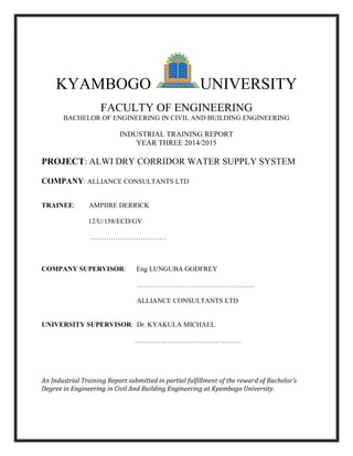
  • 1. KYAMBOGO UNIVERSITY FACULTY OF ENGINEERING BACHELOR OF ENGINEERING IN CIVIL AND BUILDING ENGINEERING INDUSTRIAL TRAINING REPORT YEAR THREE 2014/2015 PROJECT: ALWI DRY CORRIDOR WATER SUPPLY SYSTEM COMPANY: ALLIANCE CONSULTANTS LTD TRAINEE: AMPIIRE DERRICK 12/U/158/ECD/GV …………………………… COMPANY SUPERVISOR: Eng LUNGUBA GODFREY …………………………………………… ALLIANCE CONSULTANTS LTD UNIVERSITY SUPERVISOR: Dr. KYAKULA MICHAEL ………………………………………. An Industrial Training Report submitted in partial fulfillment of the reward of Bachelor’s Degree in Engineering in Civil And Building Engineering at Kyambogo University.
  • 3. ii iiAMPIIRE DERRICK 12/U/158/ECD/GV DECLARATION I, AMPIIRE DERRICK declare that the content contained in this industrial training report is entirely my original work and has never been submitted by someone else for the award of Bachelors of Engineering in Civil and Building engineering of Kyambogo University. It contains my findings during my industrial training. Signature……………………… Date ………………………… AMPIIRE DERRICK 12/U/158/ECD/GV Department of Civil and Building Engineering Faculty of Engineering Kyambogo University +256 794 62 07 66 / +256 703 57 99 88 ampderrick@hotmail.com
  • 4. iii iiiAMPIIRE DERRICK 12/U/158/ECD/GV PREFACE This report is an outcome of Industrial Training carried out in Nebbi district, Uganda with Alliance Consultants Ltd. The report has been compilation of the practical work done over the period in relation to the theoretical knowledge acquired in class about water supply and water treatment systems. The objectives of the industrial training include the following;  To enable the trainees get experience and be able to face the challenges of their field.  To equip students with the required knowledge of spear heading the construction process.  Providing an understanding of the basis of valuation of properties and material costs during construction.  Equipping students with knowledge and skills relating to property management, valuation and other relevant fields.  To provide trainees with knowledge and skills to identify building defects and design remedial measures and maintenance policies of buildings
  • 5. iv ivAMPIIRE DERRICK 12/U/158/ECD/GV ACKNOWLEDGEMENT First of all, I thank the Almighty God who gave me full life so I was able to work all the industrial training period without any serious illnesses. I also appreciate my family especially my mom for the time and support she has given to bring me up to this academic level I so much thank the lecturers, the university supervisor for the continued support towards my academic life to be a success. I also thank my mentor Arch Ssebunya Bashir for his continual guidance and instruction throughout my academic life. And finally I thank the Alliance Consultants Ltd team; the Managing Director Eng Joseph Kabanga, Eng Kaddu Sebuyira Amos, Eng Lunguba Godfrey, Eng Kabali Ssenteza William, Mr. Ssemujju Ivan who was in charge of my welfare, to mention but a few. They were willing to train me and the attention they gave me was amazing. This encouraged me to set my focus on this training and I surely learnt a lot as shown in this report. Thank you so much.
  • 6. v vAMPIIRE DERRICK 12/U/158/ECD/GV ABSTRACT I carried out my Industrial Training with Alliance Consultants Ltd in Nebbi district This report gives the details of the activities I was involved in due 15th June 2015 to 03rd August 2015 with Alliance Consultants Ltd who were the Project’s Consultants. The following are some of the activities that were accomplished during my training: plumbing works like laying and joinery off different pipes, steel tank assembly, concrete works like casting of rapid sand filter and clear water tank, tanking, carpentry works specifically formwork assembly, surveying, ground water technologies and visits to other sites.. I was wholly involved in the above works. However since the project was already underway, about 60% of the project work had been done and by the time I left it was about 80%. So, some of the preliminary works and other major field works were not observed such as site clearance and surveying works for setting out, tapping water from the intake etc. More is being detailed in this report as u read below
  • 7. vi viAMPIIRE DERRICK 12/U/158/ECD/GV TABLE OF CONTENTS DECLARATION ............................................................................................................................................... ii PREFACE....................................................................................................................................................... iii ACKNOWLEDGEMENT.................................................................................................................................. iv ABSTRACT...................................................................................................................................................... v TABLE OF CONTENTS.................................................................................................................................... vi LIST OF ACRONYMS AND ABBREVIATIONS ................................................................................................... x CHAPTER ONE ...............................................................................................................................................1 ORGANISATION STRUCTURE OF ALLIANCE CONSULTANTS LTD...................................................................1 1.1 Description and Background...............................................................................................................1 1.2 The Organization Structure.................................................................................................................2 CHAPTER TWO: BACKGROUND AND PROJECT INFORMATION.....................................................................3 2.1 Introduction ........................................................................................................................................3 2.1.1 General.........................................................................................................................................3 2.1.2 Background ..................................................................................................................................3 2.2 Major Components of the Works .......................................................................................................4 2.3 Districts and Community Liaison.........................................................................................................6 2.4 Supervision Work................................................................................................................................6 2.5 Site Handover and Commencement Date ..........................................................................................6 CHAPTER THREE: CONTRACT DATA ..............................................................................................................7 3.1 General................................................................................................................................................7 3.2 The client.............................................................................................................................................8 3.2.1 Background ..................................................................................................................................8 3.2.2 Vision............................................................................................................................................8 3.2.3 Mission.........................................................................................................................................8 3.3 Contractors .........................................................................................................................................8 3.3.1 Vision Statement..........................................................................................................................9 3.3.2 Mission Statement.......................................................................................................................9 3.3.3 Quality Policy Statement..............................................................................................................9 3.4 Site layout and organization ...............................................................................................................9
  • 8. vii viiAMPIIRE DERRICK 12/U/158/ECD/GV 3.4.1 Site general rules and time schedule...........................................................................................9 3.4.2 Health and Safety.......................................................................................................................10 3.4.3 Machinery and Equipment.........................................................................................................10 3.4.4 Materials’ supply and storage....................................................................................................12 3.4.5 Quality Control...........................................................................................................................12 3.5 Work progress, evaluation and communication...............................................................................13 3.5.1 How to Demand for water connection ......................................................................................13 CHAPTER FOUR: WATER INTAKE AND WATER STORAGE ...........................................................................14 4.1 WATER INTAKE WORKS.....................................................................................................................14 4.1.1 Gabion boxes and mattresses....................................................................................................14 4.1.2 Fencing at the water Intake .......................................................................................................15 4.1.3 Concrete pedestals ....................................................................................................................17 4.1.4 The intake chamber: ..................................................................................................................18 4.2 WATER STORAGE ..............................................................................................................................19 4.2.1 Assembly of a water reservoir tank ...........................................................................................19 CHAPTER FIVE: PIPE WORK.........................................................................................................................21 5.1 Introduction ......................................................................................................................................21 5.2 Surveying for pipes............................................................................................................................21 5.2.1 Levelling process of a Dumpy Level ...........................................................................................21 5.2.2 Using and Levelling of the total station .....................................................................................23 Types of pipes .........................................................................................................................................26 5.3 High Density Polyethylene (HDPE) pipes ..........................................................................................26 5.3.1 Advantages of HDPE pipes.........................................................................................................26 5.3.2 Joining of HDPE pipes.................................................................................................................27 5.4 STEEL PIPES .......................................................................................................................................29 5.4.1 Joinery by welding......................................................................................................................30 5.4.2 Joinery by Flange connections...................................................................................................31 5.5 DUCTILE IRON PIPES..........................................................................................................................32 5.6 uPVC (Un-plasticised Polyvinyl Chloride)..........................................................................................33 5.6.1 Joinery of uPVC pipes.................................................................................................................33 5.6.2 Joinery of uPVC to steel pipes....................................................................................................35 5.7 Thrust blocks.....................................................................................................................................36
  • 9. viii viiiAMPIIRE DERRICK 12/U/158/ECD/GV 5.7.1 Casting of Thrust Blocks.............................................................................................................36 CHAPTER SIX: FORMWORK AND CONCRETE...............................................................................................37 6.1 FORMWORK ASSEMBLY....................................................................................................................37 6.1.1 Formwork assembly of the clear water tank. ............................................................................38 6.1.2 Formwork assembly for rapid sand filter...................................................................................38 6.1.3 Formwork for dwarf walls..........................................................................................................38 6.2 CONCRETE PREPARATION AND CASTING..........................................................................................40 6.2.1 Concrete production..................................................................................................................40 6.2.2 Making spacer blocks.................................................................................................................41 6.2.3 Concrete production by Hand Mixing........................................................................................41 6.2.4 OPERATING THE MIXER..............................................................................................................42 6.2.5 Casting process ..........................................................................................................................43 6.3 Tests on concrete..............................................................................................................................44 6.3.1 SLUMP CONE TEST .....................................................................................................................44 6.3.2 COMPRESSIVE STRENGTH TEST OF CONCRETE..........................................................................46 6.3.3 Using the Compressive Strength test Machine..........................................................................47 CHAPTER SEVEN: WATER TREATMENT PLANT............................................................................................49 7.1 Raw water screening.........................................................................................................................49 7.2 Coagulation.......................................................................................................................................49 7.3 Flocculation.......................................................................................................................................50 7.4 Sedimentation/Clarification..............................................................................................................51 7.5 Filtration............................................................................................................................................52 7.6 Final Chlorination..............................................................................................................................52 CHAPTER EIGHT: OTHER WORKS ................................................................................................................53 GROUND WATER TECHNOLOGIES (BOREHOLES)........................................................................................53 8.1 Implementation ................................................................................................................................53 8.2 Ground water investigation..............................................................................................................54 8.2.1 Resistivity method......................................................................................................................54 8.3 Drilling...............................................................................................................................................55 8.3.1 Rotary drilling.............................................................................................................................55 8.4 Development of the well. .................................................................................................................55 8.5 Determining the yield: ......................................................................................................................55
  • 10. ix ixAMPIIRE DERRICK 12/U/158/ECD/GV 8.6 Test pumping. ...................................................................................................................................56 8.7 Installation. .......................................................................................................................................57 8.7.1 Procedure of installation............................................................................................................57 8.8 Types of borehole wells ....................................................................................................................58 8.9 Post construction/O&M phase. ........................................................................................................58 CHAPTER NINE: PROBLEMS, SOLUTIONS AND CONCLUSION.....................................................................59 9.1 PROBLEMS:........................................................................................................................................59 9.2 SOLUTIONS........................................................................................................................................60 9.3 CONCLUSION.....................................................................................................................................60 APPENDIX 1 DRAWINGS..............................................................................................................................61 APPENDIX 2: PHOTOS .................................................................................................................................64
  • 11. x xAMPIIRE DERRICK 12/U/158/ECD/GV LIST OF ACRONYMS AND ABBREVIATIONS BPT Break Pressure Tank DN Nominal Diameter DWD Directorate of Water Development ESIA Environmental and Social Impact Assessment GI Galvanised Iron GoU Government of Uganda hr Hour HC House connection HDPE High Density Polyethylene IPC Interim Payment Certificate km Kilometre kWh Kilowatt hour l Litre LC Local council lcd Litres per capita per day m Metre m3 Cubic metre m/s Metres per second MWE Ministry of Water and Environment No. Number OD Outside diameter PAP Project Affected Persons PSP Public stand post RGC Rural Growth Centre uPVC un Plasticised Polyvinyl Chloride UGx/UShs. Uganda Shilling YT Yard Tap
  • 12. 1 1AMPIIRE DERRICK 12/U/158/ECD/GV CHAPTER ONE ORGANISATION STRUCTURE OF ALLIANCE CONSULTANTS LTD 1.1 Description and Background Alliance Consultants Ltd is a limited liability engineering consultancy firm but predominantly in Hydraulic Engineering. It started 30th June 2003 as per registration date. It’s composed of a team of well trained personnel able to take the standards of Uganda’s and in general Africa’s engineering to extreme aptness. Below are the details of its location and contact information; Physical Address: - Plot No: 398 - Floor no.: 2nd floor, The Ark House - Street: Gayaza Road, Mulago - Town: Kalerwe - District: Kampala - Country: Uganda Telephone: +256 414 530160 P.O Box: 33975, Kampala Email: allianceconsultantsltd@gmail.com On the next page is the organization structure of this company.
  • 13. 2 2AMPIIRE DERRICK 12/U/158/ECD/GV 1.2 The Organization Structure Board of Directors Technical Director F.Ddumba Head finance, Logistics & Administration Amos Sebuyira Secretary Annette M. Ndawula Office Attendant Sarah Nakabiri Managing Director Joseph K. Kabanga Engineers / Technicians P. Ssekadde H,Mayombwe K,Gyavira A Out Source Contract Staff Administrative Staffs
  • 14. 3 3AMPIIRE DERRICK 12/U/158/ECD/GV CHAPTER TWO: BACKGROUND AND PROJECT INFORMATION 2.1 Introduction 2.1.1 General The Government of Uganda is committed to a policy for the increased provision of safe water supply and adequate sanitation to the whole population. The Rural Water and Sanitation Investment Plan and Strategy aims at provision of safe and adequate water and sanitation facilities for all by the year 2015. Gravity flow scheme (GFS) development is among the technologies that have been used for improved water supply in rural areas. The Ministry of Water and Environment (MWE) through the Directorate of Water Development (DWD) is supporting Districts in planning and development of large gravity flow schemes to serve a larger number of beneficiaries across Local Government boundaries. As part of this strategy, the Nyarwodho Gravity Flow Scheme is being developed to supply population centres in the District of Nebbi. 2.1.2 Background Nyarwodho Gravity Flow Scheme Project was conceived by Nebbi District in 2011 as a contribution to the goal of increasing safe drinking water coverage in the water stressed areas of Jonam County and Padyere County. In 2012 MWE assumed responsibility for the development of the scheme commencing with a Feasibility / Design Review, preparation of Tender Documents and subsequent construction. The Project covers 9 sub-counties in Nebbi District i.e Alwi, Pakwach & Panyango of Jonam County and Kucwiny, Nebbi, Ndhew, Atego, Nyaravur and Parombo of Padyere County. The population to be served is presented in the table below. Owing to the size of the scheme, the Project will be implemented in phases.
  • 15. 4 4AMPIIRE DERRICK 12/U/158/ECD/GV Nyarwodho GFS Projected Population to be served County Sub County Projected Populations in Supply Area 2013 2033 Jonam Alwi 7,645 13,540 Pakwach 5,123 9,080 Panyango 6,861 12,150 County Total 19,628 34,770 Padyere Kucwiny 8,932 15,822 Nebbi, Ndeu & Atego 4,504 7,970 Nyaravur 6,400 8,520 Parombo 10,445 18,500 County Total 28,689 50,812 GFS Project Total 48,340 85,750 2.2 Major Components of the Works The major components of the works are; - Intake Works: Water abstraction from the River Nyarwodho, Erussi sub - county, Nebbi District. - Raw Water Main: 4.8km of OD250 uPVC pipeline with DN250 steel for sections which run above ground. - Water Treatment Plant: A 4,000m3/d water treatment plant located in Kei village, Erussi sub - county, Nebbi District. The system components are as follows:-  Coagulation and flocculation in baffled horizontal flow chamber  Sedimentation tank in rectangular flow chambers  Three rapid gravity filters  Treated water tank  Chemical house, office & laboratory with equipment  90m3 Backwash tank  Backwash pump house with solar powered system
  • 16. 5 5AMPIIRE DERRICK 12/U/158/ECD/GV - Transmission Mains: 32.3km of OD280 – OD110 uPVC treated water mains with 2No. 10m3 break pressure tanks. - Storage Tanks: Pressed steel sectional ground level tanks of 31, 158 and 222m3 in Oweko, Nyaravur and Goti-Madi respectively. - Distribution Mains: 40.2km of primary distribution pipelines in OD40 - OD90 HDPE and 15.2 Km of OD110 – OD 250 uPVC and 55.7km of secondary distribution. Transmission, Storage and Distribution Systems Transmission length (m) Tanks supplied (m3) Independent Distribution system (m) Oweko 31 1,650 1,451 Nyaruvur 158 27,570 6,720 Goti-Madi 222 28,930 Totals 58,150 - Customer Connections: Water points will be installed on a demand-driven approach where services will be installed at household level to serve individuals or groups of individuals that have duly applied, confirmed as meeting the sanitation guidelines, and paid a nominal fee. This will be preceded by consumer awareness and sanitation campaign to be conducted by a DWD Sociologists team. - Office Block: 80m2 office blocks in Nyaravur and Alwi were equipped and furnished under the Contract.
  • 17. 6 6AMPIIRE DERRICK 12/U/158/ECD/GV 2.3 Districts and Community Liaison Crop compensation for PAP in the Sub – Counties of Ndhew, Atego and Nyaravur was still under scrutiny by the Directorate of Water Development. Crop compensation had been made to the Sub-Counties of Erussi, Nebbi Town Council and Nebbi Sub – County. The Mobilization team had been very vigilant in the field whenever they are called upon to attend to community issues. Reservoir sites of Oweko, Nyaravur and Goti-Madi were acquired (Agreements were signed between the land owners and payments effected) The Community Mobilization team at the District and Sub County continued to sensitize and mobilize the Communities within the project area but most especially those along the pipeline. The mobilisers move ahead of the Contractors route survey team i.e. mobilisation precedes the excavation and eventual pipe laying. The land for the Water Offices at Nyaravur and Alwi, was offered free of charge by the sub counties. 2.4 Supervision Work Due to the afore mentioned events, Overall project (Singila & Wadelai RGCs and Nyarwodho GFS) implementation period increased from the original twelve (12) months to thirty three (33) months. Original Consultancy Contract was to expire on 28th July 2014. The Consultant requested for the Contract to be extended to 31st January 2015 within the original costs and thereafter the Client was advised to initiate the process of procuring Construction Supervision Services to cover the period: February 2015 to end of Construction: February 2016 and the twelve (12) months to cover the defects liability period ending February 2017 in case it was not possible to extend the contract beyond 31st January 2015. 2.5 Site Handover and Commencement Date The Commencement Date for construction Works was 3rd February 2014. The construction site was handed over to the Contractor on 11th February 2014 The Ground Breaking ceremony was held on 20th May 2014 and it was presided over by the Minister for Water & Environment, Hon. Prof. Ephraim Kamuntu and it was attended by various dignitaries from the MWE, DWD, Nebbi District Local Government, and Lower Local Governments to be traversed by benefit from the project and community member.
  • 18. 7 7AMPIIRE DERRICK 12/U/158/ECD/GV CHAPTER THREE: CONTRACT DATA 3.1 General Project Title: Alwi Dry Corridor Water Supply Project (Construction of Nyarwodho Gravity Flow Scheme Water Supply and Sanitation System Lot 1- Oweko, Naravur & Alwi in Nebbi District) Client: Ministry of Water and Environment. Contract No: MWE/WRKS/12-13/01707 Project Funding: Government of Uganda (100%) Supervising Engineer: ALLIANCE CONSULTANTS LTD in association with Infra-Consult Ltd. Contractor: Vambeco Enterprises Ltd Date of Site Hand-Over to Contractor: 11th February 2014 Commencement Date: 3rd February 2014 Contract Period: 24 Calendar months Completion Date: 3rd February 2016 Contract Sum: UGX 25,717,827,680 (VAT exempt)
  • 19. 8 8AMPIIRE DERRICK 12/U/158/ECD/GV 3.2 The client The client was Ministry Of Water and Environment (MWE) 3.2.1 Background Ministry of Water and Environment (MWE) is the ministry that has the responsibility for Water & Environment management in terms of Policy Formulation, Water resources Management, Resource Mobilization/Allocation and Regulation and Sanitation. Sanitation is a shared responsibility between MWE, Ministry of Health, Ministry of Education and Sports and the Respective Local Governments. MWE is fully responsible for Sewerage 3.2.2 Vision “Sound management and sustainable utilization of water and environment resources for the betterment of the population of Uganda” 3.2.3 Mission “To promote and ensure the rational and sustainable utilization, development and effective management of water and environment resources for socio-economic development of the country” 3.3 Contractors The contractors were Vambeco Enterprises Ltd which is mainly a construction management company. It has quite a wonderful construction experience and outstanding project history. They provided all the equipment and laborers required for the project. They pride ourselves on being one of the few independently owned and managed firms that performs all facets of construction and water projects, from installing the meter for your home to distribution systems that feed villages. Their expertise includes all types of construction. With over 10 years of experience in the industry, they have a well-diversified and well trained workforce that has the necessary knowledge and expertise to exceed industry standards for construction while striving to provide customers with the best possible service they can experience. The Vambeco philosophy is “Quality is Number One.” Their eye is on the future and they are a growth oriented company looking for the right individuals to help them continue to be successful.
  • 20. 9 9AMPIIRE DERRICK 12/U/158/ECD/GV Their Affiliates 3.3.1 Vision Statement To be the leading construction company especially in water-works in East Africa with an expanded presence throughout Africa. 3.3.2 Mission Statement To provide the highest quality construction services through constant upgrading of our staff skills, creating equal opportunity, protecting the environment and discharging our corporate social responsibility. 3.3.3 Quality Policy Statement Vambeco Enterprises Limited is committed to employing quality employees, and shall strive to satisfy our customer’s needs by executing the works to consistently high quality standards at competitive prices and within the time-frame agreed to. 3.4 Site layout and organization This section includes the contractor information and site work 3.4.1 Site general rules and time schedule Most of the workers were residents in Nebbi and the workers weren’t had a home set up for them. They would leave their homes early enough so that by 7:00am they are at the contractor’s office where they load materials on to the available trucks and by 8:00am they set off. Usually there could be 3 sites running at the same time and in extreme cases 5-6 sites running co-currently on the same day. So sometimes there would be delays when cars were mechanically down Breakfast would be served immediately and materials to be used would be offloaded so that by 9:00am, work kicks off. Lunch was served from 1:00pm to 2:00pm Standard time for work to close was 6:00pm.
  • 21. 10 10AMPIIRE DERRICK 12/U/158/ECD/GV 3.4.2 Health and Safety Health and safety gear was available and supplied to the workers upon delivery of every consignment. Standard equipment for each worker includes;  Helmet  Overall  Gum boots. But since we came in the latter stages of the project, some of this safety gear wasn’t given out as it was earlier. The contractors required the workers to come with their personal safety items before they could be employed. First Aid was given especially for minor cuts, nausea and headaches by medication being provided by two nurses who moved with their first aid kits on site. In case of serious injuries which couldn’t be treated on site, the casualty would be transported in the company vehicle to hospital. The water available at the sites was usually river water, borehole water was too saline and the packed mineral water in shops was too expensive for the workers to buy. So clean and fresh water was provided for drinking and cooking. It would be loaded on the vehicles before leaving the contractor’s office. Trusted cooks who were under the contractors did the cooking. One or two cooks, depending on the number of workers, were taken to each active site. I happened to share with the workers several meals and it was indeed nice food and at least I didn’t hear of any ailments that arose due to eating the food. Bravo! 3.4.3 Machinery and Equipment The heavier machinery include;  Concrete Mixers.  Pedestrian Roller  Pick-Up and Tippers  Wheel loaders with back actor  Block making machine  Generators  Welding equipment I’ll talk about a few of the above equipment
  • 22. 11 11AMPIIRE DERRICK 12/U/158/ECD/GV Generator Generators were generally used as a power source for welding process. For the one shown below, it was a single phase diesel generator of rated power 2.8kVA, rated frequency 50/60Hz and rated current 12.2A weighing 191kg. A welding torch/angle grinder was connected to the cathode and another cable with an open end was connected to the anode then to a metal piece so as to complete a circuit. It would then be switched on by pressing the power button. Angle Grinder It was used to mainly cut pipes to required sizes especially steel pipes, for pipework at treatment plant and transmission mains. Care should be taken while using it as it was considered the most dangerous equipment on site. The angle grinders were manufactured by Makita with voltage 220V and rated frequency 50/60Hz.
  • 23. 12 12AMPIIRE DERRICK 12/U/158/ECD/GV 3.4.4 Materials’ supply and storage Materials were delivered on site by tippers. Cement was stored at the contractor’s office. Types of cement used were Power Plus cement, and multipurpose cement of the classes 42.5N and 22.5N respectively. And deliveries made to site depending on the work to be done Sand was from Akaba in Nyaravur sub county Nebbi The 20mm aggregate was also obtained from a quarry plant in Nebbi. All materials were safely kept in a store with a trusted store keeper to monitor the use or else the site had to be hoarded for materials that are stored outdoor like aggregate, sand, machines etc. Pipes were supplied by GENTEX and Simba Multiple Industries Ltd both located in Kampala, Uganda Delivery of HDPE pipes on a truck Stacked uPVC pipes under a shade 3.4.5 Quality Control Tests especially on concrete were done in Arua district at the Uganda National Roads’ Authority (UNRA) concrete laboratory. I was able to take part in some of the tests as explained in chapter six section 6.3 Otherwise most of the other materials had to be accepted before they could be transported to site.
  • 24. 13 13AMPIIRE DERRICK 12/U/158/ECD/GV 3.5 Work progress, evaluation and communication The work done was evaluated on a weekly basis. Meetings were usually between the client representatives, the consultants, the contractors and local leaders especially on Thursdays or Fridays. An agenda of a typical site meeting is as follows  Opening prayer  Introduction and expectation  Briefing  Questions and Answers( Q & A)  Developing action plan  Conclusion For example; a meeting was held on 24th July 2015 at Leosim Hotel, Nebbi district between by the client, consultants, Nebbi district local government and sub county representatives of Kucwiny and Ndhew. The project was explained in detail to them and these are some issues which were brought up 3.5.1 How to Demand for water connection  Express interest by visiting the sub county water office  Fill application form  Fulfill all hygiene requirements and other conditions  Pay for connection Payment is according to;  Water Act Cap 152(1997)  National Water Policy (1999)  Tariff Policy (2008) An action plan was developed as follows  Formation and submission of the names of the planning committee members  Community members picking and submitting forms to sub county  Display and assessment of applicants’ households  Displaying the final list of payments  Connections by consultants and contractor
  • 25. 14 14AMPIIRE DERRICK 12/U/158/ECD/GV CHAPTER FOUR: WATER INTAKE AND WATER STORAGE This chapter is mainly about the water source and works involved at the water source and also describes the assembly of the water reservoir tanks located in the various selected areas. 4.1 WATER INTAKE WORKS Water abstraction from the River Nyarwodho, Erussi sub - county, Nebbi District.  Identification of Intake point  Gabion boxes and mattresses  Pipework  Concrete pedestals  Anchor blocks  Intake chamber  Chain link fence and Gate 4.1.1 Gabion boxes and mattresses River Nyarwodho originates from the Democratic Republic of Congo highlands and the point selected where the intake was located in the upstream of the river. The base of the river at the specific point was also irregular because of the rocky formation of the ground causing the turbulent flow in the movement of water and this couldn’t be dealt with by crushing because of the high costs. Therefore the speed of the water had to be reduced to make it possible to draw water from the river by creating a small reservoir to keep the flow of water at a constant speed and to acquire a constant amount during the dry and wet seasons of the year. The laying of the gabion boxes and mattresses was done in the dry season of the year when the water level of the river is low  The base of the river at the intake point was made regular by laying gabion mattresses 2m x 1m x 0.3m, in galvanised steel wire fabric 50 x 50mm filled with rock of size 50 – 150mm. This was also to stop water from penetrating through to the other side of the gabion.  Gauge 1000 polythene sheet was placed between two layers of the gabion mattresses to stop water from penetrating through.  Gabion boxes 2m x 1m x 0.5m, in galvanised steel fabric 50m x 50mm filled with rock 150 – 300mm were lay to create the vertical barrier.  Gauge 1000 polythene sheet was placed between two layers of the gabion boxes to stop water from penetrating through. The weight of the gabion mattresses and boxes is strong enough to resist all the water pressure imposed by the water approaching.
  • 26. 15 15AMPIIRE DERRICK 12/U/158/ECD/GV Placing of Gabions at Intake Site 4.1.2 Fencing at the water Intake Chain link fences were used at all the constructed sites at the water intake, water treatment plant, water reservoir tank sites and site offices Procedure of fencing  We first identified the area to be covered and then cleared away all obstructions to ensure a reasonable level before pegging out the line of the chain link fence with string.  We marked the position of the end straining concrete poles and dug holes for their foundations. Holes were about 750mm deep and 500mm square  We then planted the end straining post and hand mixed concrete poured in the hole so the bottom end of the post is embedded  We then fixed a line taut between the straining posts and set the intermediate standards along this line at 2.5m intervals.  The concrete poles were plumbed with timber props until and the concrete sets and hardens.  The intermediate standards were then also placed using the same procedure as the end straining posts.  Then we unrolled the chain link fencing along the line of the fence pulling the mesh as tight as possible as an assistant moves along. Then hold the fence to the line wire using temporary tying wire or strings at intervals.  We then fastened the mesh to each straining post in turn and then continued to complete the fence by connecting it by the tying wires.  Barbed wire was then attached at the top of the poles to limit access of intruders jumping over the fence
  • 27. 16 16AMPIIRE DERRICK 12/U/158/ECD/GV NOTE: At Oweko water reservoir tank, the ground was rocky so excavating up to 750mm was not possible. The solution was a 500mm square pad un-reinforced concrete base was cast around the pole and 250-300mm deep depending on the how deep the excavated hole depth. This was by instruction of the foreman Concrete ratio used was 1:2:4 (cement:sand:coarse aggregate) and was prepared by hand mixing. Hand mixing is described in detail Chapter six (section 6.2.3). Cutting tying wire with a pincher. Casting concrete for a plumbed concrete pole
  • 28. 17 17AMPIIRE DERRICK 12/U/158/ECD/GV 4.1.3 Concrete pedestals  The ground was prepared for concrete and the pipes were supported by wooden supports before the installation of the concrete pedestals.  Excavation was done at a stated depth according to directions from the consulting engineer at positions with weak base were concrete pedestals were to be placed.  Formwork was then made using wood with fair finish in the interior for the bases of the 1 x 1 x 0.5m and 0.8 x 0.8 x 0.4m and were supported and plumbed.  Formwork for the rest of the pedestal was then put up 0.5 x 0.3m with different heights following the gradient the pipe is to follow to the intake chamber.  Steel reinforcement was made and fixed for the different pedestals High yield steel square twisted bars Y12 at 150 c/c and Y16 at 150 c/c  The bases were made wet by pouring water to favour the joinery of concrete to the bases of the existing ground.  Cement grout was then poured that is a mixer of water and cement to the base of the existing ground.  Concrete blinding class C15 was cast 50mm thickness using multipurpose cement of strength 32.5N mix ratio 1:2:3  Concrete for the base and the pedestal wall was then cast too of class C30 using powerplus max cement of strength 42.5N mix ratio 1:2:3 Concrete pedestals supporting ductile iron pipe. Striking formwork off a concrete pedestal.
  • 29. 18 18AMPIIRE DERRICK 12/U/158/ECD/GV 4.1.4 The intake chamber: This structure is designed in a way that helps to remove silt that escapes through the transmission line before reaching the treatment plant. It also blocks entry of bigger undesirable particles from entering the pipes e.g. frogs, fish etc. This process is known as screening. The Screen at the intake.
  • 30. 19 19AMPIIRE DERRICK 12/U/158/ECD/GV 4.2 WATER STORAGE Water was stored in three water reservoir tanks they were pressed steel sectional ground level tanks of 31, 158 and 222m3 in Oweko, Nyaravur and Goti-Madi respectively. 4.2.1 Assembly of a water reservoir tank I took part in assembly of the tank at Oweko. Below are the steps we took  The tank is assembled on reinforced concrete dwarf walls which are cast 1m above finished ground level. The process of constructing these walls is explained in Chapter Six.  1.22m square tank bottom plates were bolted to each other with rubber plugs placed at lining between plates. Rubber plugs provide blockage to leaking along the plate lining.  Plates should be clearly and accurately labelled and care should be taken as exact plates should be laid as indicated on the plan. A placement of a plate at a wrong position may cost you disassembling the whole steel tank. It also ensures the inlet flange, washout, outlet flange and overflow are placed rightly.  The side plates are then also bolted with rubber plug in between and fixed to the bottom assembly. They should be fixed firmly enough so that they cannot fall off.  The bolts should not be fixed very tightly as yet since there’s need to adjust plates when assembling the tank.  Angle linings are also fixed to the side plates on which a ladder is tightened with ropes as scaffold to assemble the top plates and roof of the tank.  After assembling all the side plates, enter the tank and fix the joint and corner covers at the bottom assembly and also the tank stays and tank cleats on the side plate assembly. The tank stays are to ensure the tank is square while the cleats and covers to limit leakage at points of placement.  The roof cover gables, stiffeners, apex and rafters are fixed and the roof cover plates bolted onto them.  The internal and external ladders are fixed and then all the bolts are finally tightened very firmly to finish the tank.
  • 31. 20 20AMPIIRE DERRICK 12/U/158/ECD/GV Tightening bolts. Fixing tank cleats. Placement of the tank roof.
  • 32. 21 21AMPIIRE DERRICK 12/U/158/ECD/GV CHAPTER FIVE: PIPE WORK 5.1 Introduction A pipe is a closed conduit generally of circular section used to carry water or any other fluid, but in this case it was water. When a pipe is running full, the flow is under pressure but when it isn’t running like in sewers or culverts, the flow is not under pressure but rather atmospheric pressure exists in the pipe. Flow in pipes is therefore due to a pressure gradient. It’s due to this gradient that pipes of different pressure ratings (PN 6, PN 10, and PN 16) were used across the profiles- the transmission and distribution mains. PN stands for Pressure Nominal the pipe can support with water at 20oC and only 3 pressure grades of the pipes were used in this project  PN 6- maximum pressure 6 bar where  PN 10 – maximum pressure 10 bar 1 bar = 105 Pascals  PN 16 – maximum pressure 16 bar Pipes were supplied by GENTEX and Simba Multiple Industries Ltd both located in Kampala, Uganda 5.2 Surveying for pipes Before pipes were laid, surveying would be done to provide profile details for the water mains. Pegs would then be set up along the water mains to guide the plumbers while laying pipes. The main instruments used were a dumpy level and a total station. A dumpy level was used over small areas mainly to get the elevation/height differences over an area while the total station was the key instrument used for setting out. Below are steps taken in the levelling process and use of both instruments. 5.2.1 Levelling process of a Dumpy Level This is a simple procedure on how to set up the dumpy level; - The tripod has its legs firmly fixed into the ground trying to ensure that the tripod table is relatively flat and the instrument is then mounted on to it. - After mounting the instrument onto the tripod, using the three foot screws, u may now level the instrument by rotating the telescope to be by parallel a given set of two foot screws and after which these screws are turned gently and simultaneously in opposite directions until the bubble is brought to the center of its runs. If this is attained, the telescope is then made perpendicular to the third foot screw and this screw is again rotated until the bubble returns to the center of its run again.
  • 33. 22 22AMPIIRE DERRICK 12/U/158/ECD/GV - If this is attained, the telescope is then rotated to face any other direction and if the bubble settles back to the center of its run, the leveling procedure is done. If it does not return to the center of its run, the procedure is then repeated. - The final step is to focus the onto the target using the eyepiece lens to view the target clearly and then using the objective lens to attain fine cross hairs and those that are not blurred. This is done to eliminate parallax. After following all the above steps, the instrument is now ready to use and the only thing left to do is to take the readings by focusing on the staff.
  • 34. 23 23AMPIIRE DERRICK 12/U/158/ECD/GV 5.2.2 Using and Levelling of the total station A total station consists of a theodolite with a built-in distance meter (distancer), and so it can measure angles and distances at the same time. In order to describe the position of a point, two coordinates are required. Preparation for use Levelling - Place the tripod approximately over the ground point. - Inspect the tripod from various sides and correct its position so that the tripod plate is roughly horizontal and above the ground point. - Push the tripod legs firmly into the ground and use the central fixing screw to secure the instrument on the tripod. - Switch on the laser plummet and turn the footscrews so that the laser dot or the optical plummet is centred on the ground point; it was usually the centre of a nail of a temporary bench mark - Centre the bull’s-eye bubble by adjusting the lengths of the tripod legs.
  • 35. 24 24AMPIIRE DERRICK 12/U/158/ECD/GV - After accurately levelling up the instrument, release the central fixing screw so that you can displace it on the tripod plate until the laser dot is centred precisely over the ground point. - Tighten the central fixing screw again. Setting up: Orientation Method - Set Job: Select “Set Job” and enter in respectively - SetStation: The screen then goes to SURVEYING and select “SetStation” and enter in respectively (see below). You can also enter the height of the Total Station above the survey point by measuring this with a tape measure and entering it. This will make all height measurements relative to the survey point, rather than the Total Station. Height was either 1.300m or 2.150m depending on how the prism was used. Set Orientation: Since some temporary bench marks (TBMs) had already been set, this process was to be a confirmation of the accuracy of the levelling of the instruments. Focus at the prism at the second point should give a reading which is within the acceptable error of the previous reading. Swing the Total Station so that the cross-wires are aligned with the mark on the cross-wires at the second point. If the error is acceptable. Continue.
  • 36. 25 25AMPIIRE DERRICK 12/U/158/ECD/GV Select Start: after the above process, select “start” and begin taking your reading while neatly noting them in a book. After taking the readings, switch it off, carefully unscrew it from the tripod and pack it in its box including the prism. An example of information developed from the surveying process is recorded as shown below; PROFILES - PRIMARY DISTRIBUTION MAINS Nyaravur to Pakwach Chainage (m) Ground level Pipe Details Fittings 0+000 1040.1 2033mx OD110 PN10 Tee at Nebbi - Packwach Rd Junction 1+157 1019.2 2+033 1016.1 Tee to Parombo before BPT to Pakwach 2+033 1016.1 1600mx OD63 PN6 3+633 955.88 3+633 955.88 1607mx OD50 PN10 5+240 928.21 5+240 928.21 3040mx OD50 PN16 end of survey; WO + end cap 8+280 884.3 8+280 884.3 1391mx OD50 PN16 9+671 883.99 9+671 883.99 870mx OD40 PN16 end of design pipeline; alternative WO + end cap 10+541 877.21
  • 37. 26 26AMPIIRE DERRICK 12/U/158/ECD/GV Types of pipes 5.3 High Density Polyethylene (HDPE) pipes They are very popular for water pipes and were used on the distribution mains. HDPE pipes were black in colour and sunlight is not a concern if black pipe is used. Carbon black, utilized in most all HDPE pipe is the most effective ultraviolet stabilizer and therefore, black is the recommended pipe color for exposed long term service or storage. 5.3.1 Advantages of HDPE pipes  Leak free: HDPE pipe is normally joined by heat fusion. Butt, socket, sidewall fusion and electrofusion but we were using butt welding which creates a joint that is as strong as the pipe itself, and is virtually leak free.  Corrosion, abrasion and chemical resistant: HDPE has excellent corrosion resistance and is virtually inert. It does not need expensive maintenance or cathodic protection. It offers better overall resistance to corrosive acids, bases and salts than most piping materials. In addition, polyethylene is unaffected by bacteria, fungi and the most “aggressive” naturally occurring soils.  Excellent Flow Characteristics: Because polyethylene is smoother than steel, cast iron, ductile iron, or concrete, a smaller PE pipe can carry an equivalent volumetric flow rate at the same pressure. It has less drag and a lower tendency for turbulence at high flow  Lightweight and flexible: HDPE pipe is produced in straight lengths or in coils. Made from materials about 1/8 the density of steel, it is lightweight and does not require the use of heavy lifting equipment for installation. It reduces the need for fittings and performs well in earthquake-prone areas. Since HDPE is not a brittle material, it can be installed with bends over uneven terrain easily in continuous lengths  Ductility and toughness: HDPE pipe and fittings are inherently tough, resilient and resistant to damage caused by external loads, vibrations, and from pressure surges such as water hammer. Even in cold weather polyethylene pipe is tolerant to handling and bending.
  • 38. 27 27AMPIIRE DERRICK 12/U/158/ECD/GV 5.3.2 Joining of HDPE pipes I was able to take part in one process of connection known as butt welding and it’s described below; Equipment; Butt welding machine (heating plate, pipevice/alignment jig, shaver), stool, diesel generator, metallic saw Welding procedure  Preparation: The HDPE pipes were first pulled out from the pits if they were already lengthened out. So they appear out above the ground level and make sure you have sufficient working space.  Assembling the pipe vice; here, a stool would be placed on a fairly flat ground. It’s the working platform where the butt welding equipment is assembled. The pipe vice would then be tightened by the bottom clamps so that it flashes with one side of the stool edges.  The alignment of the pipe: The pipes were aligned when they are clamped into the mirror welder in such a way that the surfaces are in the same plane (parallel) to each other. The HDPE pipes were positioned directly into the welding machine. Since sometimes pipes of different diameters were used, we would install the correct adapter insert for the size of pipe diameter to be used and tighten them to the machine. Then position the pipe in a way that approx. 50mm is protruding behind the last clamp. By doing this, you will have approx. 10 to 15mm to shave from, and the remaining 25 to 30 mm should be sufficient for welding. Once the pipes were placed in position, the top clamps were closed. It is important to tighten the top clamp nuts evenly in order to get a totally circular pipe, an even clamping pressure must be achieved. Then, make the first dry matching (press the two pipes to each other) and check the amount of shaving that will be required.  The shaving of the surfaces of the pipe ends: After the dry matching was completed, we opened up the pipes and introduced the shaver. Then pressed the two pipes together, and shove until a continuous strip of HDPE was peeling off on both sides of the shaver. Once constant peeling off was observed, release the pressure on the pipes and separate the pipes. Do not stop shaving until the pipes are apart. Remove the shaver, match the pipes again, and check the pipe for proper alignment. Sometimes, even when continuous peeling off is achieved on each side of the shaver, the pipes do not match properly. This is normally due to the clamps, which are pressing on to the pipe with different pressures. Re-tightening the nuts slightly on either side would be one solution. The assistants would then hold the pipes in this position and the shaver slowly removed.
  • 39. 28 28AMPIIRE DERRICK 12/U/158/ECD/GV  Heating of surfaces: after the shaving process, a heating plate was then introduced between the pipes and the pipes tightened on both sides of the plate. The generator as the power source would then be started and the pipes heated up to melt. Depending on the pipe wall thickness, the heating process was taking 10- 15minutes.but care would be taken so it doesn’t melt beyond what’s required.  Fusion of surfaces: with the assistants still holding the pipes, the generator would be stopped and the heating plate quickly removed and placed somewhere safe so it doesn’t burn up anyone. This is where you would temporarily shut your ‘heat feeling senses’ in the hands and quickly join the melted bit. It was usually done by two people. They stand opposite each other and place the melted bit with two fingers as you move along the pipe to form a straight raised line at this point. It’s permanent.  Cooling of weld joint: Cooling time is the time in which the pipe has to be left undisturbed. Under no circumstances would the clamps be opened or the pressure released until the cooling time has elapsed. You keep touching the pipe so you can know if the pipe has cooled down.  After cooling disassemble the equipment and place the pipe into the pit so that this single unit of pipes is buried. When HDPE pipe is buried, the temperature of the system becomes much more stable than an above ground pipeline and therefore will exhibit far less dimensional change. In most systems, buried HDPE pipe does not move after it is buried. All pipes expand and contract with change in temperature. The key is management of the resultant thermal strain. Also buried pipelines usually do not move due to soil friction. However, thermal effects must be considered for above grade applications.
  • 40. 29 29AMPIIRE DERRICK 12/U/158/ECD/GV Melting the pipes using a heating plate Shaving the pipe surfaces with a shaver 5.4 STEEL PIPES They were used above ground level and not like uPVC pipes which were buried underground after laying. Since they were heavy about 750kg (OD 280mm pipes), 8 energetic workers would carry one pipe to the desired place. In a day, they could probably transport 2 pipes on their shoulders to site. They were frequently used where pressures are high, large diameter pipe is required and above ground. Steel pipe has high strength and stiffness (modulus of elasticity). It is comparatively inexpensive, easy to install, and more easily transported than ductile iron pipe; however, steel pipe cannot withstand the external loads that DIP can. Because it is metallic, steel pipe is subject to corrosion and the corrosion is oftentimes more severe in steel pipe than DIP. Though cement-mortar lining and coating is often used to protect both the interior of the steel pipe Steel pipe can be joined together using different methods but we were only exposed to welding, use mechanical couplings or fittings and flange connections. Mechanical coupling will be described below in connection of uPVC pipes in section 5.6.2 but below is the welding process.
  • 41. 30 30AMPIIRE DERRICK 12/U/158/ECD/GV 5.4.1 Joinery by welding It’s a very simple procedure and quick especially if experienced personnel are used. I was involved in pipe laying in the bushes at walkable distance of about 3km from the treatment plant at Kei in a place called Abindu. Welding is used for pipe laying above the ground where there are bends that’s; both horizontal (right or left turns) and vertical (change in gradient e.g. when rising and going down a rock or bridge crossing). Equipment; angle grinder, tape measure, welding torch, generator, welding electrode, sledge hammer Procedure  The pipes would be delivered to the point where the pipes are required.  The welder would then measure out the length required and mark on two sides of the pipes so then using a small rope or edge of the tape measure thread to make a round mark around the pipe so he could make a regular cut while using the angle grinder.  After this process, his assistants would then twist the pipe under his instruction and hold it so he would start welding the two stub ends of the pipes using a welding torch until he’s done. For welding, a welding electrode is placed in the mouth piece of the welding torch and the torch left to close it up. The generator is started and so the torch gains voltage to melt the electrodes onto the pipes.  After cooling, the welded part is painted to minimize corrosion of that part NOTE: The above procedure is for pipes on straight level e.g near washout valves or break pressure tanks, but for the cases where there’s change in slope like when there’s need to move over a hill, the procedure is slightly different as described below;  The welder was very experienced so he could just look at the slope and visually determine the angle between the about-to-be welded pipes and then measure out the length of the pipe to cut. In sloppy cases, the stub ends of the pipes would be cut so they slant. Then the welding would proceed as above described and painting done later.  Since the use of steel pipes can’t be accurately determined on profiles, after the day’s work, the foreman would move a few meters ahead to find out if there’s need of any steel pipes so that they can be delivered the following day.
  • 42. 31 31AMPIIRE DERRICK 12/U/158/ECD/GV Using an angle grinder. Welding using a welding torch. 5.4.2 Joinery by Flange connections. Flange connections were used to join pipes mainly in the distribution mains where steel pipes met at full length and for pipe work at the treatment plant. Procedure  A mark is made around the steel pipe using the end if a tape measure to enable regular cutting using the angle grinder.  A flange is placed at the stud end of the pipe, and using a square, it’s welded onto this end so that it’s at 90o to the pipe.  Do the same to the second pipe.  Leave the pipes to cool down and then using spanners you can bolt the pipes.
  • 43. 32 32AMPIIRE DERRICK 12/U/158/ECD/GV Bolting pipes. Checking connection with a square. 5.5 DUCTILE IRON PIPES Ductile Iron Pipe (DIP) has a high degree of dependability due to its high strength, durability, and impact and corrosion resistance. DIP can also be installed in a wide variety of soils and trench conditions and can be easily cut to length in the field. Disadvantages to DIP are; it is heavy and therefore more difficult to install than other types of pipe and it is also more expensive that other pipe types. DIP is usually furnished with cement-mortar lining for corrosion resistance. It’s also commonly painted or wrapped with polythene on the exterior of the pipe for external corrosion protection depending on soil corrosivity. These pipes were used to tap water from the gabion barrages at the water intake and by the time I arrived for internship they had already laid the pipes so the knowledge I acquired of connection was by consultation and interaction with the plumbers. The pipes were simply fixed by spigot and socket joints and concrete pedestals were cast at the centre of the pipes to counter balance the pressure built up by the water from the gabion barrages. The base rocks of the concrete pedestals were predominantly chalks and since they are porous and couldn’t sufficiently bear the weight on them, they had to be removed and replaced with relatively stronger rocks which had features of basalts just by visual inspection. Basalts has greater bearing strength than chalk.
  • 44. 33 33AMPIIRE DERRICK 12/U/158/ECD/GV Spigot and socket joint at a ductile iron pipe 5.6 uPVC (Un-plasticised Polyvinyl Chloride) Unlike metallic pipes, uPVC pipes do not rust or corrode over time. It is also lightweight and therefore easier to handle and install than other types of pipe. The primary method of wear is by exposure to sunlight and heat, which begin to warp the pipe and cause damage. This is why uPVC pipe is normally used underground or in basements where there is no sunlight to damage the pipes. Another disadvantage is that careful attention must be paid during construction to avoid rocks or sharp objects coming into contact with the pipe. 5.6.1 Joinery of uPVC pipes The procedure of laying uPVC pipes to each other is as described below;  For joinery to be quicker, all the pipes would first be offloaded and placed on the ground just over the dug pits. This was done with reference to the profiles so that space is left where due, especially if there was a break pressure tank along laying line.  The form of joinery was the spigot and socket joint, of which the socket is the female end and spigot the male end which is chamfered.
  • 45. 34 34AMPIIRE DERRICK 12/U/158/ECD/GV  On delivery, the socket had a plastic ring and rubber gasket the plastic ring is a protective to the rubber ring and would be removed as disposed while the rubber ring was to keep this joint watertight after inserting in the spigot. The offset from the ends is 250mm length and indicated with a black marker around the spigot.  A log stick with a rope tied on it would then be wound on top of the pipe with the spigot end so that when lowering the pipe the log rests across the ends of the pit so then we could control the movement of the pipe using just the rope.  Let’s call the pipe with the spigot end, pipe A, and the other pipe with socket end (where pipe A is inserted) as pipe B.  Dust particles were then cleaned out of the socket to reduce costs on future clogging, and using liquid soap, the socket of pipe B would be lubricated by spreading the soap inside.  Pipe A was then slowly lowered in the pit and pipe B was placed over the pit but log sticks placed below it so it doesn’t fall in just yet so the pipes would be in a straight line and easy to push in since uPVC isn’t flexible.  Pipe B would then be just inserted into pipe A and with about two assistants on the spigot end of pipe B, a quick push force would be applied here so that the spigot would enter into the socket and the black mark just covered. If not, then pipe B was pulled out and the push force applied again. Lubricating the socket with liquid soap. Lowering pipe with rope. NOTE: After joining uPVC pipes, they were placed into 1.2m pits backfilling done.
  • 46. 35 35AMPIIRE DERRICK 12/U/158/ECD/GV 5.6.2 Joinery of uPVC to steel pipes Here mechanical couplings (Viking Johnson couplings) referred on site as M fittings were used. The coupling consists of two metal rings, two rubber rings and a neck. Procedure  Both pipes would be assembled so that they flash by dry matching them.  The coupling was then disassembled and the components fitted in the pipes so that there’s a metal and rubber ring on each pipe, and a neck in one of the pipes.  The pipes were then raised or lowered so that the open ends flash.  The neck would then be dragged so that its centre is at the joint where these pipes meet and then the rubber piece would be dragged into the neck and the metal ring with hole for bolting would also be added.  For firmness of the coupling to avoid future bursts, consecutive bolts were fixed interchangeably i.e. the head and points of a bolt would face oppositely on consecutive bolts. Parts of a coupling. Tightening bolts of the coupling
  • 47. 36 36AMPIIRE DERRICK 12/U/158/ECD/GV 5.7 Thrust blocks Thrust blocks in water mains are created for the following ways  Where the pipe changes direction horizontally or vertically  Where the pipe changes size  At dead end  At restrictions; and  When valves or hydrants are closed quickly Thrust blocks are used at these locations to prevent damage to the pipe caused by unsupported pipe movement. Tees, bends, plugs, hydrants, and other appurtenances and fittings require thrust blocks to restrain the pipe. If thrust blocks are not provided, the pipe would be free to move causing joint separation, leakage and damage to other connected structures or pipes. 5.7.1 Casting of Thrust Blocks The following was done to create thrust blocks.  Formwork was assembled at any of the above mentioned location and firmly propped.  Formwork bore against undisturbed soil since disturbed soil is subject to compression upon loading and therefore could not be used as a bearing surface.  Plain unreinforced concrete was used to construct blocks. It only comprised of sand, cement and water.  This concrete was prepared by hand mixing. The hand mixing process is explained in detail in chapter six section 6.2.3 A cast thrust block.
  • 48. 37 37AMPIIRE DERRICK 12/U/158/ECD/GV CHAPTER SIX: FORMWORK AND CONCRETE This section includes both formwork and concreting done at the treatment for the rapid sand filter and clear water tank. 6.1 FORMWORK ASSEMBLY Formwork is a structure usually temporary used to contain poured concrete and to mould it to the required dimensions and support until it’s able to support itself Good formwork should satisfy the following requirements:  It should be strong enough to withstand all the types of dead and live loads  It should be rigidly constructed, efficiently propped and braced both horizontally and vertically so as to retain its shape  The joints in the formwork should be tight against leakage of cement grout  Construction of formwork should permit removal of various parts in desired sequences without damage to the concrete  The material of the formwork should be cheap, easily available and should be suitable for reuse.  Formwork should be set accurately to the desired line and levels should have plane surface  It should as light as possible  The material of the formwork should not warp or get distorted when exposed to the elements  It should rest on firm base. Timber boards in metal frames was the formwork used all through and propped by timber poles. The timber used was well seasoned, light in weight, free from loose knots and easily workable with nails without splitting.
  • 49. 38 38AMPIIRE DERRICK 12/U/158/ECD/GV 6.1.1 Formwork assembly of the clear water tank. Two sets of formwork were used for casting of the clear water tank. Timbers frame formwork was used for two 1.5m lifts of the clear water tank which was 3100mm high. The remaining 100mm would be catered for in the second lift. Concrete spacer blocks (spacers) were fitted onto the reinforcement at approximate intervals of 1000mm vertically and horizontally at the ends of each board. The boards were cleaned and brushed to smoothen the surface so as to ease flow of concrete during casting and vibration. The steel work is then finally aligned for verticality. A timber piece was nailed onto the shores which were of the same height as the first cast lift. The shuttering was then lifted and carefully laid onto the shores and smoothened end facing the spacers. It was adjusted horizontally by pushing and pulling then vertically by wedging till it was at exact marked position and height. The board was then tied to the reinforcement using binding wire. Timber pole supports were laid horizontally at the bottom. These poles were cut with a mitered end with length slightly longer than required distance of support. L- Shaped cuts were made in the supporting earth and small timber pieces were laid here in the L-shape to receive the bases of the timber poles and props. The timber poles are rested in these pieces and the other side laid on the formwork frame then knocked by the sledge hammer into position thereby giving very rigid support to the frame. . The formwork is plumbed using vertical bubble in the spirit level. Small timber pieces known as gauges with length equal to thickness of wall are fitted at top of the formwork to maintain the thickness of wall during casting. The spaces between the formwork are fitted with cement paper to reduce on bleeding of concrete leading to honey combs. 6.1.2 Formwork assembly for rapid sand filter The procedure of assembling the formwork was similar to that of the clear water tank mentioned above. What only changes is just the dimensions and detalis of the two structures. 6.1.3 Formwork for dwarf walls Reinforced concrete dwarf walls of thickness 230mm and 1m above the existing ground level were used as the base support for the water reservoir tanks in Oweko, Nyaravur and Goti-Madi. At Oweko, there was revision of the size of water reservoir tank so there was need to increase length since the dwarf walls for the previous tank size had already been cast.
  • 50. 39 39AMPIIRE DERRICK 12/U/158/ECD/GV The procedure is simple and similar to that of the clear water tank explained above only that this is just to a small scale. Sawing poles. A u-bar to hold the formwork Formwork assembly for tank dwarf walls. A gauge placed at top of formwork
  • 51. 40 40AMPIIRE DERRICK 12/U/158/ECD/GV 6.2 CONCRETE PREPARATION AND CASTING This section comprises of all the stages that were taken to prepare concrete, cast, finish and cure columns, foundation pads and retaining walls. Concrete is a composite material composed of proportioned amounts of cement, sand (fine aggregate) and (coarse) aggregate bonded together by water. 6.2.1 Concrete production The treatment plant site had 2 operating mixers; both run by using diesel fuel. On each mixer there were at least 10 workers. 4 to load aggregate, 2 to load sand, 1 on cement, 1 to deliver water, the mixer operator and the others had to cast the concrete at the required positions. Casting concrete for both the clear water tank and rapid sand filter took one day each. It was at this stage that I mastered how to hold the spade for easy loading. I also leant how to operate the mixers as I was able to differentiate between the gear levers used and the whole process of operating the mixers. For the rapid sand filter, casting was done by a loader and placed on a platform from whence it would be loaded on wheel barrows or directed by spade to the desired place. For the clear water tank, a wheel loader wasn’t needed as the mixers were just near the point of casting. Specification of the concrete ratios for the clear water tank and rapid sand filter was 1:1.5:2 (2:3:4) being cement:sand:aggregates and usually 2 gallons of water though the amount of water would be varied on observation by the site engineer as sometimes it wouldn’t be accurately proportioned. Sand used- lake sand, aggregates used – ¾ inch and ½ inch, cement used - tororo multipurpose, power max, and superset brands. For blending purposes for the aggregates 3 parts were of ¾ inch aggregate and 1 part of ½ inch to increase the density of the concrete. Depending on particular output, this mix is at times slightly varied to produce desired end product say if result has too much aggregate, 1 box of ¾ inch is replaced by ½ inch. Ratios are achieved by use of batch boxes of equal volume to 1 bag of cement with dimensions of 0.33m * 0.33m * 0.33m that is length, width and height. These have long handles attached which facilitate their carrying. But this method later proved to be slow, hence adopting use of wheel barrows to approximate the mix ratios
  • 52. 41 41AMPIIRE DERRICK 12/U/158/ECD/GV 6.2.2 Making spacer blocks The ratio used was 1:1 that is cement:sand. Formwork for the spacer blocks was composed of a marine board and joined with timber pieces so that the spacers will have a thickness of 50mm. Cement and sand is placed at the spacer formwork and mixed thoroughly until it has a uniform color and water added, mixed thoroughly. The mixture is then poured onto the formwork and spread all over the formwork. A flat level board is then passed over the formwork and in case there are any gaps, the excess gaps is then filled with the swept away mortar. A hollow cylindrical metal form of diameter about 200mm was then pressed into this mortar in rows. When u press the form, you would ensure that a knock sound is heard as a confirmatory that this form has touched the bottom part of the board. Then circles are then cut out using the tip of a trowel. Finally, binding wires are folded and placed into each block. They are then cured after drying usually after a day Spacer blocks 6.2.3 Concrete production by Hand Mixing This section describes the steps for mixing concrete by hand. This was mainly done for concrete required on a small scale for example concrete required for fencing. Steps  A fairly impenetrable ground is chosen. This can be a place where concrete was formerly cast and has already hardened  Sweep the area so as to remove materials that may contaminate the concrete like polythene bags.  Wet this area by pouring some water on this ground.
  • 53. 42 42AMPIIRE DERRICK 12/U/158/ECD/GV  Then place the coarse aggregate to form a circular bottom layer, sand is the next layer and finally spread cement over them so that it’s the top most layer.  Dry mix the materials with a spade so that components are evenly distributed and making sure a uniform colour is achieved.  Mixing water is first done to half the volume of this mixture. This is to avoid the concrete from setting/hardening before it can be used.  The left amount can then mixed with water and used accordingly. NOTE: The procedure is the same for cement mortar only that for mortar, we don’t mix coarse aggregate. Mortar was used for casting spacer blocks and finishing honey combed concrete surfaces of walls. 6.2.4 OPERATING THE MIXER The following explains how the mixers were used/operated;  Before you start it, Ensure that the unit is mechanically sound, fuel is sufficient and engine oil level okay. You can also check tyres for appropriate inflation  Select a firm and level working area and protect surrounding surfaces. Ensure that the area does not contain any hazards may impact on mixer operation. Turn on fuel, close choke, and pull rope using smooth action. Once started, open choke and allow to warm up.  The mixer is loaded with all the dry materials and blended for about 5 minutes until homogeneous as you pour in some water evenly over the mix.  Tip the mixer horizontally so it doesn’t spill out concrete and you check the consistency. This can take 5-10 minutes. Continue mixing and add in the remaining water so the concrete is neither stiff nor clumpy.  The drum is the tilted so it can pour concrete in the wheel loader’s bucket or on a platform from which concrete can be loaded on a wheel barrow for casting.  After the day’s work, empty mixer drum of contents. While still wet, add water. Then allow to revolve or wash interior and exterior clean.  Clean up work area and place mixer in a secure area
  • 54. 43 43AMPIIRE DERRICK 12/U/158/ECD/GV 6.2.5 Casting process Before the rapid sand filter walls would be cast, the site engineer would first come and check the firmness of the formwork and the props. In case there are small timber pieces and or other stray particles in the formwork, measures would be taken to remove them. The workers would get onto the top of the sheathing with fueled vibrators, spades, wheel barrows and other material needed. Cement was then mixed in a water can and then poured into the formwork. Using the spades, concrete would then be directed into the formwork or onto the wheel barrows to required locations. The poker would then be inserted into the formwork and vibration was done. The vibrator operator made sure vibration isn’t over done at one place as this led to expansion of the formwork at that point and incase he observed failure of the formwork, the case would immediately be reported to the site engineer or the carpenters. Otherwise vibration continues until the level required was reached. As you approach the top of the formwork, the gauge would be removed so it isn’t embedded in the formwork. The top surface would then be finished with a trowel. Casting and vibration of concrete
  • 55. 44 44AMPIIRE DERRICK 12/U/158/ECD/GV 6.3 Tests on concrete Test results may be used for quality control, acceptance of concrete, or for determining the concrete strength in a structure for purposes of scheduling construction operations like form removal, evaluating adequacy of curing and protection afforded to the structure. A test result is an average of at least two standard cured strength specimen from the same concrete sample and tested at the same age usually 7 or 28 days for a compressive strength test. 6.3.1 SLUMP CONE TEST This is an empirical test for measuring the workability of concrete. This helps also in identifying the consistency of concrete as it’s related to workability. Apparatus  A sample of freshly mixed concrete (about half a wheelbarrow full)  A wheelbarrow and shovel  A flat steel plate about 600 x 600 mm by 3 mm thick  A metric rule or tape measure  A scoop  A steel tamping rod, 16 mm in diameter by 600 mm long  A standard slump mould Procedure These are the steps I was taking to carry out this test;  To obtain a representative sample, take samples from two or more regular intervals throughout the discharge of the mixer but I chose to take at intervals of five. But don’t take samples at the beginning or the end of the discharge.  Load the concrete in the wheelbarrow and mix it thoroughly with a trowel. Wipe all the tools including the mould and base plate with a damp cloth.  Put the steel plate down on a level place so that it is firm, and then put the slump mould on it with the narrow end at the top. Stand on the footpieces.  Dampen inside of cone and place it on a smooth, moist, non-absorbent, level surface large enough to accommodate both the slumped concrete and the slump cone. Stand or, foot pieces throughout the test procedure to hold the cone firmly in place.  Fill the slump mould in three layers of about equal depth. Tamp through each layer 25 times with the rounded end of the tamping rod.  The last layer should more than fill the mould. After tamping the last layer, strike off the excess concrete, using a sawing and rolling motion of the tamping rod, so that the mould is completely filled and level
  • 56. 45 45AMPIIRE DERRICK 12/U/158/ECD/GV  Immediately lift cone vertically with slow, even motion. Do not jar the concrete or tilt the cone during this process.  Invert the withdrawn cone, and place next to, but not touching the slumped concrete. (Perform in 5-10 seconds with no lateral or torsional motion.)  Lay a straight edge across the top of the slump cone. Measure the amount of slump in inches from the bottom of the straight edge to the top of the slumped concrete at a point over the original center of the base.  The slump operation can be completed in less than 5 minutes. Discard concrete and don’t use in any other tests.  The slump would then be recorded.  The specified slump on site was 75mm for the clear water tank and rapid sand filter. Tamping concrete with steel rod. Measuring slump with tape measure.
  • 57. 46 46AMPIIRE DERRICK 12/U/158/ECD/GV 6.3.2 COMPRESSIVE STRENGTH TEST OF CONCRETE This is one of the most key strength tests carried out on concrete. It depends on the proportions of materials in the concrete. In this experiment, strength tests are carried out on concrete cubes to represent the average compressive strength of cast concrete How to make the 150-mm concrete cubes Three cubes were needed for each test. And they were to be tested at 7 days and at 28 days. So we would cast eight cubes instead of six (3+3) just in case some are poorly handled Apparatus • A sample of the concrete (about half a wheelbarrow full) • A wheelbarrow and a shovel • A scoop • Eight standard moulds for each test • A steel tamping rod, 600 mm long with a diameter of 16 mm with one rounded end. • A steel float • Pieces of writing paper (absorbent paper) for labels • Mould release oil • Grease This is the PROCEDURE we were taking;  Check that; moulds are clean and do not have dust or dirt on them, the joint faces have been greased, they are assembled in the right way, and the bolts are tight.  Smear release oil very thinly on the inside faces of the moulds.  Place the moulds on a firm, level surface.  Pick up fresh concrete from the concrete mixer by the wheel barrow at various intervals say after every 5 mixes.  Mix the concrete well in the wheelbarrow so it has a uniform texture.  Fill the moulds with concrete in 50 mm layers.  Tamp each layer at least 45 times with the rounded end of the tamping rod to get the air bubbles out.  The last layer should more than fill the mould. After tamping the last layer, use the steel float to strike off the surface of the concrete so that it is level with the top of the mould.  Write the following on a label for each cube; the structure that’s been cast (usually in short form i.e. R.S.F for rapid sand filter or C.W.T for clear water tank), the date when the cube is made, company name or your name initials.  Gently press the label onto the top of the cube.  Cover the cube with damp sacking followed by a sheet of plastic and store it in the shade, away from wind and where it will not be disturbed.
  • 58. 47 47AMPIIRE DERRICK 12/U/158/ECD/GV After 12 hours  Loosen all the bolts on the mould and the sides of the mould and remove them.  Put the cubes into water. The temperature of the water should be 25°C–29°C.  Leave the cubes covered with water until they are taken to the testing laboratory.  Clean the moulds and assemble them again. 6.3.3 Using the Compressive Strength test Machine  Three concrete cubes are removed from the curing tank and wiped with a cloth so that they are in surface dry condition.  After transportation to the laboratory, the weight of a cube is taken and read from a weighing scale and recorded in table 2 shown below.  Using a tape measure the dimensions of the concrete cubes are taken just for confirmation.  We used a hand operated compressive strength test machine which works on hydraulic system in which the pressure is supplied through a hand operated pump like handle. The lowered platen is on the hydraulic ram and the upper having a sphere-shaped seating is adjustable.  In this the machine, the load is applied through the hydraulic assembly by moving the handle down to impose a compressive force.  The bearing surface of the compression platens of the machine is first wiped clean of any loose material that could have stayed due to the previous test.  A concrete cube is placed onto the lowered platen and locked firmly with the top one.  A gentle force is then applied by hand using the handle onto the specimen until its resistance to the applied load breaks down and can no longer sustain a greater load. This value is recorded in table shown below.
  • 59. 48 48AMPIIRE DERRICK 12/U/158/ECD/GV Where: U.C.S was used to represent Ultimate Compressive Strength DATE MADE DATE TESTED DIMENSION (mm) WEIGHT (kg) DENSITY (kg/m2) CRUSHING LOAD (kg) U.C.S (N/m2) 30/06/2015 SAND FILTER WALLS 8/7/2015 150x150x150 8.9 2637 285 12.7 8.9 2637 435 19.3 8.8 2607 385 17.1 Table 2 above shows the results of the rapid sand filter wall concrete that was cast. Calculations for the above table Density= weight (kg/m3) Volume of concrete cube Ultimate Compressive Strength (U.C.S) = maximum crushing load x 10 (N/m2) Cross sectional area of specimen Observations and conclusion For the above table the first value is far more different and less than the others. This could be because of the following reasons;  Poor casting of the cubes.  Poor sample could have been taken i.e. one with high water content. Weighing a concrete cube Crashing a concrete cube
  • 60. 49 49AMPIIRE DERRICK 12/U/158/ECD/GV CHAPTER SEVEN: WATER TREATMENT PLANT The water treatment plant was located in Kei and which according to the surveying made was at an altitude of 34m lower than the water intake. Water treatment is provided to remove constituents from raw water which may pose a risk to public health or are undesirable in finished water. The water treatment process is intended to remove suspended and dissolved solids included:  Raw water screening;  Coagulation;  Flocculation;  Sedimentation; and  Filtration.  Final chlorination. This chapter provides a general description of each of these processes and information on the level of turbidity reduction that is commonly achieved through each. 7.1 Raw water screening The screen was at the water intake and is meant to prevent large rocks, sticks, and other debris from entering the treatment system. It’s well explained in chapter four. 7.2 Coagulation Coagulation was to be done in the dosing room. Coagulation is the process of conditioning suspended solids particles to promote their agglomeration and produce larger particles that can be more readily removed in subsequent treatment processes. In many cases, dissolved organic substances are adsorbed on the surface of suspended solids particles and effective coagulation can be an effective step in their removal as well. The particles suspended in raw water typically vary widely in size. Colloidal size particles typically carry an electrical charge. When the suspended particles are similarly charged, the resulting repulsive forces between particles tend to “stabilize” the suspension and prevent particle agglomeration. The process of coagulation is complex and may involve several different mechanisms to achieve “destabilization”, which allows particle agglomeration and enhances subsequent removal. Coagulation is typically accomplished through chemical addition and mixing. Following coagulation, the processes of flocculation, sedimentation, and filtration are used to remove the “destabilized” particles from suspension.
  • 61. 50 50AMPIIRE DERRICK 12/U/158/ECD/GV The chemicals used for coagulation (coagulants) include; aluminum or iron salts and organic polymers. But on this site, the chosen coagulant was alum. Rapid mixing is utilized at the constriction from the chlorination room and is part of the coagulation process to distribute the coagulant chemicals throughout the water stream. It is extremely important that the coagulant chemical be distributed quickly and efficiently because it is the intermediate products of the coagulant reaction that are the destabilizing agents. This constriction is shown below: 7.3 Flocculation Flocculation is the physical process of agglomerating small particles into larger ones that can be more easily removed from suspension. Flocculation is almost always used in conjunction with, and preceded by coagulation. During the coagulation process the repulsive forces between solids particles are reduced or eliminated. Flocculation is the process of bringing the destabilized particles into contact with one another to form larger “floc” particles. These larger particles are more readily removed from the water in subsequent processes. Flocculation is generally accomplished by mixing the destabilized suspension to provide the opportunity for the particles to come into contact with one another and stick together. The amount of time the water spends in the flocculation process is a key performance parameter. Adequate time must be provided to allow generation of particles sufficiently large to allow their efficient removal in subsequent treatment processes. The optimum particle size may vary significantly depending on the downstream treatment processes utilized. For example, on our site where sedimentation is to be used, large floc particles are typically desirable because they tend to settle out of suspension readily. So the flocculator was divided into a continuous series of channels called baffles which cause the water to which the chemical has been added to flow around the ends of the baffles through numerous channels. The channels are made so narrow so that the flow velocity is sufficient to prevent the formation of deposits.
  • 62. 51 51AMPIIRE DERRICK 12/U/158/ECD/GV 7.4 Sedimentation/Clarification Sedimentation is the process by which solids are removed from the water by means of gravity separation. In the sedimentation process, the water passes through a basin in which relatively quiescent conditions prevail. Under these conditions, the floc particles formed during flocculation settle to the bottom of the clarifier while the “clear” water passes out of the basin. The solids collect on the slanting basin bottom and are removed by opening the sludge drain. The clarifier is divided into three sections (concreted tanks) in which velocity currents are reduced to the point where gravity is the predominant force acting on the water/solids suspension. Under this condition, the difference in specific gravity between the water and the solids particles causes the solids particles to settle to the bottom of the basin. A flocculator with baffles.
  • 63. 52 52AMPIIRE DERRICK 12/U/158/ECD/GV 7.5 Filtration Like clarification, filtration is a process in which solids are removed from water and substantial turbidity removal is achieved. Optimization used prior to the filtration process will control loading rates while allowing the system to achieve maximum filtration rates. In fact, filtration is the final step to achieve turbidity reduction in most water treatment operations. The water leaving the filtration process should be well within turbidity limits. Rapid Sand Filtration was to be used. Here, water enters the filter unit above the media and flows by gravity downward through the filter media to the underdrain or collection system, where it is removed from the filter. When the filter media becomes clogged with solids it is cleaned through a “backwash” process. In the backwash process water, and in some instances, air is introduced to the filter at a relatively high rate through the underdrain system. The water and air flow upward through the media, expanding the media bed and creating a scrubbing or scouring action which removes solids accumulated on the media surface and in inter-particle sites within the media bed. After passing through the media bed, the backwash water and the solids it contains are removed from the filter with a series of collection troughs. 7.6 Final Chlorination This is done after the filtration process in the Clear Water Tank. The clear water tank has baffles to create large surface area for chemicals (chlorine, e.t.c.) to dissolve. In this case, the baffles are more widely spaced as the turbidity is expected to be far less than in the first flocculation process. After this process, water can then be transmitted to the water reservoir tanks and we started by connecting the pipes from the treatment to Oweko first and later, Nyaravur plus Goti:Madi.
  • 64. 53 53AMPIIRE DERRICK 12/U/158/ECD/GV CHAPTER EIGHT: OTHER WORKS This chapter includes works that were done outside this main project and includes activities I got involved in by visits to other sites. They include; GROUND WATER TECHNOLOGIES (BOREHOLES) A borehole is any hole drilled or dug into the sub-surface for the purpose of extracting or investigating the material at that particular point. In our case the material is water. Borehole water is from an aquifer defined as a formation that contains sufficient saturated permeable material to yield significant quantities of water to wells. Boreholes have been the main option for rural water supply for a long time though MWE is currently better and cheaper water supply systems like gravity water flow supply schemes. 8.1 Implementation Steps that are followed in the implementation of water and sanitation project. (MWE- DWD, July 2012) Planning phase. This includes the following basic considerations i) Hold advocacy meetings at both the district and sub-county level at the outset creating awareness and demand for water and sanitation services. ii) Identify and appraise community priorities at various levels and integrate them into the Local Government development plans. iii) Feed back to the communities on the approved plans/choices. Pre-Construction mobilisation and training phase As part of the community needs assessment to guide in decision making on technology choice, allocation of facilities and input planning for sustainability. Verification of water site access, during mobilisation and sensitization of communities apply deliberate strategies to target participation of men and women with successful committees stipulating their roles and commitments towards O & M to be fulfilled.
  • 65. 54 54AMPIIRE DERRICK 12/U/158/ECD/GV Implementation-Construction Phase  Continued mobilisation and sensitization of communities on; ownership, and maintenance of facility.  Training of WSCs geared towards preparation of communities to fulfil their roles during the mobilization and the O&M follow-up phase.  During construction monitor the quality of materials and work being done.  Commissioning of the facility should be carried out to emphasize the ownership and CBMS aspects. 8.2 Ground water investigation Methods used in investigation of ground water include  Maps- here topographical and geological maps aid in the investigation of ground water survey though this is to a lesser extent.  Vegetation survey; here particular vegetation which is identified with round water on being seen in an area then there will be ground water underneath it.  Local knowledge: for example people who live in area always have some of this knowledge and if asked they are able to tell where in the area one can locate ground water.  Remote sensing: this is not widely used because it is expensive and avails less information as far as ground water investigation is concerned.  Geophysics which is widely used  Drilling Geophysics has the following methods;  Resistivity  Conductivity  Seismic refraction  Magnetic resonance method But I’ll talk about electrical resistivity because it’s what was used at the site we visited. 8.2.1 Resistivity method This uses direct contact method of electrodes placed into the ground to measure the resistance to electricity. It works on the principle that high resistance to current flow implies no conductor and low resistance means presence of conductor in this case water. Water is a better conductor of electricity than the rock; hence water bearing strata will have a lower resistivity than similar strata that are dry. Results of current and resistance are plotted on a VES (Vertical Electrical Sounding) paper and depending on the points considered results are discussed and most suitable point considered.
  • 66. 55 55AMPIIRE DERRICK 12/U/158/ECD/GV 8.3 Drilling. Some of the drilling methods include Hand auger drilling, jetting, sludging, percussion drilling but of interest is rotary drilling which was done on site. 8.3.1 Rotary drilling The equipment was provided by the contractors who are ICON Projects Ltd There are two methods used in drilling and these are; Water/mud drilling and Air drilling. The method of drilling depends on the type of soils. For the visited site the adopted method was mud rotary drilling, this basically used water which was being supplied by a water bouzer and at the closing stages air drilling was employed to remove any hammer cuttings that would have remained and usually done by a compressor. Types of pipes used a) Screen pipes: These are usually fixed next to the gravel in the water struck zone after it being filtered it finds its way through to the static water level. They are then connected to the plane pipes. b) Plane pipes: These are solid pipes through which water flows to the outlet. Drilling environments: 1) Sedimentary formation/un consolidated rock formation: This formation consists of minimal or no rocks at all and mainly consist of sediments and clay of different colour among others. 2) Basement formation/consolidated rock formation: this is that area that mainly consists of rocks. Method of drilling in such an area is the air rotary using a drilling rig It was observed that the area visited was of a sedimentary formation which was a justification for mud drilling. This was done with the aid of a polymer which mainly helps to reduce the viscosity of water during drilling. 8.4 Development of the well. This is basically aimed at removing the dirt/cleaning the well. This is done by allowing the water to settle for at least 72 hrs. 8.5 Determining the yield: Yield simply means the amount of water flowing in a given period of time. This is done to help the test pumping team to be able to determine the size of the pump they need while carrying out test pumping and to also obtain the efficiency of the drilled borehole.