
Empfohlen
Weitere ähnliche Inhalte
Was ist angesagt?
Was ist angesagt? (20)
Ähnlich wie Voltage Source Inverter VSI - Pulse Width Modulation (PWM)
Ähnlich wie Voltage Source Inverter VSI - Pulse Width Modulation (PWM) (20)
Mehr von Citharthan Durairaj
Mehr von Citharthan Durairaj (13)
Kürzlich hochgeladen
Kürzlich hochgeladen (20)
Voltage Source Inverter VSI - Pulse Width Modulation (PWM)
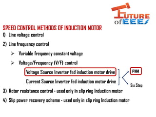
- 1. SPEED CONTROL METHODS OF INDUCTION MOTOR 1) Line voltage control 2) Line frequency control Variable frequency constant voltage Voltage/Frequency (V/F) control Voltage Source Inverter fed induction motor drive Current Source Inverter fed induction motor drive 3) Rotor resistance control - used only in slip ring Induction motor 4) Slip power recovery scheme - used only in slip ring Induction motor Six Step PWM
- 2. VOLTAGE SOURCE INVERTER FED 3 PHASE IM (SINUSOIDAL PWM) HOW VOLTAGE (MAGNITUDE) & FREQUENCY CONTROL IS DONE USING PWM OPERATION ? S1 S3 S5 S2 S4 S6 VA0 VB0 VC0 A B C VA0, VB0 , VC0 = POLE VOLTAGES (You can directly control these pole voltage by controlling the gate voltages of IGBT switches!) For example: • When S1 (upper) turned ON then, VA0 +V/2 • When S2 (lower) turned ON then, VA0 - V/2 • When S3 (upper) turned ON then, VBO +V/2 • When S4 (lower) turned ON then, VBO -V/2 • When S5 (upper) turned ON then, VC0 +V/2 • When S5 (upper) turned ON then, VC0 -V/2 But in V/F control, what we need to control is “magnitude” & “frequency” of line voltages (VAB, VBC, VCA) VAB (0 DEG Phase shift) = VA0 – VB0 VBC (120 DEG Phase shift)= VB0 – VC0 VCA (240 DEG Phase shift)= VC0 – VA0 { If we control the pole voltages (by controlling the gate voltages of IGBTs switches), then it is possible to control the magnitude & frequency of line voltages 1st leg 2nd leg 3rd leg V/2 V/2 V 0V + - + -
- 3. HOW CONTROLLED GATE VOLTAGES ARE GENERATED IN PWM? Sinusoidal / Modulating signal Triangular/ Carrier Signal Comparators G1 (S1) [Upper] G2 (S2) [Lower] G3 (S3) [Upper] G5 (S5) [Upper] G4 (S4) [Lower] G6 (S6) [Lower] So that both upper & lower transistor will not turn ON @ the same time – So Short circuit will not happen! 0 degree 120 degree 240 degree 1st leg 2nd leg 3rd leg
- 4. Sin 1 Triang Sin 2 (120 degree) Sin 1 (o degree) Sin 3 (240 degree) Triang Comparators G1 (S1) G2 (S2) G3 (S3) G4 (S4) G5 (S5) G6 (S6) POWER CIRCUIT PWM CONTROL CIRCUIT GATE VOLTAGESG2 (S2) G1 (S1) G1(S1) VAO -V/2 -V/2 -V/2 + V/2 + V/2 Lets analyze how gate voltages are generated for single sinusoidal signal and triangular signal -- What we need to control is magnitude & frequency of line voltages ! T>S T>S T>SS>T S>T VAB = VA0 – VB0 G2 (S2) G2 (S2) So lets analyze for single line voltage VAB G1 G2 G3 G4 G5 G6
- 5. Sin 1 ( 0 degree) Sin 2 ( 120 degree) Triang VA0 VB0 VAB VAB = VA0 – VB0 HOW TO CONTROL MAGNITUDE OF LINE VOLTAGE VAB? HOW TO CONTROL THE FREQUENCY OF LINE VOLTAGE VAB? “f VAB = f Sin” For example, TO INCREASE THE FREQUNECY OF VAB YOU NEED TO INCREASE THE “FREQUENCY OF THE SINUSOIDAL SIGNALS” & VICE-VERSA TERMINNOLOGY 1 : CARRIER RATIO = ft/ fs fc = frequency of triangular signal fs = frequency of sinusoidal signals For example, TO INCREASE THE VOLTAGE VAB YOU NEED TO INCREASE THE “AMPLITUDE OF THE SINUSOIDAL SIGNAL” & VICE- VERSA TERMINNOLOGY 2 : MODULATION INDEX = As/ At Am = Amplitude of sinusoidal signal Ac= Amplitude of triangular signal NOTE : Pulses in each half cycle have different widths (central pulse is wider). Less harmonics (Fourier analysis) + V/2 + V/2 + V/2 + V/2 - V/2 - V/2 - V/2 - V/2 + V/2+ V/2+ V/2 - V/2 - V/2 - V/2 - V/2 + V + V - V
- 6. VSI (SIX STEP SWITCHING) DOWNLOAD (PPT & PDF) IN THE DESCRIPTION