Gear Quality Parameters
•Als PPTX, PDF herunterladen•
9 gefällt mir•7,880 views

The gear accuracy or quality may then be described by a single number that indicates how closely it complies with an appropriate acceptance standard.

Empfohlen
Weitere ähnliche Inhalte
Was ist angesagt?
Was ist angesagt? (20)
Ähnlich wie Gear Quality Parameters
Ähnlich wie Gear Quality Parameters (20)
Kürzlich hochgeladen
Kürzlich hochgeladen (20)
Gear Quality Parameters
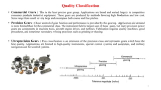
- 1. Quality Classification • Commercial Gears : This is the least precise gear group. Applications are broad and varied, largely in competitive consumer products industrial equipment. These gears are produced by methods favoring high Production and low cost. Sizes range from small to very large and encompass both coarse and fine pitches. • Precision Gears : Closer control of gear function and performance is provided by this gearing. Application and demand is more limited than for the commercial class. The instrument field is largest user of these gears, but many precision power gears are components in machine tools, aircraft engine drives, and turbines. Fabrication requires quality machines, good procedures, and sometimes secondary refining processes such as grinding or shaving. • Ultraprecision Gears : This classification is an extension of the precision class and represents gears which have the best quality. Applications are limited to high-quality instruments, special control systems and computers, and military navigation and fire control systems. 1
- 2. Scheme of the quality parameters for cylindrical gear drives 2
- 3. Scheme of the quality parameters for cylindrical gear drives 3
- 4. Scheme of the quality parameters for cylindrical gear drives 4
- 5. Individual Working Quality Parameters In the working test gear teeth are mated with counter gear teeth and the combined effects of their individual geometrical deviations (individual errors) on the working action are determined as composite and cumulative errors. These can be assigned to one of the gears (the test gear) if the gear used as the mating gear is a master gear with deviations which are negligibIy small compared with the deviations of the test gear. It is common to use master gears with a quality at least three grades higher than the specified quality of the gear under test. If the deviations of the matine gear are not negligibly small (e.g. when the working test is performed with two transmission gears) the composite and cumulative errorş can only be assigned jointly to the gear pair. Composite and Cumulative Errors Centre distance a set to a fixed value. Single-flank engagement of the right flanks left flanks through torque constraint, Tangential composite errors = relative deviations of angle of rotation compared with the corresponding zero-deviation angular settings brought about by a reference measuring system. The centre distance is established through the action of a load acting coaxially with the line of centres and varies with the rotation of gear and mating gear. Double-flank engagement. Radial composite errors = center distance alterations. 5
- 6. Gear metrology refers to a special branch of metrology as relevant to gear accuracy, gear measurement techniques, and instruments. It usually requires specialized training and expertise to perform adequately. The main objectives of gear accuracy measurement are as follows: • Check the compatibility/level of gear accuracy with the specified tolerances before actual use, i.e., to assure required accuracy and quality. • Provide an insight into the performance of the gear manufacturing process including the setup of the gear making machine tools, condition of the gear cutting tools, machine tool control, and basic machining practices. • Determine the distortions caused by possible heat treatment to facilitate corrective action. • Minimize overall cost of manufacture by controlling rejection and scrapping. Measurement of Gear Accuracy Dimensional or macro geometry parameters. Micro geometry parameters. Gear Accuracy Gear accuracy refers to how closely its main geometric features resemble the theoretical design. Significant gear metrology parameters that are used to quantify gear accuracy may be divided into two major classes. The gear accuracy or quality may then be described by a single number that indicates how closely it complies with an appropriate acceptance standard. 6
- 7. Macro geometry parameters • It could be argued that the most significant macro geometry parameter of a gear is the tooth thickness. The tooth thickness is generally defined as the length of arc of the pitch circle between opposite faces of the same tooth, i.e., the thickness of a gear tooth along the pitch circle. Inaccuracy or errors in the micro- and macro geometry of a gear causes deviation from the ideal motion transmission conditions. In other words, the level and amount of deviations/errors in these parameters govern the functional performance of gears. 7
- 8. The various measurement methods can lead to slightly different tooth thickness results on any given gear. Variations in profile, pitch, helix, runout, and measurement location will have different effects depending on the measuring method employed, see Table. A precise prediction of how these variations impact the measurement result cannot be made. These variations cannot be separated from the measurement of tooth thickness. Therefore, a precise prediction of a measurement result from one method in relation to another method cannot be accurately made, although the different measuring methods will usually be reasonably consistent. 8
- 9. Micro geometry parameters The two major classes of microgeometry parameters are form parameters and location parameters. The former involves the shape of the teeth while the latter is associated with the actual teeth positioning. Significant form parameters are profile and lead, whereas pitch and runout are significant as far as location parameters are concerned. The number and magnitude of errors in these microgeometry parameters quantifies the quality of gears and may significantly affect their functional performance. Deformation and inaccurate clamping of the workpiece and tool, form defects of the cutter, vibration in the machine tool, errors in the machine tool axis, etc. are notable causes of errors in microgeometry parameters. In general, the assignment of gear quality grades are a function of the severity of the form and location errors. 9
- 10. 10
- 11. 11
- 12. 12
- 13. GEAR TOLERANCES AND STANDARDS In order to achieve a closer tolerance thereby ensuring high functional performance of the gears, gear fabrication should be more precise. This inevitably results in increased manufacturing cost. To achieve acceptable quality with tight tolerances, the gears have to be sent for post-finishing treatments, especially when fabricated by conventional processes. Various international standards exists that provide different quality level/grades for all types of gears by comparing their deviations from the tolerance specified as for each quality level. The quality grade is selected based upon the functional requirement of the gear. The manufacturing techniques and process is then chosen to achieve the tolerance specified for that grade. The American Gear Manufacturers Association (AGMA) standard is an example of such an international standard. They are developed by the AGMA and approved by the American National Standards Institute (ANSI). The current AGMA standards are as follows: 13
- 14. These standards cover tolerances and measuring methods. These are the current new standards that replaced the older standards ANSI/AGMA 2000- A88 (for spur and helical gears), and AGMA 390.3a (for bevel and worm gears). Other important international standards are also widely used. These include the German standards DIN 3962 and 3963 for spur and helical gears and DIN 3965 for bevel gears ; Japanese standards JIS B 1702 for spur and helical gears; and JIS 1704 for bevel gears ; International Standards Organization ISO 1328 , British standards BS 436. Quality is the characteristic properties of a gear distinguishing the nature of its manufacturing tolerances. Variation is the measured plus or minus change from the specified value, see below figure. Gear quality For a description of the application of gear tooth quality, 14
- 15. 15 Tolerance is the amount by which a specific dimensions is permitted to vary. The tolerance is the difference between the maximum and minimum limits and is an absolute value without sign, see below figure. Allowable variation is the permissible plus or minus deviation from the specified value, see side figure.
- 16. The manufacturer or the purchaser may wish to measure one or more of the geometric features of a gear to verify its accuracy grade. A gear which is specified to an AGMA accuracy grade must meet all the individual tolerance requirements applicable to the particular accuracy grade and size as noted in tables. 16
- 17. 17 • Certain necessary information should be provided to the operator(s) of the measuring equipment. The information required will vary depending on the type of measurement(s) required. • Most measurement processes require basic gear and blank data, number of teeth, pitch, pressure angle, helix angle, tooth size, outside diameter, root diameter, facewidth, design profile, design helix, etc. • Certain measuring tasks require additional information. For exampleı to measure profile, the profile control diameter and start of tip break must be provided. • With mechanical measuring equipment, additional information may be required: base circle diameter (radius), base helix angle, sine bar setting, etc, • The design engineer or engineering department should be responsible for supplying this minimum required inspection information to those performing the measurements. Required Inspection Information 1. Analytical inspection or measurement 1.1 Macro geometry Measurement 1.2 Micro geometry Measurement 1.2.1 Profile and Lead Measurement 1.2.2 Pitch and Runout Measurement 2. Functional inspection or measurement 2.1 Double-Flank Inspection 2.2 Single-Flank Inspection MEASUREMENT OF GEAR ACCURACY Essentially, there are two major classes of gear accuracy measurement
- 18. • Analytical gear inspection is used by gear manufacturers to determine if a gear meets the geometric specifications as described by a set of appropriate dimensions. • The results of an analytical inspection may point toward the source of a problem in the gear machining process. From a diagnostic standpoint, the analytical inspection can illustrate the extent of error that would be attributed individually to the various gear tooth parameters. • The parameters commonly checked by analytical gear inspection are profile error, lead error, pitch error, runout, and tooth thickness variation. This method does not detect defects (errors) such as burrs or nicks. 1 Analytical Gear Inspection 18
- 19. Span measurement using a disc micrometer 1.1 Macro geometry Measurement Four different techniques are commonly used to inspect the tooth thickness. These are measurement of the chordal thickness; over balls, pins or wires measurement; span measurement; Measuring blocks . 19
- 20. 1.2 Micro geometry Measurement There are mainly two major categories of instruments used for analytical inspection of errors in microgeometry of gears. The first is traditional Mechanical generative instruments, and the second is computer numerical control (CNC) instruments or coordinate measuring machines (CMM). Measuring objects in gear metrology and CNC-measuring device Universal gear measuring instruments (GMI) Gears are measured using CMMs or special mechanically or CNC-controlled gear measuring instruments (GMI). The devices differ with respect to the methods of measurement applied, the measurement strategy and the software used for the evaluation of the measured data. (A) CNC gear tester (WENZEL GearTec GmbH-Germany, Gear Metrology Machine at IIT Indore-India) and (B) accuracy inspection of external helical micro gear. 20
- 21. CMMs for gear measurements Very soon after introducing CMMs to industrial production it was realized that they were versatile enough to inspect such complicated objects as involute and bevel gears, screws, worms and even gear cutting tools like hobs. Being able to automate gear inspection using a CMM, a more flexible and relatively low-cost piece of equipment, brings the ability to do gear inspection to almost any shop that needs it. The other benefit is that many shops own an automatic CMM anyway, which means that gear inspection brings a new capability to an existing tool. 21
- 22. 1.2.1 Profile and Lead Measurement In practice, the gears are mounted on a shaft or fixtures and are mounted vertically between centers or accommodated in a rotating chuck affixed to the measurement table. A single measuring probe is used for both profile and lead measurement. The position of probe during measurement of microgeometry parameters (A) profile measurement, (B) lead measurement, and (C) pitch and runout measurement The machine compares the actual gear profile to the reference profile created against the gear specifications and may record the deviation graphically on a chart. 22
- 23. 1.2.2 Pitch and Runout Measurement • For measurement of pitch and runout, the probe is initially brought into contact with any tooth flank on the reference circle diameter point at mid face. • This initial flank is considered as the datum tooth flank. • The probe is then retracted from the tooth space, and the gear is indexed by an angle as appropriate for one tooth or pitch. • The probe then moves back into the reference circle diameter of the next tooth flank, and its location is recorded. • This process is repeated for a full rotation. The same procedure is conducted simultaneously for the opposite tooth flanks. Gear runout may also be inferred from these measurements. Radial runout test by means of CMM or GMI; a) Testing with rotating table, b) Testing without rotating table Pitch inspection by direct angular measurement 23
- 24. 2. Functional inspection or measurement Functional or composite gear inspection is a qualitative method of evaluating gear accuracy where the main objective is to compare a gear to the required specifications as provided by a reference gear. Essentially, the results of functional gear inspection reveals if a gear will work as intended. This method involves rolling two gears of the same specification together (where one is a master or reference gear and other is a work gear whose quality is to be evaluated) and measuring the resultant motion to determine composite error, tooth-to-tooth error, transmission error, etc. The gears can also be tested in pairs instead of using a master gear. Functional inspection may be subdivided into two basic types: A double flank tester in tight mesh Schematic representation the basic operational principle of a single-flank inspection machine. 24
- 25. The major differences between these two methods are as follows : • Single-flank inspection implies that only one flank is in contact during gear rolling, whereas in double-flank inspection, rolling occurs such that both flanks (right and left flanks) are in contact. • Double-flank inspection allows for center distance variation (therefore, also referred to as the “variable center distance method”), whereas in single-flank inspection, the center distance remains fixed (therefore also known as “fixed center distance method”). • Single-flank inspection evaluates transmission errors whereas double flank inspection cannot detect angular tooth position defects and thus cannot evaluate transmission errors. • Double-flank gear roll testers are usually manually operated and thus relatively inexpensive. 25
- 26. 2.1 Double-Flank Inspection In double-flank inspection, the gears are rolled closely meshed such that there is double-flank contact. Therefore no backlash. It presents a schematic of double-flank inspection along with an example of a typical double-flank roll tester. (A) Schematic of the double-flank inspection technique and (B) example of a typical double-flank type roll tester. 26
- 27. Total composite error as shown in the chart is a consequence of full rotation, while rotation only through one pitch gives tooth-to- tooth error. The total composite error is the difference between the highest and lowest points on the graph or between the maximum and minimum readings on the dial indicator during one rotation cycle of the test gear. This includes effects of profile and helix variation, pitch errors, and runout. The tooth-to-tooth error is defined as the greatest deviation within a single circular tooth pitch. It shows the worst tooth on the entire gear. The test gear is rejected if the total composite variation is greater than the allowable total composite tolerance as defined during gear design. Double-flank inspection does not provide information regarding accumulated pitch variation or specific tooth profile characteristics. Graphical representation of errors in gear quality obtained by a double-flank tester. 27
- 28. 2.2 Single-Flank Inspection The single-flank inspection method can evaluate all elements of gear quality, such as profile conjugacy (closely related to typical gear noise), adjacent pitch variation, accumulated pitch variation, and runout except lead (tooth alignment) or helix deviation. Moreover, the transmission error may be directly measured. Schematic representation the basic operational principle of a single-flank inspection machine. 28
- 29. Phase differences of less than one arc-second can easily be detected by this method. The waveform or curve displayed in this chart is for one revolution of a test gear. This curve is known as a “total transmission error curve” and composed of various quality parameters such as effective profile error, burr amplitude, adjacent pitch error, accumulated pitch error, tooth-to-tooth composite error, and total composite error. The total composite error is the difference between the highest and lowest points on the graph within one revolution of the test gear and includes the effect of a portion of profile error and accumulated pitch error. The tooth-to-tooth error is the variation in transmission error at the tooth meshing frequencies and mainly the consequence of profile errors and single pitch errors. These are important for the evaluation of gear noise. Single-flank inspection is usually conducted at relatively low loads. Typical output of a single-flank tester for evaluation of gear quality. 29
- 30. In particular, what you should do when you measured certain errors during the hobbing process. 30
- 31. 31
- 32. 32
- 33. 33
- 34. 34
- 35. 35
- 36. 36
- 37. 37
- 38. Errors occur outside of the analyzed area. Errors can occur between the measured teeth. Special Situations : Burrs Improper Undercut Short Involute Broaching Tears 38
- 39. 39
- 40. 40
- 41. 41
- 42. 42
- 43. 43
- 45. 45
- 46. 46
- 47. 47
- 48. 48
- 49. 49
- 50. 50
- 51. 51
- 52. 52
- 53. NEW MEASURING METHODS For modern numerically controlled (NC) measuring devices three major difficulties and trends are opposed to the historical probing and evaluation along prescribed section lines. Firstly, the correct evaluation of measured flanks requires ideally mounted gears or a numerical alignment prior to flank probing in order to "hit" the standardized profile and helix (lead) lines exactly. These requirements can only partially be fulfilled by CMMs, applying numerical alignment by means of geometric elements, or by specialized gear measuring devices, using Mechanical alignment with adapted clamping devices. Thus, errors inevitably occur during evaluation. Secondly, new optical measuring devices like stripe pattern projection or holographic systems can obtain several 10 000 points up to more than 200 000 points per flank within a few seconds, all containing valuable information about the actual gear flank. An evaluation strictly following the valid standards of gear metrology has to ignore the major part of this information. Thirdly, modern gear drives require more and more complex flank modifications (lead, crowning, twist, tip and root relief, k- charts, protuberance etc.), leading to a confusing increase of evaluation rules, conditions and exceptions. Therefore, a clear tendency towards a geometry description via a set (grid) of nominal points including their normal directions can be recognized. This type of nominal description covering the whole flank (instead of only one profile and one lead line) is already common for bevel gears and several gear tools (hobs, honing and grinding tools. 53
- 54. Structure of the system of Accuracy ISO system of accuracy (ISO 1328) comprises 13 accuracy grades of which grade 0 is the highest and grade 12 is the lowest degree of accuracy. The DIN (3961) gear tooth tolerance system contains 12 gear tooth qualities. The finer qualitities are intended for master gears and special requirement. The ANSI/AGMA 2015 classification system is an alpha numeric code which contains two items, accuracy grade and prefix. The AGMA classification number shall consist of a prefix letter ‘‘A’’ identifying the tolerance source, and an accuracy grade identifying the specific tolerances. Quality requirements for various gear applications in terms of DIN &AGMA standards 54
- 55. New ANSI/AGMA Accuracy Standards for Gears Correlation of existing ISO and new AGMA gear accuracy documents. The New Accuracy Grade System AGMA 2000-A88 includes 13 quality classes numbered Q3 through Q15, in order of increasing precision. ANSI/AGMA 2015-1-A01 provides 10 accuracy grades numbered A2 through A11, in order of decreasing precision. In other words, the smaller the accuracy grade number in the new standard, the smaller the tolerances. While this is the opposite of the structure of 2000-A88, it follows the convention of all other major gear accuracy standards. It is important to understand the fundamental changes coming with the new AGMA standards. Given the approaching withdrawal of AGMA 2000-A88, an increasing number of gears will be specified according to the replacement documents. It is possibly more important to understand the increasing AGMA focus on ISO standards development. It appears that, in coming days, ISO documents will provide the default specifications. 55
- 56. The new edition of ISO 1328 introduces changes in the range of calculating of the tolerance values. Moreover, it gives many significant details on considerations for elemental measurements such as datum axis, direction of measurement, direction of tolerance, measurement diameter, data filtering, data density, required measuring practices The new edition introduces guidelines on minimum set of parameters to be measured Table. Among the parameters there are two not considered in the standard, i.e. s –tooth thickness and cp –contact pattern. Parameters to be measured 56
- 57. 57
- 58. 58
- 59. References DIN 3960 – Concepts and parameters associated with Cylindrical gears and Cylindrical gear pairs with involute teeth DIN 3961 - Tolerances for Cylindrical Gear Teeth DIN 3962 – Part 1- Tolerances for Cylindrical Gear Teeth/ Tolerances for Deviation of Individual Parameters DIN 3962 – Part 2 -Tolerances for Cylindrical Gear Teeth /Tolerances for Tooth Trace Deviations Quality Characteristics of Gearing - D. Babichev and M. Storchak – July 2018 Gear Inspection: Troubleshooting Tips - Dennis Gimpert - https://gearsolutions.com/archives/?magazine=2007-02 BS 436-4:1996 / ISO 1328-1:1995 -Part 4: Definitions and allowable values of deviations relevant to corresponding flanks of gear teeth ISO 1328-Part 1 –Definitions and allowable values of deviations relevant to corresponding flanks of gear teeth ISO 1328-Part 2 –Definitions and allowable values of deviations relevant to radial composite and runout information AGMA Webinar Series / Analytical Gear Chart Interpretation: Solving Manufacturing Problems/ Dwight Smith President, Cole Mfg. Systems, Inc. June 7, 2012 ANSI/AGMA 2015- 1-A01 / Accuracy Classification System - Tangential Measurements for Cylindrical Gears ANSI/AGMA 1012-G05-Gear Nomenclature, Definition of Terms with Symbols AGMA 915-1-A02 / Inspection Practices- Part 1: Cylindrical Gears- Tangential Measurements Gear Metrology / G. Goch Measurement of Gear Accuracy / Chapter 7 / Advanced Gear Manufacturing and Finishing book Comparison ISO standards 1328 1:1995 and 1328 1:2013 / Mirosław WOJTYŁA , Władysław JAKUBIEC , Wojciech PŁOWUCHA New ANSI/AGMA Accuracy Standards for Gears / Edward Lawson Gear Quality Parameters and Tooth Flank Modification / http://www.wenzel-group.com/ Near-Net Shape Manufacturing of Miniature Spur Gears by Wire Spark Erosion Machining /Kapil Gupta, Neelesh Kumar Jain ANSI/AGMA 1012-G05-Gear Nomenclature, Definition of Terms with Symbols 59