
Empfohlen
Weitere ähnliche Inhalte
Was ist angesagt?
Was ist angesagt? (20)
Ähnlich wie Transformer
Ähnlich wie Transformer (20)
Kürzlich hochgeladen
Kürzlich hochgeladen (20)
Transformer
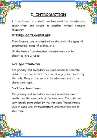
- 1. I. INTRODUCTION A transformer is a static machine used for transforming power from one circuit to another without changing frequency. II.TYPES OF TRANSFORMER: Transformers can be classified on the basis, like types of construction, types of cooling, etc. On the basis of construction, transformers can be classified into 2 types:- Core type transformer: The primary and secondary coils are wound on separate limbs of the core so that the core is largely surrounded by the coils. Many of the modern transformers are of the closed core type. Shell type transformer: The primary and secondary coils are wound one over another on the same limb of the iron core. The coils are very largely surrounded by the iron core. Transformers used in radio and TV transmitters and receivers are of shell type.
- 2. On the basis of purpose: STEP UP TRANSFORMER step-up transformer is the direct opposite of a step-down transformer. There are many turns on the secondary winding than in the primary winding in the step-up transformers. Thus, the voltage supplied in the secondary transformer is greater than the one supplied across the primary winding, Because of the principle of conservation of energy, the transformer converts low voltage, high- current to high voltage-low current. In other words, the voltage has been stepped up. STEP DOWN TRANSFORMER: In a step-down transformer is one who secondary windings are fewer than the primary windings. In other words, secondary voltage is less than the primary voltage transformer is designed to convert high-voltage, low- current power into a low-voltage, high current power and it is mainly used in domestic consumption.
- 3. III. Working principle of Transformer The working principle of transformer depends upon Faraday's law of electromagnetic induction. Actually, mutual induction between two or more winding is responsible for transformation action in an electrical transformer. According to these Faraday's laws, "Rate of change of flux linkage with respect to time is directly proportional to the induced EMF in a conductor or coil.
- 4. IV. THEORY Consider a situation when no load is connected to the secondary, i.e., its terminals are open. Let N1 and N2 be the number of turns in the primary and secondary respectively. Then, Induced emf in the primary coil, E1 =-N1d /dt Induced emf in the secondary coil, E2 =-N2d /dt Where is the magnetic flux linked with each turn of the primary or secondary at any instant. Thus E2/E1 =N2/N1 Let E be the emf applied to the primary .By Lenz’s law, self-induced emf E1 opposes E in the primary coil. Hence resultant emf in the primary = E-E1 This emf sends current I1, through the primary coil of resistance R. E-E1 = RI1 But R is very small, so the term RI1 can be neglected. Then E=E1 Thus E1 may be regarded as input emf and E2 as the output emf. E1/E2= Output/Input = N2/N1 The ratio of the number of turns in the secondary to that of the primary is called the turn’s ratio of the transformer.
- 5. CURRENTS İN PRIMARY AND SECONDARY COIL Assuming the transformer to be ideal one so that there are no energy losses, then no energy losses, then Input powers output power or E1I1 = E2I2, where I1, and I2 are the currents in the primary and secondary, respectively Hence I1/I2 = E2/E1 = N2/N1 thus the step up transformer steps up the voltage, but steps down the current exactly in the same ratio. Similarly, a step down transformer steps down the current exactly in the same ratio. The efficiency of a transformer is defined as η = [Power output/ Power input] X 100% the efficiency of real transformers is high [90-99] % though not 100%
- 6. IV. CONSTRUCTIONAL PARTS OF A TRANSFORMER These are the basic components of a transformer: Laminated core Windings Insulating materials Transformer oil Tap changer Breather Cooling tubes Buchholz Relay Explosion vent A transformer essentially consists of two coils of insulated copper wire having different number of turns and wound on the same soft iron core. The coil P to which electric energy is supplied is called the primary and the coil from which energy is drawn or output is obtained is called the secondary. To prevent energy losses due to eddy currents a laminated iron the entire magnetic flux due to the current in the primary coil practically remains in the iron core and hence passes fully through the secondary. This also prevents the stray current being generated in the conductor lying around and the consequent power loss.
- 7. ENERGY LOSSES IN TRANSFORMER The main causes for energy loss in transformers are as follows: 1.Copper loss: Some energy is lost due to heating of copper wires used in the primary and secondary windings. This power loss (-I'R) can be minimized by using thick copper wires of low resistance. 2. Eddy current: The alternating magnetic flux induces eddy currents in the iron core which leads to some energy in the form of heat. This loss can be reduced by using laminated iron core. 3. Hysteresis loss: The alternating current carries the iron core through cycles of magnetization and demagnetization. Work is done in each of these cycles and is lost as heat. This is called hysteresis loss and can be minimized by using core material having narrow hysteresis loop. 4.Flux Leakage: The magnetic flux produced by the primary may not be fully associated with the secondary. Some of the flux may leak into the air. This loss can be minimized by winding primary and secondary coils over one another. 5. Humming Loss: In this case the transformer gives rise to humming sound by a phenomenon called magnetosriction.
- 8. V. Uses of transformer 1. Small transformers are used in radio receivers, Telephones, loud speakers, etc. 2. In voltage regulators for TV, refrigerators, air conditioners, computers, etc. 3. In stabilized power supplies. 4. A step down transformer is used for obtaining large current for electric welding. 5. A step down transformer is used in induction furnace for melting metals. 6. A step up transformer is used for the production of X- rays. VI. CONCLUSION Thus the above discussed project work gives the detailed study of construction, working, uses of transformers.
- 9. CERTIFICATE -1 This to certify that PRATYUSH KUMAR OF CLASS XII-C has successfully completed his project entitled ‘POWER TRANSFORMER’ under our guidance and supervision during academic year 2019-2020. Sign of Internal Sign of External
- 10. CERTIFICATE-2 This is to certify that PRATYUSH KUMAR of : class XII-C has successfully completed his project entitled 'POWER TRANSFORMER : under our guidance and supervision during academic year 2019-2020 Dr. BK MISHRA (Principal) Delhi Public School Nalco Nagar, Angul
- 11. ACKNOWLEDGEMENT I express deep sense of gratitude to my guide Mrs K.Panda, physics teacher and Mr N.R. Pattnaik lab asst. For their kind guidance, supervision and encouragement for the timely and successful completion PRATYUSH KUMAR
- 12. CONTENTS Introduction Types of transformers Working principle of transformers Constructional parts of transformers Theory Uses of transformers
- 13. conclusion BIBLIOGRAPHY www.google.com www.wikipedia.com NCERT CLASS 12th physics book Physics reference book by S.L.ARORA