
Empfohlen
Weitere ähnliche Inhalte
Was ist angesagt?
Was ist angesagt? (20)
Ähnlich wie Safety features of anaesthesia machine
Ähnlich wie Safety features of anaesthesia machine (20)
Kürzlich hochgeladen
Kürzlich hochgeladen (20)
Safety features of anaesthesia machine
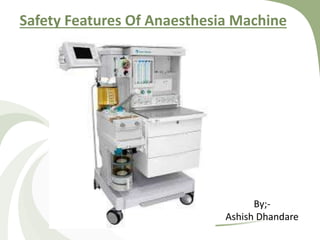
- 1. Safety Features Of Anaesthesia Machine By;- Ashish Dhandare
- 2. Basic design :- • 3 Pneumatic components :- 1) High Pressure System, 2) Intermediate Pressure System, 3) Low Pressure System. Each & every component – Safety features are incorporated.
- 4. High Pressure System :- A) Hanger Yoke Assembly :- Gate Nipple Washer Retaining screw Yoke plug
- 5. 1) Pin-Index System :- - Prevents wrong cylinder attachment. - Pesence & Integrity of pins should be checked. 2) Filter :- Prevents dust & foreign particles from entering. 3) Unidirectional valve :- - Prevents backflow into the cylinder when cylinder pressure falls below the pressure inside the machine.
- 6. B) Colour coding :- Colour coding of cylinders used for same gas in machine. caps, hoses, flow control knobs, Pressure gauges.
- 7. C) Pressure regulator :- 1) Separate regulator for each gas. 2) Cylinder output reduced to 45 psig Pipeline output reduced to 50-55 psig.
- 8. Intermediate Pressure System :- A) Pipeline inlet connections :- 1) Fitted with threaded non-interchangeable DISS 2) Colour coded for gases.
- 9. B) Pipeline pressure gauge :- • Colour coded for each gas. • Present on the pipeline side of the unidirectional valve. If present on the machine side – will show cylinder pressures. Thus wont read 0 if pipeline supply fails. C) Piping inside the machine :- Able to withstand 4 times the intended service pressure.
- 10. C) Oxygen Failure Safety Device / Fail Safe Valve / N2O Shut off Valve :- ASTM Stds require that;- Whenever O2 supply pressure falls below manufacturer specified min pressure, the delivered O2 conc at the CGO should not fall below 19%. • If O2 pressure falls – N2O pressure falls proportionately. • If O2 supply fails – N2O is shut off.
- 11. How to check O2 fail safe valve :- 1) Switch on the flows of N2O & O2 in flowmeters. 2) Disconnect O2 pipeline/ Close the cylinder valve. 3) N2O flow indicators falls to 0 even before the O2 indicator falls D) O2 Failure Safety Alarm :- Alarm wil set of when O2 pressures fall below specified minimum. (Usually 30 psig) Not possible to silence unless the pressure is restored. C) & D) – They are pressure dependant not flow.
- 12. E) Gas selctor Switch :- Present in some machines only. Prevents Air & N2O from being used together.
- 13. F) 2nd Stage Pressure regulator :- • Present only in some machines. • Reduces pressures further to;- O2 – 14 psi N2O – 26 psi • Provides a stable pressure to flowmeters i.c.o. pipeline pressure fluctuation.
- 14. G) O2 Flush :-
- 15. • Delivers high flows (35-75 L/min) at intermediate pressures. •Can be activated even if the master switch is off. • Inapproapriate & long activation – Barotrauma & Awareness d/to dilution Thus designed as;- “Single purpose, self closing device & recessed” • Usually reccessed/ placed in a collar – to prevent accidental activation.
- 16. H) Flow Control Knob :-
- 17. • Only 1 flow control for each gas. • adjacent to / a/w the corresponding gas flowmeter. • Color coded for each gas. • Different size, consistency & position. eg :- O2 – larger & fluted & on the right side/ downstream.
- 18. Low Pressure System :- A) Flowmeter assembly :- • 1) Stops @ full ON & OFF pos. Stop at full on pos – at top ↓ a) Prevents escape of indicator from tube to common manifold. b) prevents blockade of common manifold by the stop. c) prevents indicator from ascending to the top where it cant be seen clearly. Stop collar to flowmeter knob – prevents damage to seat by pin when tightened.
- 19. • 2) Different tubes for different gases – vary in diameter & calibration. • 3) Tubes made leak proof by “O-rings” (Neoprene washers) at both the ends. • 4) Tubes coated with anti-static coating on both surfaces ↓ prevents indiactor from sticking. • 5) Made of glass – transparent material ↓ indicator clearly visible throughout the tube.
- 20. Flowmeter arrangement :- O2 always downstream to all.
- 21. B) Hypoxia Prevention Devices :- 1)Mandatory Min O2 Flow (MMOF):- A MMOF – 50-250 ml/min – must as soon as the master switch is turned on. O2 flow – cant be reduced below that. Some machines – Alarms when O2 flow falls below MMOF. 2) Min O2 Ratio :- ASTM Stds require that; A Min O2 ratio/ Min O2 conc of 21% in the FGF at CGO. 2 types of linkages to achieve this.
- 22. a) Mechanical Linkage – Link 25 Proportionating System :- • Mechanical Linking of O2 & N2O. O2 – 14 tooth sprocket, & N2O – 29 tooth sprocket Connected by metal chain. • Both knobs turn together – to maintain min 25% O2 conc. • Diadvantage – if 3rd gas is administered (eg He) – hypoxic mixture may be delivered. Tooth sprockets interconnected by chain.
- 23. b) Electronic Linkage :- • An electronic proportionating valve ↓ maintains min 25% O2 conc in FGF. • A computer continuously calculates the N2O flow for the given O2 flow ↓ If higher N2O flow & O2 conc <25% ↓ Electronic proportionating valve automatically reduces N2O flow 3) Alarms :- set off when O2:N2O falls below a preset value.
- 24. C) Unidirectional check valve :- • Location :- Downsream to vapourisers Upstream to the point where O2 flush meets FGF. • Positive pressures generated within the ckt.s (eg – during controlled ventilation, when O2 flush is used) ↓ if transferred back to the machine ↓ dilution of volatile agents & interfere with the outflow through flowmeters & vapourisers. • Prevents +ve pressures within the ckt.s to be transferred to the machine. •Disadvantage :- Leaks upstream to the valve cant be detected.
- 25. D) Pressure Relief Devices :- • Location :- Downstream to the unidirectional valve Upstream to the point where O2 flush joins FGF. • To protect machine from high pressures. Opens & vents gases to atmosphere when preset pressure is exceeded. • Disadvantage :- Limits ability of the machine to provide adequate pressures ↓ Jet ventilation cant be provided
- 26. E) Common Gas Outlet (CGO) :- • ASTM stds require that;- It should be difficult to accidently disconnect the delivery hose from the CGO. ↓ Thus fitted with std 15mm female slip joint fitting with 22mm coaxial male connector. • Some machines have 2 CGOs ↓ ASTM stds require that;- Only 1 CGO must be functional at a time.
- 27. THANK YOU