Erection Checklist for Solar Inverters, Solar Transformers & Solar String Combiner Box
•
11 gefällt mir•9,657 views

The documents serves as a handy guide to erecting & commissioning Solar Inverters, Solar Transformers & Solar String Combiner Box.

Empfohlen
Empfohlen
Weitere ähnliche Inhalte
Was ist angesagt?
Was ist angesagt? (20)
Andere mochten auch
Andere mochten auch (20)
Ähnlich wie Erection Checklist for Solar Inverters, Solar Transformers & Solar String Combiner Box
Ähnlich wie Erection Checklist for Solar Inverters, Solar Transformers & Solar String Combiner Box (18)
Mehr von Gensol Engineering Limited
Mehr von Gensol Engineering Limited (20)
Kürzlich hochgeladen
Kürzlich hochgeladen (20)
Erection Checklist for Solar Inverters, Solar Transformers & Solar String Combiner Box
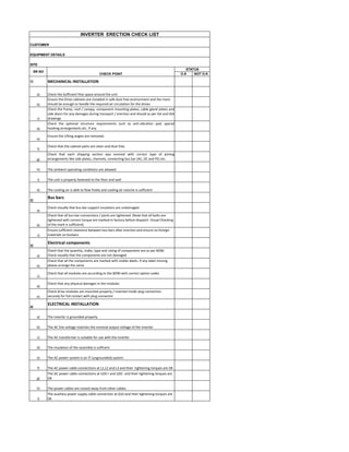
- 1. O.K NOT O.K 1) MECHANICAL INSTALLATION a) Check the Sufficient free space around the unit b) Ensure the Drive cabinets are installed in safe dust free environment and the room should be enough to handle the required air circulation for the drives c) Check the frame, roof / canopy, component mounting plates, cable gland plates and side doors for any damages during transport / erection and should as per GA and IGA drawings d) Check the optional structure requirements such as anti-vibration pad, special hooking arrangements etc. if any e) Ensure the Lifting angles are removed. f) Check that the cabinet parts are clean and dust free. g) Check that each shipping section was erected with correct type of joining arrangements like side plates, channels, connecting bus bar (AC, DC and PE) etc. h) The ambient operating conditions are allowed i) The unit is properly fastened to the floor and wall k) The cooling air is able to flow freely and cooling air volume is sufficient 2) Bus bars a) Check visually that bus bar support insulators are undamaged. b) Check that all bus bar connections / joints are tightened. (Note that all bolts are tightened with correct torque are marked in factory before dispatch. Visual Checking of the mark is sufficient) c) Ensure sufficient clearance between bus bars after erection and ensure no foreign materials on busbars 3) Electrical components a) Check that the quantity, make, type and rating of components are as per BOM. Check visually that the components are not damaged b) Check that all the components are marked with visible labels. If any label missing please arrange the same c) Check that all modules are according to the BOM with correct option codes d) Check that any physical damages in the modules e) Check drive modules are mounted properly / inserted inside plug connectors securely for full contact with plug connector 4) ELECTRICAL INSTALLATION a) The inverter is grounded properly b) The AC line voltage matches the nominal output voltage of the inverter c) The AC transformer is suitable for use with the inverter d) The insulation of the assembly is sufficent e) The AC power system is an IT (ungrounded) system f) The AC power cable connections at L1,L2 and L3 and their tightening torques are OK g) The DC power cable connections at UDC+ and UDC- and their tightening torques are OK h) The power cables are routed away from other cables i) The auxiliary power supply cable connection at Q10 and their tightening torques are Ok CUSTOMER EQUIPMENT DETAILS SITE INVERTER ERECTION CHECK LIST SR NO CHECK POINT STATUS
- 2. k) The external control connections to the inverter are OK (including emergency stop, feildbus etc.) l) The cable connections at the junction box (option+K479) and their tightening torque are OK m) The EMC filter (option +E216) is correctly installed,if present n) There are no tools, foreign objects or dust from drilling inside the modules or the cabinet o) All shrouds and covers are in place 5) Cabling and wiring a) Check that Field (Customer side) analog signal cables like PT100 are wired with shielded cable. Also check those shields are properly earthed at one end. Earth Loop should be avoided b) Check that all Field cables enough in length and stress free. The cables should be with proper cable gland and tightened with Gland plate c) Check that all fiber optic cables are not damaged, connectors not to be broken, not routed against sharp edges or bare live parts and bending radius of the FO cables is bigger than 35 mm. d) Check, by gentle pulling the cables, that their connections to component terminals are tight enough e) Check that short links on TB’s and loop chaining are done according to scheme 6) Earthing and Mechanical Operating Tests a) Check that the panels are dual earthed. Welding of earth bars with panel is not recommended. (Please note there may be a separate Power and Electronic earthing practice in some plants) b) Check the functionality of all switches by closing and opening them c) Check that fuses are placed tightly in the middle of the fuse socket / fuse base. d) Check that the doors for open and close without rubbing or noise when open and close. e) Check the door defeat function. When fuse switch or disconnecting switch is closed, the cabinet door cannot be opened. 7) Start-Up Preparation a) Make sure that the panel is safe to connect voltage b) Keep all switches and breakers of the panel in OFF position and do the necessary short links if required c) Ensure that nobody is working on the unit or circuits that are associated to the panel to be test like inter panels, shipping section, motor etc. d) Keep all cabinet doors in close before power up e) Ensure auxiliary voltages available for backcharging and control testing f) Status of Grid voltage availability and readiness for energising g) Status of panel earthing and earth pits h) Status of DC power connections readiness Consultant Engineer Client Engineer Acceptance Date Contractor Engineer
- 3. O.K NOT O.K 1) AVAILABILITY OF DOCUMENTATION a) Erection drawings including OGA b) Erection / Maintenance Manual c) Transport packing list 2) RECEIPT OF TRANSFORMER a) Externally inspected damage (if any) b) Gas pressure on receipt (Where applicable) c) Oil level (in case of oil filled transformer) d) Unit correctly positioned 3) RECEIPT OF ACCESSORIES a) All materials stored correctly b) Packing Cases inspected, damage if any c) Marshalling box inspected, damage if any d) Control panels (RTCC)inspected damage if any e) Materials received corresponded to Advise note f) Any shortages / wrong supply g) Materials comply with shipping specification h) Remark (if any) 4) ERECTION a) Transport rollers mounted b) Conservator mounted c) Buchholz relay and oil surge relay mounted (arrow marked should be towards conservator) d) Breather mounted and duly charged e) HV Bushings mounted f) LV Bushing mounted Sr. No. Check Point Status TRANSFORMER ERECTION CHECK LIST Customer:- Equipment Details:- Site:-
- 4. g) Tertiary Bushing mounted (if applicable) h) HV neutral Bushing mounted i) LV Neutral Bushing mounted j) Bushing installed at correct angles k) Diaphragm checked l) MOLG mounted m) Radiator mounted n) Fans mounted o) Pressure Relief valves mounted p) Alignment of all pipe work q) OLTC Conservator mounted r) Heat Exchangers assembled with pipe work s) Topping up of transformer oil t) Leakage observed after 24 hrs.(if any) u) Rating Diagram and identification plate fitted v) Control panel (RTCC) aligned w) Control panel (OLTC) aligned 4) OIL FILLING a) All bushing oil level b) Tap changer selector oil level c) Diverter switch oil level d) Auxiliary unit oil level e) Radiator, Headers oil filled f) Transformer / OLTC Conservator oil tight g) Complete transformer oil tight h) All air release plug vented i) Valves in service position j) All drain / filter valves blanked 5) MULTICORE CABLE a) All tray work adequately secured
- 5. b) All cables adequately tied/clipped back to tray c) Cables glaned correctly 6) BREATHERS a) Transformer silica gel breather satisfactory b) Tap changer silica gel breather satisfactory c) Dry breather correctly installed 7) FANS a) Fans rotate freely & quickly b) Pumps installed for correct c) Flow indication visible 8) CONTROL PANELS a) Cable termination & Glanning 9) Cleaning and touch up of painting Consultant Engineer Client Engineer DateAcceptance Contractor Engineer
- 6. O.K NOT O.K 1) SCB Assembly / Installation a) Mounting Structure's verticality, alignment, GI coating b) Casting of mounting structure and pile cap above G.L c) Clerance between bottom of SMB and G.L. d) Overall visual aspect (damages, Scratches) e) Box Fixation and assembly d) SCB allocation (ID Vs allocation) f) Cleaning of the interior of the panel box g) Labelling/Numeration of SCB as per drawing 2) Equipment a) Input NHI Fuse status (Input Fuses) b) Surge Arrestor Flag c) DC switch operational 3) Electrical Connections a) Ground connectivity to GI strip, cable and connections b) DC output, cable and connections c) String input, cable and connections d) Gland tighting e) Protection against direct contact f) All connection tightness g) Cable Labelling (Inputs, Outputs, Auxiliary, communication cables) 4) Documentation a) SCB's SLD & String Layout Client Engineer Acceptance Date Contractor Engineer Consultant Engineer Sr. No. Check Point Status SCB ERECTION CHECK LIST Customer:- Equipment Details:- Site:-