The document discusses the MPU6050 motion sensor. It contains a 3-axis gyroscope, 3-axis accelerometer, temperature sensor, and digital motion processor. The MPU6050 communicates via I2C and provides orientation and motion data to applications like robotics, drones, and aircraft.
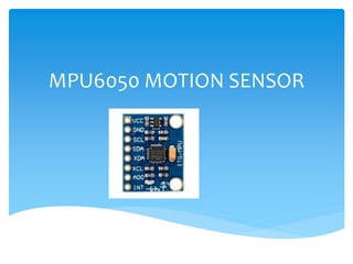
2. GY-521 is a breakout board for the MPU-6050
which is a microelectrical mechanical system
MPU6050 is the first integrated 6-axis Motion
Tracking device that combines a 3-axis gyroscope 3-
axis accelerometer,Temperature Sensor and
DMP(Digital Motion Processor) on a single ic.
DMP correlates the data from accelerometer and
gyroscope
Introduction
3. DMP can also use external 3rd party sensors such as
magnetometer
External sensors connect using 2nd I2C bus
MPU6050 sensor can communicate with the various
microcontroller using I2C interface
The MPU6050 is a 6-axis IMU sensor it will give 6
values in output
Three values from accelerometer and three from
Gyroscope.
Introduction
4. Accelerometer measures the Acceleration forces
exerted on the x,y,z axes.
Gyroscope measures the rotational movement of an
object over the axes x,y,z
Principle
5. Accelerometer is a sensor which can measure the
acceleration forces which are acting on it
When the force increases acceleration increases.
Accelerometer
6. Consider the sensor resting on a table. At rest there
is no force acting on the sensor? There fore all the
axes have to get zero readings.
But actually this is wrong. If there are no dynamic
forces are acting on the sensor also there is a static
force acting on it. That is the acceleration due to
gravity g .9.8m/s2
This is acting perpendicular to the sensor
Accelerometer
7. When you shake this sensor there are different values
across different axes.
If you shake the sensor faster values across the axes
are increases. If you shake slowly then the values
across the axes are decreases.
The micro crystals inside the sensors will produce raw
readings which are directly proportional to the forces
exerted on the sensor
Accelerometer
8. Gyroscope measures rotational movement of the object
across its axes.
Gyroscope in MPU-6050 is a ‘Mems Gyroscope”
MEMS=“Micro Electro Mechanical System”
Gyroscope
9. MEMS sensors produces a voltage when an axis is
rotated
Voltage is sampled with a 16-bit ADC
The unit in which how fast the object is rotating is
given by deg/sec in gyro.
Gyroscope will not affect the vibrational force acting
across the object.
Gyroscope
12. The gyroscope present in the MPU6050 can detect
the rotation about the axes x,y,z.
Coriolis effect causes a vibration when the gyros are
rotated about any of these axes.
These vibrations are picked up by the capacitor .
The signal produced is then amplified ,demodulated
and filtered to produce the voltage that is
proportional to the angular rate
Explanation
13. This voltage is then digitized using ADC’s
The Digital motion processor present on the sensor
offloads the computation of the motion-sensing
algorithm from the host computer.
DMP acquires data from all the sensors and stores the
computed values in its data resistor or FIFO
FIFO can be accessed through the serial interface
Explanation
14. Using AD0 pin more MPU6050 sensor module can be
interfaced with the microprocessor.
I2C lines of MPU6050 are pulled high using 407Kohm
resistor and interrupt pin is pulled down using
4.7kohm resistor
When data available in FIFO the interrupt pin goes
high
Then a ,icrocontroller can read the data using I2C
communication bus.
Explanation
15. Pin-1- CLKIN- is the optional external reference clock
input. This pin is connected to ground when not in
use.
Pin-2, Pin-3, Pin-4, Pin-5 are NC pins. These Pins are
not connected internally.
Pin-6, AUX_DA, is the I2C master serial data pin. This
pin is used for connecting external sensors.
Pin-7, AUX_CL, is the I2C master serial clock. This pin is
used for connecting external sensors.
Pin Description
16. Pin-8, VLOGIC, is the digital I/O supply voltage pin.
Pin-9, AD0, is the I2C slave address LSB pin.
Pin-10, REGOUT, is the regulator filter capacitor
connection.
Pin-11, FSYNC, is the frame synchronization digital
input. This pin is connected to ground when not used.
Pin Description
17. Pin-12, INT, is the interrupt digital output pin.
Pin-13, VDD, is the power supply voltage pin.
Pin-14, Pin-15, Pin-16, Pin-17 are NC pin. These pins are
not connected internally.
Pin-18, GND, is the power supply ground.
Pin-19 and Pin-21 are the RESV pins. These pins are
reserved.
PIN DESCRIPTION
18. Pin-20, CPOUT, is the charge pump capacitor
connection.
Pin-22, is RESV, the reserved pin.
Pin-23, SCL, is the I2C serial clock.
Pin-24, SDA, is the I2C serial data pin.
Pin Description
21. Sensor Combined 3-axis accelerometer and 3-axis
gyroscope values combined
Power suply :3-5V
It uses I2C protocol for communication
Built in 16-ADC provides high accuracy
Built in DMP provides high computational power
Can be interfaced with magnetometer
Features of the MPU6050
22. Sensor uses low pass filter for accelerometer,
gyroscope(digitally programmable) and temperature
sensor
Gyroscope needs 3.6 mA of current for operating
Accelerometer on the MPU6050 operates on
500micro amp of current
Gyroscope has improved Low frequency noice
performance.
Features of the MPU6050
23. DMP present on this sensor supports 3D motion
processing and gesture recognition algorithms
MPU6050 has an optional external clock input of
32.768Khz or 19.2Mhz
Embedded temperature sensor
Features of the MPU6050
24. It has combined 3-axis accelerometer and 3-axis
gyroscope,Temperature sensor and DMP on a single
Chip
Digital motion processor is embedded on the same
silicon die since it supports motion fusion algorithms
Advantages of MPU6050