Influence of Airfoil Camber on Flow Behaviour & Aerodynamic co-efficients
•Als PPTX, PDF herunterladen•
1 gefällt mir•1,350 views

This document summarizes a computational fluid dynamics study comparing the aerodynamic properties of a symmetric airfoil (NACA 0012) and a cambered airfoil (NACA 2412). Both airfoils have the same chord length, span, and position of maximum thickness. The study finds that the cambered airfoil produces greater lift and a higher lift to drag ratio. It also finds that increasing camber delays boundary layer separation, leading to higher stall angles. Lower Reynolds numbers generate more drag on an airfoil.

Empfohlen
Empfohlen
Weitere ähnliche Inhalte
Was ist angesagt?
Was ist angesagt? (19)
Andere mochten auch
Ähnlich wie Influence of Airfoil Camber on Flow Behaviour & Aerodynamic co-efficients
Ähnlich wie Influence of Airfoil Camber on Flow Behaviour & Aerodynamic co-efficients (20)
Kürzlich hochgeladen
Kürzlich hochgeladen (20)
Influence of Airfoil Camber on Flow Behaviour & Aerodynamic co-efficients
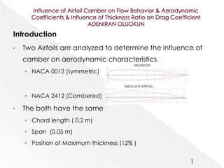
- 1. Introduction • Two Airfoils are analyzed to determine the influence of camber on aerodynamic characteristics. • NACA 0012 (symmetric) • NACA 2412 (Cambered) • The both have the same • Chord length ( 0.2 m) • Span (0.05 m) • Position of Maximum thickness (12% ) 1
- 3. • Boundary conditions • Constant free stream velocity U∞= 5 m/s. • At temperature 250C • 1 atm reference pressure • No heat transfer, no turbulence model • No slip at the airfoil walls • Domain boundaries of free slip • Outlet conditions of zero gauge average static pressure. 3 Computational domain
- 4. • Grid convergence • The result for the lift coefficient is plotted for 3 mesh sizes • 0.006 m mesh is chosen since it gives smoother result 4
- 5. Influence of airfoil camber on aerodynamic coefficients • Cambered airfoil produces greater lift & lift to drag ratio 5
- 6. • Influence of airfoil camber on Flow behavior • Total pressure For symmetric airfoil at 0, 8,12,& 15 degrees angle of attack 6
- 7. • Influence of airfoil camber on Flow behavior • Total pressure For cambered airfoil at 0, 8,12,& 15 degrees angle of attack 7
- 8. • Influence of varying the thickness ratio • As the thickness % is increased Drag coefficient increases • Influence of Varying Reynolds number on drag coefficient • As the speed is increased the drag coefficient reduces 8
- 9. • Boundary layer thickness and separation • Separation occurred at x=0.082 m then flow reattaches • A final separation occurs at x=0.18 m which is very close to the trailing edge • Conclusion • The camber of an airfoil is important for delay of boundary layer separation • The results gotten from the simulation at the same Reynolds number (65000) for the NACA0012 and NACA2412 shows the stall angles to be 11.60 and 14.80 respectively. • Separation will lead to lift as well as drag generation. • Lower Reynolds number generates more drag on an airfoil • The sharp peaks of the wall shear stress after separation are seen to be due to transition of boundary layers from laminar to turbulent 9 x (m) y (m) UT (m/s) du dy τw/µ (1/s) δ (m) 0.000702 0.000154 3.135554 1.28E-07 5.52E-06 0.023282 0.005513 0.007136 0.007698 4.12E-06 1.34E-10 2.90E-06 4.62E-05 0.002088 0.016758 0.010229 3.367934 1.50E-10 5.51E-06 2.72E-05 0.001884 0.031709 0.013356 5.675004 0.041262 5.56E-06 7424.083 0.001967 0.057865 0.015645 6.04E+00 0.030707 5.50E-06 5579.344 0.002349 0.080487 0.015614 -0.41172 -0.00854 5.50E-06 -1551.55 0 0.080487 0.015614 -4.12E-01 0.00582 5.50E-06 1058.182 0.004122 0.126845 0.011869 8.33E-01 2.83E-05 5.59E-06 5.059576 0.005534 0.148499 0.0091 1.35E-01 0.001567 5.58E-06 280.8696 0.000393 0.167461 0.006197 2.49E+00 0.000562 5.56E-06 101.144 0.005534 0.18278 0.003525 4.074433 -0.02198 5.57E-06 -3946.1 0.005551