1. ®
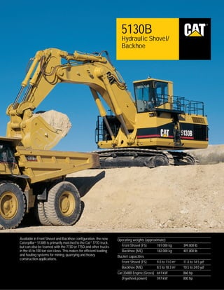
5130B
Hydraulic Shovel/
Backhoe
Available in Front Shovel and Backhoe configuration, the new
Caterpillar® 5130B is primarily matched to the Cat ® 777D truck,
but can also be teamed with the 773D or 775D and other trucks
in the 65 to 100 ton size class. This makes for efficient loading
and hauling systems for mining, quarrying and heavy
construction applications.
Operating weights (approximate)
Front Shovel (FS)
181 000 kg
Backhoe (ME)
182 000 kg
Bucket capacities
Front Shovel (FS)
9.0 to 11.0 m3
Backhoe (ME)
8.5 to 18.3 m3
Cat 3508B Engine (Gross) 641 kW
(Flywheel power)
597 kW
399,000 lb
401,000 lb
11.0 to 14.5 yd3
10.5 to 24.0 yd3
860 hp
800 hp
2. 5130B Hydraulic Shovel/Backhoe
Top performance and rugged durability combine to maximize your productivity.
Hydraulics
Powerful Cat hydraulics provide high
break-out and crowd force to maximize
bucket loads. The Cat Proportional
Priority Pressure Compensating (PPPC)
system allows smooth, efficient
operation. pg. 4 - 5
2
Power Train
The 5130B is powered by a single Cat
3508B engine with a high displacement
and conservative hp ratings for lower
maintenance and operating costs.
The 777D truck has field proven the
3508B engine design in the most
demanding mining applications. pg. 6
Structures
Extensive use of castings in high-stress
areas and box section design provide a
rugged, durable machine. Use of onepiece floating pins in main front structure
joints helps reduce wear and increase
strength. Thermal stress relief of front
structure components eliminates
residual stresses. pg. 7
3. Undercarriage
Cat designed, excavator-type
undercarriage is stable, durable and
maintenance free. pg. 8
Operator’s Station
Roomy, quiet cab has excellent
sightlines to the work area to help keep
operator fatigue low and production up
throughout the entire shift. pg. 9
Vital Information Management System
The latest in total machine monitoring,
(VIMS) monitors vital machine
functions. It helps reduce downtime
by keeping the operator informed of
current operating conditions and
allowing service personnel access to
logged data and machine faults. pg. 10
Buckets and Ground Engaging Tools
The 5130B’s agressive curved-floor
bucket design, efficient linkage
geometry and high crowd and breakout
forces provide superior bucket fill
factors. A wide selection of front shovel
buckets, backhoe buckets and ground
engaging tools allows precise machine
to application match. pg. 11
Modular Design
The eight modules that make up
the 5130B are easily shipped and
assembled. Components are located
with serviceability and maintenance
in mind. pg. 12
3
4. Hydraulics System
Caterpillar hydraulics deliver the power and control needed to keep material moving at high volume.
2 Engine
3 Pumps
4 Hydraulic tank
5 Hydraulic oil cooler
6 Fuel tank
7 Swing motors
8 Service platform
yy yyyyyy
yy
yy yyyyyy
yy
yy y yyy
yy
yyy
yy
yyy
yy
yyy
yy yyy
yyy
yy yyy
yyy
yy yyy
yyy
yy
yy
yy
1
yyyy
yy
yy
yy
yy
yy
yyy
yy
yyy
yyy
yyy
1 Engine radiator
2
3
7
4
yyy
yy
yyy
yyy
yyy
High breakout and crowd forces.
The 5130B Front Shovel and Backhoe
provide maximum forces at the bucket
cutting edge for improved material
penetration and bucket fill factors.
8
6
Four variable-displacement, piston
pumps act together to power the front
structure and travel systems. The swing
function is powered by its own variabledisplacement piston pump.
s
The front shovel has a breakout force
of 715 kN (161,000 lbs) and a crowd
force of 770 kN (173,000 lbs).
s
Main pumps are each rated at a
conservative 375 lpm (99 gpm) for
optimum service life.
s
The mass excavator arrangement
has a breakout force of 672 kN
(151,100 lbs) and a stick force of
624 kN (140,300 lbs), the highest in
its size class.
s
The swing pump is rated at 450 lpm
(119 gpm).
s
Other, smaller pumps power the
cooling fan drives, pump drive
cooler, pilot system, automatic track
tensioning system, and A/C system.
s
s
4
All pumps are serviced through
Cat dealers.
A bulkhead separates the engine and
pump compartments.
5
The modular design of the 5130B
provides unique advantages in hydraulic
system design and serviceability.
s
The longitudinal mounting of the
3508B engine and the low placement
of the hydraulic pumps eliminate the
need for a pressurized hydraulic tank.
s
Walk-around, lighted access to all
hydraulic system components allows
easy serviceability and quick daily
maintenance checks.
Hydraulic system filtration is provided
by 200 micron screens in the pump
discharge lines and 10 micron filters
in the return lines and case drain line.
5. Underspeed
Control
VIMS
PPPC
Valve
Swing
Valve
Swing
Pumps
ECM
Engine
Main
Pumps
Exclusive Caterpillar Proportional
Priority Pressure Compensating (PPPC)
valves are used in both the front
structure and travel systems.
s
s
Valve system only circulates fluid
when called for by the operator. There
is no unneeded fluid circulation. This
provides increased fuel efficiency and
reduced heat in the hydraulic system.
Automatic flow proportioning adjusts
pump output to the hydraulic circuits
based on the flow requirements of the
task at hand. When flow is required
by more than one function at a time
(such as boom up and stick out), the
valves determine the flow required
for each function and have pumps
supply that amount. This feature
allows smooth, precise, multifunction operation.
The swing circuit is controlled by an
open-center valve to assure quick, fullpowered response.
Hydraulic Tank
Electronically controlled pumps.
A Caterpillar designed microprocessor
regulates hydraulic pump output.
When hydraulic demand goes beyond
a prescribed threshold, the load sensing
control destrokes the pumps to prevent
excessive engine lugging.
s
Eliminates the need to maintain a
constant, costly, reserve of engine
power to prevent excessive engine
lugging.
s
Large-bore cylinders ensure efficient
load handling.
Cat’s XT hydraulic hose is exceptionally
strong and flexible. Reusable couplings
prolong hose assembly life.
S•O•S sampling valves are conveniently
located on the return rail on the right
side of the hydraulic tank.
Also allows hydraulic pumps to
use full engine power for precise
front structure or function response.
Hydraulic system cooling is provided
by a single, conventional core radiator
dedicated to the hydraulic circuit.
s
The variable-speed fan is temperature
controlled for greater fuel efficiency.
s
Extra-large cooling capacity allows
operation in ambient temperatures
of up to 50°C (122°F).
5
6. Cat 3508B Engine
The single engine of the 5130B provides an edge in operating costs and fuel efficiency.
The Caterpillar electronic control
system provides superior integration of
the engine and other machine systems.
All systems are designed specifically
for use in mining applications.
Automatic Engine Speed Control (AESC)
reduces fuel consumption and noise by
reducing the engine speed from 1750 to
1350 rpm if the hydraulic controls are
not actuated for four seconds.
Cold weather starting can be improved
with EUI’s cold weather starting mode.
This mode retards engine timing until
the engine is warmed to the correct
temperature.
The 3508B Electronic Unit Injection
(EUI) engine features:
s Excellent reliability with the latest in
protection programs.
Engine cooling system reduces fuel
consumption using a hydraulic driven
variable-speed fan. Fan operates at
a minimum speed of 400 rpm until
increased temperatures actuate a
solenoid and valve to increase fan
speed as needed.
High displacement, low rpm rating and
conservative hp ratings mean longer
service hours with less downtime for
maintenance and repair.
s
Protection during cold weather starts.
s
Excellent fuel efficiency.
s
Continuous monitoring of critical
engine functions.
s
Diagnostic data is accessible with a
single, electronic service tool.
s
Automatic altitude compensation
above 3050 m (10,000 ft).
s
Integrated ether injection.
s
Cold cylinder cutout.
6
Increased time between oil changes,
up 100 percent, from 250 hours to
500 hours between changes.
Two-piece piston design with aluminum
skirt and steel crown pivot at the wrist
pin provides added flexibility for
reduced piston scuffing.
S•O•S sampling valve located near oil
filter base speeds sampling.
7. Structures
The 5130B structural components are the backbone of the machines durability.
Heavy-duty castings are used
extensively in high-stress areas for
excellent, long-term structural
durability.
Castings are used in:
s Front end of the swing frame (which
is a single, massive casting)
s
Counterweight mounts
s
All boom and stick pin mounts
s
High digging forces are a result of the
efficient front linkage. Rod-ported
bucket tilt cylinders eliminate external
return lines, improving seal and rod life.
One piece floating pins are used at
swing frame to boom, boom to stick and
stick to bucket joints for extra strength
and life.
Front structure components are
thermally stress relieved to reduce
residual stresses from the welding
process, increasing structure life.
Carbody
s
Rugged box section construction
is used in key structures to provide
unsurpassed strength while eliminating
excess weight. Box section construction
is used in the booms, sticks, carbody
and roller frames.
Final drive mounts
7
8. Undercarriage
Durable, maintenance-free undercarriage absorbs stresses and provides excellent stability.
A wide track gauge offers the stability
needed for top production.
Automatic track tensioning maintains
the correct track tension.
The moving undercarriage is a
no-maintenance system that includes
some of the same features found on the
dependable D11-size track. Cat sealed
and greased track eliminates the need
for grease packing or shimming.
s
Track roller frames hold moving
undercarriage components rigidly in
place. They also absorbs stress loads
transmitted from the carbody.
s
Castings and high-strength steel
fabrication in crucial areas provide
superior structural strength.
s
Box beam section design includes
internal stiffening plates to provide
added strength.
s
Top plates are inclined to reduce
material build-up and packing under
carrier rollers.
s
Track motors and hydraulic lines are
fully guarded.
8
A gear pump supplies pressurized oil
to a cylinder, extending a push rod
which is attached to the idler.
Three shoe widths are available to
match your application.
Check valves hold the pressure in
the cylinder and maintain the correct
track tension when the engine is
not operating.
s
For periodic maintenance, there is a
manual release located on the track
roller frame.
s
Shock loads on the cylinders are
absorbed by an accumulator and
protected by a line relief valve.
Rock
s
General Purpose
s
s
s
Soft Underfoot
9. Operator’s Station
Designed for comfort and ease of operation.
Spacious operator compartment
measures 1790 mm (5'10") wide by
2178 mm (7'2") long by 2236 mm
(7'4") high and has an exceptional,
unobstructed view of the bucket and
loading area.
Air pressurization with positive filtered
ventilation keeps the cab environment
comfortable and clean.
s
Two fresh air filters remove dust and
particles before circulating.
Contour series seat is fully adjustable
for shift-long comfort.
s
Seat cushions reduce pressure on the
lower back and thighs.
s
Short armrests allow freedom of
movement with the joystick controls.
Joystick control consoles can be
repositioned independently according
to operator’s preference.
s
s
s
Cab offers ample leg room to the
front of the operator’s seat.
Trainee seat with seat belt at the rear
of the cab has cooler-size storage
under the seat cushion.
Cab and nearby components are
isolated to dampen sound and vibration.
s
Operator sound levels have been field
tested at or below 68 dB(A) with the
air conditioning on, doors closed and
the engine at rated speed.
s
Every side window has its own vent.
s
Front window has two large-diameter
vents to maintain excellent all-around
visibility, even in frost conditions.
s
s
Foot level vents and two largediameter vents in the console are
devoted to the operator.
KAB seat is available as an option.
s
Weight-compensated support.
s
Three-way seat cushion adjustment.
s
Backrest is adjustable from 56°
forward to 82° reclined.
Hydraulic controls are pilot operated
for low lever efforts and excellent
control.
9
10. Vital Information Management System (VIMS)
Provides operators, service technicians and managers with crucial operating data.
1
2
3
The VIMS system continuously displays
critical machine data. This information
can be used to keep the 5130B performing
at top production levels.
1. Upper screen display. On its upper
screen, the VIMS maintains a constant
display of four critical machine functions.
s
Engine coolant temperature.
s
Hydraulic oil temperature.
s
System air pressure.
s
Fuel level.
2. Lower screen display. The lower
screen displays operator-requested
information and also contains the
VIMS three-category alert system.
s
Display fields include both a numeric
reading in English or Metric units
(e.g. degrees of temperature) and an
electronic gauge which illustrates the
function’s current position relative to
a predetermined limit or setting.
10
3. VIMS keypad allows the operator
to access current machine system
information from twenty-by-two VIMS
display fields. The keypad is also used
by service personnel to access
diagnostic information.
The three-category alert system
provides advisory information to the
operator when conditions in a monitored
system exceed a prescribed setting for
ordinary operations.
s
The advisory category activates an
alert indicator lamp when a system
condition has been identified and
appropriate corrective action is
recommended.
s
In the operator advised category, an
action lamp flashes in addition to the
level one display.
s
Immediate shutdown advised, the
final category, sounds an audio action
alert in addition to the category two
action. The action lamp and alert
remain on until the system reading
returns to normal or the machine is
shutdown.
The VIMS diagnostics program
allows service personnel to download a
complete record of machine data events
and system diagnostics to a lap-top
computer.
s
This information can be used to
establish a baseline for machine
performance in specific applications
or to improve the effectiveness of
scheduled maintenance programs.
s
VIMS data makes it possible to
correct minor problems before they
cause extensive damage, which can
result in costly down time.
11. Buckets
Aggressive bucket design and efficient linkage configuration promote high bucket fill factors.
High fill factors for the 5130B Front
Shovel and Mass Excavator set this
machine apart from the competition.
Caterpillar’s quality design improves
breakout and crowd forces, increasing
fill factors.
s
Linkage geometry optimizes
mechanical advantage through the
loading cycle.
s
Curved floor bucket design moves
the bucket fulcrum away from the
cylinders, increasing breakout force;
promotes smooth material flow to the
back of the bucket.
Box-section construction is utilized
in the dozer portion of front shovel
buckets to provide torsional strength
when the bucket is closed for digging.
Steel castings are used in high-stress
areas such as the dozer hinges, bowl
pivots, cylinder mounts, and corner
adapters.
Hardened bearings improve the
durability of the pivot and cylinder
mounts in mass excavator buckets.
Heat-treated steel is used to improve
the service life of corner and center
adapters, cutting edges and side bars
which will be subjected to more
abrasive conditions.
Standard wear plates on the back,
sides and bottom reinforce front shovel
bucket structures. Wear packages with
Abrasion Resistant Material (ARM)
are also available for high abrasion
applications.
Bucket tips are top-pinned directly to
the adaptor for fast on-site replacement.
General purpose rock and penetration
tips are available to maximize
penetration and tip life.
Several front shovel and backhoe
buckets are available. Buckets range
from rock/high density buckets to coal
and light material buckets. Contact your
dealer for a precise match to your
application.
11
12. Modular Design
Provides a stable, productive machine that’s easy to transport and service.
Shipping and assembly. Machine
breaks down into eight modules for ease
of shipping.
s
Swing frame and carbody ship as a
single unit which means the swing
bearing doesn’t need to be assembled
or disassembled.
Maintenance and service access.
The right and left side modules provide
excellent service access as well as
storage and working space.
Right module includes walk-around,
lighted access to the engine, engine
cooling system, batteries, and hydraulic
pumps.
12
Left module includes cab riser which
allows stand-up access to hydraulic
pilot lines and to the main junction box
for electrical and electronic components.
It also includes a sheltered, lighted
service area for the hydraulic tank,
filters, hydraulic cooling system and
auto-lube reservoir.
Superior stability is achieved by
creating a lower center of gravity and
is a result of the modular design.
s
The left and right side modules are
positioned low in relation to the
swing frame module.
s
The longitudinal mounting of the
engine in the right side module makes
this stable, low positioning possible.
13. Engine
Caterpillar, four cycle, 3508B twin turbo-charged and aftercooled, diesel engine with electronic unit injection.
Ratings at 1750 rpm*
Gross power
Net power
kW
641
597
hp
860
800
*Power rating conditions
s
s
The following ratings apply at 1750 rpm
when tested under the specified standard
conditions for the specified standard:
Net power
Caterpillar
ISO 9249
SAE J1349
EEC 80/1269
DIN 70020
kW
hp
597
597
591
597
800
800
792
800
829
s
s
Features
based on standard air conditions of
25°C (77°F) and 99 kPa (29.32 in Hg)
dry barometer
used 35° API gravity fuel having an
LHV of 42 780 kJ/kg (18,390 Btu/lb)
when used at 30°C (86°F)
net power advertised is the power
available at the flywheel when the
engine is equipped with fan, air
cleaner, muffler, and alternator
no derating required up to 3050 m
(10,000 ft)
s
s
s
s
s
s
Dimensions
Bore
Stroke
Displacement
Cat electronic control system monitors
operator and sensor inputs to precisely
optimize engine performance, at that
altitude, with electronic unit injectors
two hard-faced inlet and exhaust
valves per cylinder, valve rotators and
hard alloy-steel seats
self-aligning roller followers on
camshaft
two-piece pistons with steel crown
(three rings) and thermally isolated
aluminum skirt
direct-electric, 24-volt starting system
with 100-amp alternator and four
210-amp-hour, low-maintenance,
high-output, 12-volt batteries
deep bowl combustion chamber
170 mm
6.7 in
190 mm
7.5 in
34.5 liters 2105 cu in
Hydraulic System
The hydraulic system for front structure and travel functions is supplied by four, variable displacement pumps. A separate
variable displacement pump provides for the swing function.
Main system, piston-type pumps, closed center
Output at 1915 rpm
Features
375 liters/min (x 4)
99 gpm (x 4)
35 000 kPa
31 000 kPa
5000 psi
4500 psi
s
Relief valve setting
Travel
Front structure
s
s
Swing system, piston-type pump, open center
Output at 1915 rpm
450 liters/min
117 gpm
35 000 kPa
25 000 kPa
5000 psi
3620 psi
56 liters/min
14.5 gpm
4000 kPa
7000 kPa
580 psi
1000 psi
Relief valve setting
Accelerating
Decelerating
s
Pilot system, gear-type pump, open center
Output at 1915 rpm
main hydraulic pumps are
electronically controlled and
dependent on engine speed
engine automatically idles down with
inactive controls and resets to original
speed upon control engagement
work cycle performance is optimized
during single-function, high front
structure speed requirements by
combining pump flows
all valves are pilot operated for ease
of operation and excellent control
all lines include primary and
secondary relief valves as well as
anti-cavitation valves
s
Relief valve setting
Controls
Track Tension
5130B Hydraulic Shovel/Backhoe specifications
13
14. Swing Mechanism
Drive
Hydrostatic with independent planetary
reduction.
Drive system is fully hydrostatic.
Brakes
Ratings
Ratings
587 kN.m
(433,240 lb.ft)
Time for 90° lift and swing
7.3 sec
(loaded bucket)
Swing Torque
Service brake features
Maximum
Drawbar Pull
Maximum
Travel Speed
s
872 kN
(196,000 lbs)
s
3.3 kph
(2.1 mph)
s
s
Features
s
Features
s
s
power for the swing mechanism
originates with two hydrostatic motors
with independent planetary reduction
and integral multiple disc brakes
internal gearing is totally enclosed,
and is continuously lubricated
together with the pinion
s
each track is driven by an independent,
bent-axis piston motor via integral
planetary final drives
multiple disc brakes are spring
engaged, pressure released; each
drive module is well integrated into
the roller frame for total protection
two wet, multiple-disc brakes are used
on the final drive input shafts
spring-applied, hydraulically released
actuating a travel control simultaneously
releases the brakes
when the controls are released, the
brakes automatically apply
Parking brake features
s
s
wet, multiple disc brakes
spring applied, hydraulically released
Track
Steering
Purpose built excavator undercarriage with cast, extreme service shoes.
Two rocker pedals with detachable hand
levers control steering and travel
functions.
Choice of
s
s
s
650 mm (26") shoes/Rock
800 mm (32") shoes/General Purpose
1000 mm (39") shoes/Soft Underfoot
Controls
s
Ground Pressures
Front Shovel
with 650 mm (26") shoes
with 800 mm (32") shoes
with 1000 mm (39") shoes
Mass Excavator
with 650 mm (26") shoes
with 800 mm (32") shoes
with 1000 mm (39") shoes
s
216 kPa
178 kPa
144 kPa
31.4 lb/in2
25.8 lb/in2
20.9 lb/in2
218 kPa
179 kPa
145 kPa
31.6 lb/in
26.0 lb/in2
21.0 lb/in2
s
s
2
s
Features (per side)
s
s
s
s
48 track shoes
8 track rollers
2 carrier rollers
2 track guiding guards
14
5130B Hydraulic Shovel/Backhoe specifications
s
controls are pilot-operated for reduced
efforts
left pedal and lever control left track;
right pedal and lever control right track
when idlers are in front, pushing both
pedals or levers forward moves the
excavator straight ahead
rocking both pedals or pulling both
levers backward moves the excavator
straight back
moving one pedal or lever more than
the other, either forward or backward,
results in a gradual turn
moving one pedal or lever forward
and the other pedal or lever backward
counter-rotates the tracks for spot turns
15. Front Structure Controls
Service Refill Capacities
Two joystick hand levers actuate boom, stick, bucket and swing (SAE pattern).
Boom/Bucket Controls (Right Joystick)
s
s
s
move forward and backward to lower
and raise boom
move left and right to control bucket
curl and dump
button on top is boom float control
(Front Shovel only)
Other Features
s
s
oblique movement of either lever
operates two functions simultaneously
manually applied lever on left console
cuts off pilot pressure for joysticks
and travel controls and electrical
power for engine starting circuit
Stick/Swing Controls (Left Joystick)
s
s
s
move forward and backward to move
stick out and in
move left and right to control
direction of swing
button on top controls horn
L
Fuel Tank
Cooling System
Engine Oil
Pump Drive
Swing Drive
Final Drive (each)
Hydraulic System
(including tank)
Hydraulic Tank
Gallons
2600
300
125
73
14
31
687
79
33
19
3.7
8.2
1800
1225
476
324
Cab
Caterpillar cab with integral Falling Object Guard is standard in North America,
Europe and Japan.
Cab Certifications
s
The cab structure is designed to protect
the operator from falling objects, and
is certified under SAE J1356 FEB88
and ISO 3449-1984 specifications.
A guard is available for the front
windshield and is also certified under
SAE J1356 FEB88. Currently there is
no ISO specification for front guard
structures.
Note
When properly installed and maintained,
the cab offered by Caterpillar, when
tested with doors and windows closed
according to ANSI/SAE J1166 MAY90,
meets OSHA and MSHA requirements
for operator sound exposure limits in
effect at time of manufacture. The
operator sound pressure level is
68 dB(A) when measured per ISO 6394
or 86/662/EEC.
5130B Hydraulic Shovel/Backhoe specifications
15
16. Dimensions
All dimensions are approximate.
5250 mm
17'3"
Swing Radius
6620 mm
21'9"
5140 mm
15'11"
5000 mm
19'4"
5680 mm
18'8"
6550 mm
21'5"
2350 mm
7'9"
4395 mm
14'5"
1800 mm
6'3"
960 mm
3'2"
2045 mm
6'9"
5562 mm
18'3"
4720 mm
15'6"
7270 mm
23'10"
5370 mm
17'7"
8775 mm
28'9"
* Dimension shown with 650 mm (26 in) shoes
Supplemental Specifications
Shipping Dimensions*
Truck
Module
Weight
Length
Width
Height
kg
1
2/3
4
5
6
7
8
Carbody/Swing Frame
Track Roller Frame (x2)
650 mm (26") shoes
800 mm (32") shoes
1000 mm (39") shoes
Left Hand Enclosure
Cyl. Skid (x4)
Cyl. Skid (x2)
Cyl. Skid (x2)
Cab
Right Hand Enclosure
Stick
Parts Box/Ladder
Parts Box
Handrail Skid
Boom
Parts Box/Ladder
Handrail Skid
Boom
Counterweight
Bucket
Bucket
Stick
Bracket Skid
FS
ME
ME
ME
FS
FS
FS
ME
FS
ME
ME
ME
mm
in.
mm
in.
mm
in.
38 630
FS
ME
ME
lb
85,160
7061
278
4115
162
3962
156
23 610
24 640
25 770
8050
1800
2800
2000
1810
13 810
6170
1910
1930
930
15 260
2940
930
20 530
20 970
15 340
8560
6220
1370
52,060
54,320
56,820
17,740
3960
6170
4410
3990
30,440
13,610
4210
4260
2040
33,640
6470
2040
45,260
46,220
33,820
18,870
13,710
3020
7137
7137
7137
5766
3835
3835
3835
2337
5664
4928
2235
2235
3988
6401
2235
3988
8560
5944
3683
3302
5258
1524
281
281
281
227
151
151
151
92
223
194
88
88
157
252
88
157
337
234
145
130
207
60
1499
1499
1499
2337
914
914
914
2007
2438
1524
1092
1092
2286
2032
1092
2286
1981
991
2743
2718
1016
1448
59
59
59
92
36
36
36
79
96
60
43
43
90
80
43
90
78
39
108
107
40
57
1905
1905
1905
2616
610
686
686
2997
3048
1778
1194
991
1118
2108
1194
1118
3404
2510
2743
2718
2286
787
75
75
75
103
24
27
27
118
120
70
47
39
44
83
47
44
134
99
108
107
90
31
* Items that are not marked with an FS or an ME apply to both machines.
16
5130B Hydraulic Shovel/Backhoe specifications
17. Standard Equipment
Optional Equipment
Standard and optional equipment may vary. Consult your Caterpillar dealer for
specifics.
Optional equipment may vary. Consult
your Caterpillar dealer for specifics.
Action Alarm
Air conditioner/heater/defroster system
Air cleaner, dry type, with precleaner
Alarm, travel
Alternator, 105 amp
Automatic engine speed control
Automatic, air powered, Lincoln 64 l
(17 gallon) capacity, lubrication
system
Cab, resiliently mounted, sound
suppressed and pressurized
(see operators station for features)
Cat Underspeed Control
Backhoe Arrangement
Buckets (see below)
Cold weather starting options
Engine prelube
Front Shovel Arrangement
Ground Engaging Tools
General purpose tips
Penetration tips
Edge protection
Sidebar protectors
Seat, KAB, operator
Track shoes:
650 mm/26" rock shoes
800 mm/32" general purpose shoes
1000 mm/39" soft underfoot
Windshield guard, front
Wiggins central service center
Engine, Cat 3508B EUI Diesel
Engine oil quick change system
Lights, Halogen, working
Fuel tank — fast refill system
Locks, door and cap — one key system
Lube reel, manual (ME only)
Lube barrel, refillable
Mirrors, rearview, left on cab
Seat belt, retractable
Vital Information Management System
(VIMS)
Buckets
5130B Front Shovel — Bucket Specifications
Capacity
Weight
Width
Teeth
m3
Rock
Rock w/ARM
High Density
yd3
kg
lb
mm
in.
11.0
11.0
9.0
14.5
14.5
12.0
17 900
18 900
17 700
39,500
41,650
39,000
3600
3600
3050
142
142
120
6
6
5
Mat’l Weight
t/m3
lb/yd3
1.7
1.7
2,900
2,900
3550
5130B Mass Excavator Buckets — Bucket Specifications
Capacity
Weight
Width
Teeth
m3
High Density
Excavation
Rock
Coal
Coal
yd3
kg
lb
mm
in.
8.5
10.5
10.5
13.6
18.3
11.0
13.7
13.7
17.8
24.0
7820
8560
9750
8750
9200
17,250
18,870
21,500
19,300
20,300
2810
2810
2810
3505
3680
111
111
111
138
145
5
6
5
9
9
Mat’l Weight
t/m3
lb/yd3
2.2
1.7
1.7
1.1
0.9
3,700
2,900
2,900
1,900
1,500
Note
Other bucket options are available. Contact your dealer for additional bucket selections.
5130B Hydraulic Shovel/Backhoe specifications
17
18. Front Shovel Working Ranges
Front Shovel (F.S.) configuration
ft
m
14
44 13
40 12
36 11
32
10
9
28
8
24
7
20
6
16
5
12
777D
4
3
8
2
4
1
0
0
4
1
8
2
3
12
4
13
44
12
40
11
36
10
32
9
8
28
7
6
5
24
20
16
4
3
12
2
8
1
4
Max. Reach...................................... 12.4 m (40.7')
Max. Level Crowd Distance ..........
4.3 m (14.1')
Max. Loading Height .....................
9.1 m (29.8')
Max. Loading Height
at 8 m (26') Reach..........................
8.3 m (27.2')
Breakout: Force .............................. 715 kN (161,000 lb)
Crowd: Force ..................................770 kN (173,000 lb)
18
5130B Hydraulic Shovel/Backhoe specifications
0 m
0 ft
19. Backhoe Working Ranges
Mass Excavation (M.E.) configuration
ft
m
52
16
15
48
14
44 13
40 12
36 11
32
10
9
28
8
24
7
20
6
16
5
12
4
3
8
2
4
1
0
0
4
1
777D
8
4m
2
3
12
4
16
5
20
6
24
7
28
3.8 m (12'6") Stick
5.2 m (17'0") Stick
8
9
29
16
52
15
14
48
13
44
12
40
11
10
36
32
9
8
28
7
6
5
4
24
20
16
3
12
2
8
1
4
3.8 m (12'6") Stick
0 ft
5.2 m (17'0") Stick
Max. Reach......................................
14.9 m (48.9')
Max. Digging Depth .......................
8.4 m (27.6')
Max. Loading Height .....................
9.1 m (29.8')
Breakout: Force .............................. 672 kN (151,100 lb)
Crowd: Force .................................. 624 kN (140,300 lb)
0 m
16.2 m (53.1')
9.7 m (31.8')
9.6 m (31.5')
672 kN (151,100 lb)
537 kN (120,700 lb)
5130B Hydraulic Shovel/Backhoe specifications
19