1. WILLIAM ALLEN MAIN
(858)692-7752
Will_Main@outlook.com
Senior Design
ENSC 28 - Hydraulic Track Drive
Project Description:
FLSmidth Spokane designs and manufactures large material handling equipment for
customers around the globe. One of the product lines sold by FLS is the mobile stacking
conveyor systems (MSC). These MSCs are propelled across the mine site using a track
system. This project will design a hydraulic cylinder drive mechanism to replace the
motor/gearbox/sprocket drive in the current design.
Deliverables:
1. Project plan, detailed deliverables, and schedule as derived from the Scope of Work
provided by FLS.
2. Literature research into similar mechanisms.
3. Detailed mechanical design of a D4 track system using hydraulic cylinders to replace the
motor/gearbox/sprocket drive.
4. Finite Element Analysis of all load bearing components.
5. Detailed mechanical design of a scaled model track system.
6. Test plan of the track system.
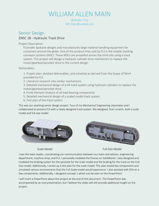
This was our yearlong senior design project. Four of my Mechanical Engineering classmates and I
collaborated to present FLS with a newly designed track system. We designed, from scratch, both a scale
model and full-size model.
Scale Model Full-Size Model
I was the team leader, coordinating our communication between our team and advisor, engineering
department, machine shop, and FLS. I personally modeled the frames on SolidWorks. I also designed and
modeled the braking system for the sprocket for the scale model and the braking for the track on the Full-
Size model. Additionally, I wrote up a test plan for the scale model. This plan tested key components and
simulated various environments that the Full-Scale model would experience. I also assisted with FEA on a
few components. Additionally, I designed concept 1 which can be seen on the PowerPoint.
I will insert a PowerPoint about this project at the end of this document. This PowerPoint was
accompanied by an oral presentation, but I believe the slides will still provide additional insight on the
project.
2. Junior Design
Pawn Tray Loader Project
Goal: Design device to sort 2 different colored pawn pieces into a tray in any specified order
using sheet metal, 3D printed parts and pneumatic cylinders.
Requirements:
- Limited to 4 pneumatic cylinders,
- Use provided trays and pawn pieces
- Use only sheet metal, 3D printed parts, and fasteners
- Computer program needs to be able to sort pawns in any specified order
- Footprint constraint
I personally designed the main loader portion of the project. This was a 3D printed part designed on
SolidWorks. There was an incentive to have a lower number of total parts, so I designed it as one solid
piece taking into thought the alignment on the 3D printer.
I have provided a link of a video of our machine in operation. This video shows our Pawn Tray Loader
loading the trays in a checkered pattern. The main difficulties with this project were the light weight
pawns constantly tipping over and the depth of the wooden trays. The video shows that we were able to
overcome these obstacles as our machine flawlessly loads the trays.
https://www.youtube.com/watch?v=83OVvw_7i5M
3. Junior Design
Chip Flipper
Goal: Design device out of cardboard which takes a stack of two different colored poker chips,
flips each chip once, and finishes with a single stack of alternating colored chips. Materials
available: cardboard, hot glue gun, paperclips. Speed and accuracy are key
This was just a small initial project to introduce us into the engineering project system as well as have us
improve our teamwork. Even though it was a minor project, I really did enjoy it. For this project, we
worked in a group of four. We each designed a prototype chip flipper. My particular design was chosen
for construction. My design considered both speed and accuracy.
This designed considered speed by picking one
chip up and dropping the other chip at the same
time. I do not have a video available so I will
describe the operation.
In the “slider” piece, which you push and pull to
operate, there are two square slots. In photo 2, you can see two holders. This is where two different
colored chips are placed. On the right holder in photo 2, you can slightly see that there is a slot on the
slider. The other slot is in the middle where the chips are dropped and flipped. The slider is then pulled to
the position seen in photo 3. It is now dropping off the chip from the right holder and picking up the chip
from the left holder. The three layer cardboard design where the slider is located led our device to be
accurate. The space is the near exact thickness of one poker chip to only allow one chip in the slot at a
time. After the chips were flipped as they fell through the middle section, the device is picked up and the
chips are sitting in a stack, alternated and flipped.
During the testing with the various devices made by other teams, ours was voted to be the most accurate
and quickest. Our accuracy was one hundred percent. Not one group was able to make our device fail
while following our instructions. This project was a great beginning to many more engineering projects.
1
2
Slider
3
6. DELIVERABLES
1. Three additional track drive concepts w/ matrix
evaluation
2. 3D models of scale and full-size design
3. 2D fabrication drawings of scale and full-size model
4. Finite Element Analysis of key components
5. Specification document for clutch requirements
6. Full-size model calculations report
7. Test plan for scale model
7. TARGET DESIGN SPECIFICATIONS
• INTEGRATE INTO A D4 SIZE TRACK SYSTEM
• UTILIZE HYDRAULIC CYLINDERS FOR PROPULSION
• AVAILABLE HYDRAULIC POWER OF 3000 PSI, WITH AN OPTION OF
5000 PSI
• REDUCE REPAIR TIME AND COST BY USING READILY-AVAILABLE, OFF-
THE-SHELF COMPONENTS
• CAPABLE OF MOVING MOBILE STACKING CONVEYERS 1 METER/MIN IN
EITHER A CONTINUOUS OR STOP-AND-GO MOTION
• UP TO 12 TRACK SYSTEMS WILL WORK TOGETHER SPACED 50 FEET
APART
• SUPPORT LOADS CAPABLE OF CREATING UP TO 206 KPA (30 PSI)
GROUND BEARING PRESSURE
13. SCALE MODEL DESIGN
• Rubber track (Caterpillar 300.9D)
• Steel inner and outer frame (A36 or A572)
• Numerous off-the-shelf components
– Sprockets, rollers, hydraulic cylinders,
14. SCALE MODEL BUDGET
• Preliminary budget estimate: $5400
• Final budget estimate: $4686.36
15. SCALE MODEL TEST PLAN
Test Type Requirements Environment
VIBRATION MIL-STD 810-514.6 Laboratory Shaker- varying frequency
and intensity
INCLINE/DECLINE Slope of 20% Grade Outdoor - Muddy, rocky and dirt
surfaces.
RUGGED/MUDDY Travel 1 meter/min
for 15 min
Outdoor – Muddy (Track should sink up
to 3 inches in mud)
SKID STEERING Performance
unaffected by winch
While track is operating - Winch is
attached to one end of track pulling at 1
meter/min
FAILURE/SAFETY Refer to FMEA