Dell H2C™ Technology: Hybrid Cooling for Overclocked CPUs
•
1 gefällt mir•958 views

This technical 2007 paper describes Dell's hybrid H2Ceramic (H2C) cooling system, which is used in high-end Dell XPS gaming systems.

Empfohlen
Empfohlen
Weitere ähnliche Inhalte
Andere mochten auch
Andere mochten auch (9)
Ähnlich wie Dell H2C™ Technology: Hybrid Cooling for Overclocked CPUs
Ähnlich wie Dell H2C™ Technology: Hybrid Cooling for Overclocked CPUs (20)
Mehr von Wayne Caswell
Mehr von Wayne Caswell (20)
Kürzlich hochgeladen
Kürzlich hochgeladen (20)
Dell H2C™ Technology: Hybrid Cooling for Overclocked CPUs
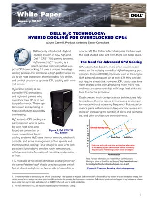
- 1. January 2007 White Paper t TM January 2007 DELL H2C TECHNOLOGY: HYBRID COOLING FOR OVERCLOCKED CPUS Wayne Caswell, Product Marketing Senior Consultant Dell recently introduced a hybrid spacecraft. The Peltier effect dissipates the heat over cooling system in new high-end the cold shaded side, and from there into deep space. Dell™ XPS™ 710 gaming systems. H2Ceramic (H2C™) cooling is a The Need for Advanced CPU Cooling patent-pending technology that sup- CPU cooling has become more of an issue in recent ports CPU overclocking.1 It uses a unique two-stage years, as the industry moved to higher-frequency pro- cooling process that combines a high-performance liq- cessors. The Intel® 8088 processor used in the original uid-to-air heat exchanger, thermoelectric fluid chiller, IBM personal computer ran at only 4.77 MHz and did and control circuitry to optimize CPU cooling with mini- not require a heat sink. However, CPU clock rates have mal power. risen sharply since then, producing much more heat, H2Ceramic cooling is de- and most systems now ship with large heat sinks and signed for PC enthusiasts fans to cool the processor. and high-end gamers who Dual-core and multi-core processor architectures help overclock their CPUs to get to moderate thermal issues by increasing system per- top performance. These sys- formance without increasing frequency. Future perfor- tems need extra cooling to mance gains will rely less on frequency increases and help avoid failures caused by more on increasing the number of cores and cache siz- overheating. es, and other architecture enhancements. H2C extends CPU cooling ca- pacity beyond what is possi- ble with heat sinks and forced-air convection or Figure 1. Dell XPS 710 H2C Edition more conventional liquid cooling systems. H2C uses thermal sensors, electronic controls, and active management of fan speeds and thermoelectric cooling (TEC) voltage to keep CPU tem- perature slightly above ambient room temperature, which prevents the formation of humidity condensation or frost. Note: For more information, see “Intel® Multi-Core Processors: TEC modules at the center of the heat exchanger rely on Making the Move to Quad-Core and Beyond,” http://www.intel.com/ the same Peltier effect2 that is used to counter the ef- technology/architecture/downloads/quad-core-06.pdf fect of direct sunlight on only one side of a satellite or Figure 2. Thermal Density Limits Frequency 1. For more information on overclocking, see “What Is Overclocking?” in the appendix of this paper. Dell warrants the full functionality of your system at factory overclocked settings. Over- clocking beyond factory settings may cause system instability and reduce the operating life of your system components. Dell does not provide technical support for any hardware or software issues arising from any third party application, such as NVIDIA® nTune 5.0, used to enable overclocking. 2. For more information on TEC, see http://en.wikipedia.org/wiki/Thermoelectric_Cooling. 1
- 2. www.dell.com/innovation Dell™ H2C™ Technology: Hybrid Cooling for Overclocked CPUs Despite these improvements, more advanced cooling is quad-core processor, H2C was found to be up to 6° C often required when a CPU is overclocked in a high-end cooler than the XPS 710 air cooling solution at 2.66 GHz, gaming system. CPU heat output tends to rise exponen- up to 5° C cooler when overclocked to 2.93 GHz, and up tially during overclocking. Liquid-cooling solutions exist, to 9° C cooler when overclocked to 3.2 GHz. This perfor- but overclocking can require the additional cooling pro- mance is achieved with a lower fan speed than that vided by the H2C technology. achieved when cooling with the standard heat sink.3 As implemented in the XPS 710, H2C does not address The XPS 710 H2C Edition is designed for years of main- the cooling requirements of advanced graphics acceler- tenance-free operation, where system cooling increas- ators, which continue to drive improved performance es automatically during peak loads. For user through faster clock rates and higher wattage. Still, H2C convenience, the system ships with overclocking en- helps improve overall thermal capacity by efficiently re- abled as the factory default. Users can adjust overclock- moving CPU heat from the cabinet. This allows fans on ing, H2C cooling, and other system settings through the graphics cards to cool more efficiently, extending system BIOS. the system’s operation at maximum performance. Thermoelectric Cooling (TEC) and Peltier Effect Cooling Alternatives A key component of the H2C technology is the TEC heat Figure 3 shows various cooling technologies, with nat- exchanger. At the heart of this heat exchanger are two ural convection cooling through a simple heat sink at thermoelectric modules that use the Peltier effect to the top of the list, and liquid nitrogen at the bottom. The pump heat from one ceramic face to the other ceramic target cooling level for H2C is just above ambient room face when a DC current is applied. Conceptually, it is temperature because colder temperatures can cause similar to a refrigerator that uses a refrigerant to move condensation or frost that damage the system. Be- heat out into the environment, but the TEC uses elec- cause thermoelectric cooling can cool below ambient trons instead of refrigerant. room temperature, H2C includes sensors and control Heat Rejected logic to keep recirculating fluid temperature from falling below the ambient temperature. 60°+ C (140°+ F) Natural convection (heat sink) p-Type Semiconductor Positive (+) n-Type Semiconductor Electrical Conductor (Copper) Forced air convection (fan + heat sink) Electrical Insulator (Ceramic) Liquid cooling (water) Negative (-) ~23° C (73° F) Ambient air temperature Thermoelectric cooling (TEC) Heat Absorbed Phase-change cooling (refrigeration) Figure 4. Thermoelectric Module -190° C (-310° F) Cryogenics (liquid nitrogen) When the current is applied, one side of the TEC mod- ule (or heat pump) is cold, and the other is hot. Revers- Figure 3. Typical Full-Load Temperatures ing the polarity causes heat to flow in the opposite direction. Varying the current allows for tight tempera- H2C Cooling Benefits ture controls. For more detail on thermoelectric cooling, see www.melcor.com/pdf/Thermoelectric%20Handbook.pdf. H2C technology helps to extend CPU life and reduce overclocking risks from heat build-up. In Dell perfor- Figure 5 shows the location of the TEC modules and in- mance tests using an Intel Core™ 2 Extreme QX6700 ternal fin structure. Thermal grease is used on both 3. Based on testing using a standard maximum-power utility benchmark by Dell performance labs in October 2006 on a pre-production XPS 710 with processor as specified. The system was also equipped with 256 megabytes of dual-channel DDR2 533-MHz 4x memory, dual NVIDIA 7950 GX2 graphics card, and 4x 40-gigabyte hard-disk drive formatted with Raid 0. Actual performance will vary based on configuration, usage, and manufacturing variability. 2
- 3. January 2007 Heat dissipated by the CPU is transferred to a CPU cold 1 plate that is attached with thermal grease and approxi- mately 45 pounds of force. The cold plate has a very fine fin structure inside to enhance heat transfer to the fluid. A high reliability pump circulates fluid through the system, drawing in heat from the cold plate. The pump includes a reservoir and vol- ume compensator that can hold up to 20 cc of fluid to compen- sate for permeation loss over life. An integrated tachometer provides feedback to the system controller about the pump's Figure 5. Cut-Away View of Heat Exchanger speed. sides of the TEC devices to reduce thermal resistance, and coil springs maintain compressive force between the TEC devices and heat sinks. Hoses are attached to the fluid heat exchanger with hose barb fittings. Fluid passing through the heat exchanger is cooled by the TEC Peltier effect and exits at nearly ambient air tem- perature. H2C Thermal Flow Detail Figure 6 shows the components of the H2C technology. Cool air is pulled through an efficient fluid-to-air heat 2 exchanger that works much like a car's radiator to re- move most of the heat in this first stage of cooling. The heat exchanger is custom-designed and built by Delphi for Dell. Figure 6. HPC Components What happens to the heat as it moves from the CPU and exits at the back of the system into the room? To under- stand this process, it is helpful to look at the fluid flow through the H2C components shown in the following series of illustrations. 3
- 4. www.dell.com/innovation Dell™ H2C™ Technology: Hybrid Cooling for Overclocked CPUs H2C Testing The 120-mm-diameter fan used in the H2C system is also 3 used in many other Dell systems in conjunction with more When looking for a cooling system for PC enthusiasts, common heat sinks. Enclosed in a shroud to amplify the Dell evaluated the leading liquid-cooling solutions be- wind tunnel effect, it pulls ambient room air into the front fore choosing to develop a custom two-stage liquid/ of the systems unit and through the fluid-to-air heat exchanger before pushing it through additional heat sinks on the TEC fluid TEC solution for better performance. In testing against chiller and out the back. Fan speed is controlled by a pulse width the best custom solutions available, H2C was proven to modulation signal from the controller. be cooler in overclocked mode and potentially quieter in normal operating mode as shown in Figure 7. The second stage of the cooling process is performed by 4 a Dell custom-designed thermoelectric fluid chiller, which uses an internal fin structure to transfer heat to a TEC de- vice. For this component, Dell went to CoolIT Systems, a compa- ny with experience manufacturing similar fluid chillers for PC cooling applications. Figure 7. Fan Speed vs. CPU Case-to-Ambient Resistance In Figure 7, the vertical reference lines show how H2C can keep CPU temperature lower than alternative cool- ing systems at any given fan speed. Horizontal lines suggest that H2C needs lower fan speeds to achieve the same amount of cooling. The combination of system-level firmware and controller Conclusion 5 circuitry manages the delivery of power to the TEC devic- In addition to the advanced cooling offered in the H2C es and regulates the speed of the fan and pump. This combina- Edition of the XPS 710 systems, all Dell Dimension™ tion cools the CPU as much as possible during normal and over- clocked operation. and XPS systems feature the QuietCase™ design and Balanced Technology eXtended (BTX) form factor that have been recognized for cool and quiet operation. For more information on H2C and Dell gaming systems, see www.dell.com/h2c. 4
- 5. January 2007 APPENDIX: WHAT IS OVERCLOCKING? Overclocking is the process of forcing a computer com- powerful fans is usually required. Liquid cooling is ponent to run faster than designed or designated by the often used as well and, when properly implement- component manufacturer. The PC enthusiasts who ed, provides much more effective cooling than heat choose to overclock their components usually focus sink and fan combinations. Dell's H2C cooling tech- their efforts on processors, graphics cards, mother- nology goes even further to keep overclocked CPUs board chip sets, and memory, but expansion buses can cool under pressure. H2C is smarter and more ef- also be overclocked. fective than other Dell-tested liquid cooling sys- tems. Overclocking allows one to boost a computer system's 2. Stability and functionality—An overclocked compo- performance by increasing clock frequencies. There are nent is by definition operating outside of the manu- several methods of overclocking, and no two compo- facturer's recommended operating conditions, nents will overclock by exactly the same amount. which may lead to system instability. An unstable Considerations before Overclocking overclocked system, while fast, can be frustrating to use. Testing the system is required to determine 1. Cooling—Due to the excessive heat produced by whether or not it is stable. overclocked components, an effective cooling sys- 3. Measuring effects of overclocking—Measuring the tem is critical to avoid damaging the hardware. Be- actual improvement from overclocking may be cause most stock cooling systems are designed for problematic. Even if statistics for the clocks demon- the amount of heat produced during non-over- strate an increase, the actual perceptible improve- clocked use, a more effective cooling solution, of- ments may not be visible. ten employing heavy-duty heat sinks and more Dell warrants the full functionality of your system at factory overclocked settings. Overclocking beyond factory settings may cause system instability and reduce the operating life of your system components. Dell does not provide technical support for any hardware or software issues arising from any third party application, such as NVIDIA nTune 5.0, used to enable overclocking. THIS WHITE PAPER IS FOR INFORMATIONAL PURPOSES ONLY, AND MAY CONTAIN TYPOGRAPHICAL ERRORS AND TECHNICAL INACCURACIES. THE CONTENT IS PROVIDED AS IS, WITHOUT EXPRESS OR IMPLIED WARRANTIES OF ANY KIND. © 2007 Dell Inc. All rights reserved. Trademarks used in this text: Dell, the DELL logo, Dell Dimension, XPS, QuietCase, and H2C are trademarks of Dell Inc.; Intel is a registered trademark and Core is a trademark of Intel Corporation; NVIDIA is a registered trademark of NVIDIA Corporation in the United States and/or other countries. Other trademarks and trade names may be used in this document to refer to either the entities claiming the marks and names or their products. Dell Inc. dis- claims any proprietary interest in trademarks and trade names other than its own. 5