SlideShare ist ein Scribd-Unternehmen logo
1 von 16
Downloaden Sie, um offline zu lesen
Medium Voltage HRC FUSES 
Catalogue sheet B30/06.03e
1. FEATURES 
− High rupturing capacity 
− Short−circuit current limiting 
− Low rated minimum breaking current (Imin) 
− Low switching overvoltages (Um) 
− Can be used with switch disconnector (it is fitted with 
a medium−size striker pin) 
− Dimensions acc. to DIN and IEC Standards. 
2. APPLICATIONS 
The HRC (high rupturing capacity) fuse−links are used 
to protect transformers, capacitor banks, cable and 
overhead lines against short−circuits. They protect 
switchgears from thermal and electromagnetic effects of 
heavy short−circuit currents by limiting the peak current 
values (cut−off characteristic) and interrupting the currents 
in several milliseconds. 
The type BWMW fuse−links interrupt overload 
currents greater than Imin (for the Imin values refer to Table 1). 
In situations where overloads lower than Imin are to be 
interrupted by the protective system, a switch− 
disconnector fitted with an overcurrent protecting device 
is to be used together with the type BWMW fuse−links. 
BWMW fuse−links can be used with type BWMP, 
BWMPE, BWMPNS, BWMPNW and BPS−01 fuse−bases 
as well as type OR5 or NALF switch−disconnectors. 
3. ENVIRONMENTAL OPERATING 
CONDITIONS 
BWMW fuse−links can be operated under the following 
environmental conditions: 
− on indoor and outdoor equipment, 
− at ambient temperatures of −30oC to +40oC, 
− at relative humidity of ambient air of 100% at 
a temperature of +20oC. 
4. DESIGNATIONS VERSIONS 
4.1 BWMW−fuse−links numbering system 
The numbering system for the BWMW fuse−links has 
four alphanumerical sections as shown in the diagram 
below. 
4.2 BWMP−fuse−base numbering system 
The numbering system for the BWMP fuse−base has 
four alphanumerical sections as shown in the diagram 
below. 
BWMW − 7,2 / 100 – 1 
Fuse−link Rated Rated Additional 
type voltage current designation: 
BWMW 7,2−7,2 kV 3,15 A 
12−12 kV 6,3 A 
24−24 kV 10 A 
36−36 kV 16 A 
20 A 
25 A 
31,5 A 
40 A 
56 A 
63 A 
80 A 
100 A 
Type BWMW 7,2 
/63;80;100 A 
Fuse−links 
version that 
is 292 mm long 
BWMP E − 7,2 / 56 
Fuse base Insulator Rated Rated 
type type voltage current 
BWMP E − resin 7,2−7,2 kV 40 A 
NS − outdoor 12−12 kV 50 A 
porcelain 24−24 kV 56 A 
standing−insulator 36−36 kV 63 A 
NW − outdoor 100 A 
porcelain (Refer to Table 2) 
suspented insulator 
No designation − indoor 
porcelain insulator 
A fuse−link when mounted on its fuse−base makes 
a complete fuse. For a list of fuse bases refer to Table 2. 
5. COMPLIANCE WITH 
STANDARDS 
The fuse−links meet the requirements of the 
following Standards: 
− Polish Standard PN−92/E−06110 
− Polish Standard PN−86/E−06114 
− International Standard IEC 282−1: 1994 
− International Standard IEC 644 of 1979 
− German Standard DIN 43625 
− Russian Standard GOST 2213: 1979 
The fuse−bases meet the requirements of the 
following Standards: 
− Polish Standard PN−77/E−06110 
− International Standard IEC 282−1: 1994 
− German Standard DIN 43625 
6. HOW TO ORDER 
Order by specifying the product name, type symbol, 
rated voltage, rated current and quantity. 
All additional demands which are not listed in this 
Catalogue should be agreed with the manufacturer by 
means of an Inquiry where the sources of requirements 
(regulations, standards, etc.) are to be specified. 
6.1 Order example 
1. Type BWMW−7.2/100 High Rupturing Capacity Fuse− 
link for a rated voltage of 7.2 kV, a rated current of 
100 A 
2. Type BWMPNW−12/56 Outdoor Fuse−base for a rated 
voltage of 12 kV, a rated current of 56 A. − 20 pcs 
3. Type BWMW−36/20 High Rupturing Capacity Fuse− 
link for a rated voltage of 36 kV, a rated current of 20 A 
4. Type BWMPNS−36/40 Outdoor−Standing Fuse−base 
for a rated voltage of 36 kV, a rated current of 40 A. − 
20 pcs. 
2 ABB
7. SPECIFICATIONS 
7.1 Fuse−links specifications 
Table 1. 
10% 
The resistance are to be measured by a electrical bridge method or technical metod using measuring instrument 
with accuracy class not worse than 0.5% at an ambient temperature of t = 20oC ±2oC. 
ABB 3
7.2 Fuse− bases specifications 
Fuse−base type 
Rated 
voltage 
Rated 
current 
Rated 
frequency Weight 
Related fuse−link 
Un In f 
kV A Hz kg 
BWMP−7,2/56 
7,2 
56 5.4 BWMW−7,2/3,15 ¸56 
BWMP−7,2/100 100 6.1 BWMW−7,2/63 ¸100 
BWMP−12/56 
12 
56 5.6 BWMW−12/3,15 ¸56 
BWMP−12/100 100 50;60 6.2 BWMW−12/63 ¸100 
BWMP−24/50 
24 
50 8.7 BWMW−24/3,15 ¸50 
BWMP−24/63 63 8.9 BWMW−24/63 
BWMP−36/40 36 40 15.0 BWMW−36/3,15 ¸40 
BWMPE−7,2/56 
7,2 
56 3.4 BWMW−7,2/3,15 ¸56 
BWMPE−7,2/100 100 4.1 BWMW−7,2/63 ¸100 
BWMPE−12/56 12 56 3.6 BWMW−12/3,15 ¸56 
BWMPE−12/100 100 50;60 4.2 BWMW−12/63 ¸100 
BWMPE−24/50 24 50 4.8 BWMW−24/3,15 ¸50 
BWMPE−24/63 63 5.0 BWMW−24/63 
BWMPE−36/40 36 40 6.2 BWMW−36/3,15 ¸40 
BWMPNS−7,2/56 
7,2 
56 BWMW−7,2/3,15 ¸56 
BWMPNS−7,2/100 100 BWMW−7,2/63 ¸100 
BWMPNS−12/56 
12 
56 BWMW−12/3,15 ¸56 
BWMPNS−12/100 100 50;60 BWMW−12/63 ¸100 
BWMPNS−24/50 
24 
50 17.6 BWMW−24/3,15 ¸50 
BWMPNS−24/63 63 18.1 BWMW−24/63 
BWMPNS−36/40 36 40 27.4 BWMW−36/3,15 ¸40 
BWMPNW−7,2/56 
7,2 
56 BWMW−7,2/3,15 ¸56 
BWMPNW−7,2/100 100 BWMW−7,2/63 ¸100 
BWMPNW−12/56 
12 
56 BWMW−12/3,15 ¸56 
BWMPNW−12/100 100 50;60 BWMW−12/63 ¸100 
BWMPNW−24/50 
24 
50 17.6 BWMW−24/3,15 ¸50 
BWMPNW−24/63 63 18.1 BWMW−24/63 
BWMPNW−36/40 36 40 27.4 BWMW−36/3,15 ¸40 
Table 2 
BWMP An indoor fuse−base with porcelain insulators 
BWMPE An indoor fuse−base with resin insulators 
BWMPNS An outdoor fuse−base with porcelain insulators 
BWMPNW An outdoor suspended fuse−base with porcelain insulators 
4 ABB
Type BWMW high−rupturing−capacity fuse−link 
F−L Striker Pin Characteristic 
Striker Pin free stroke is 4 mm 
Notes: 
1. Contact End Caps: silver−plated brass 
2. Deviations of dimensions with no tolerance specified shall be within ±3%. 
ABB 5
8. CONSTRUCTION AND 
OPERATION 
8.1 Construction and operation of fuse−links 
A fuse−link consists of an insulation tube whose both 
ends are terminated with end caps. Fuse elements are 
made from specially profiled silver wire and are helically 
wound on a porcelain winding stick. Additional fusible 
element intended to control operation of the striker pin 
is located in a coaxial hole of the stick. The fuse interior 
is filled with arc−quenching material whose chemical 
composition and granularity have been appropriately 
chosen. The fuse−link is sealed at its both ends. 
A spring−type striker pin is located in one end−cap 
and its forced movement can be employed to trip an 
operating mechanism of a switch−disconnector or to 
trigger alarm and auxiliary circuits. 
The fuse operation depends on automatic one−off 
interruption of the fault current in the protected circuit 
by melting of the fuse element and quenching the 
electric arc produced in the fuse−link interior. The 
operation is indicated by the striker pin which has now 
moved to its tripped position. 
The fuse−link limits the peak value of the short−circuit 
current and in consequence effectively protects the 
circuit against thermal and electromagnetic effects of 
short−circuits. 
8.2 Construction of fuse bases 
The fuse−base consists of a steel beam fitted with 
a protective earthing terminal and two indoor support 
insulators. Two sets of contacts are mounted on the 
upper side of the insulator. The set of contacts consists 
of a contact spring, compression spring, and terminals. 
9. PRINCIPLES OF FUSE−LINKS 
SELECTION 
9.1 Selection of rated voltage 
The rated voltage for a fuse−link is to be selected in the 
following way: 
− if the fuse−link is to be operated in an earthed neutral 
three−phase network, the rated voltage for the fuse−link 
is to be equal to at least line−to−line voltage in the circuit 
to be protected, 
− if the fuse−link is to be operated in a single−phase 
network, the rated voltage for the fuse−link is to be equal 
to at least 115% of the highest voltage in the circuit to be 
protected, 
− if the fuse−link is to be operated in an insulated neutral 
three−phase network or a network compensated by means 
of earth fault neutraliser, the rated voltage for the fuse− 
link is to be equal to at least 115% of the line−to−line 
voltage in this network as double earth faults are possible. 
It should be however noted that in situations where a 
fuse−link featuring an excessive rated voltage has been 
selected, excessively high voltages for the circuit under 
consideration might occur. Refer to Table 1 for the limiting 
overvoltage values for this family of fuse−links. Should it 
be necessary to obtain more detailed data on the 
overvoltages, please call the fuse manufacturer. 
9.2 Selection of rated current 
The rated current of a fuse−link is usually greater than 
a long−term load for the circuit under consideration. While 
selecting the rated current, the following should be taken 
into account. 
− long−term current load and operating overloads for 
the circuit under consideration, 
− transient overloads involved into such actions as 
switching power on and off for such equipment as 
transformers, electric motors, and capacitor banks, 
− co−ordination with other devices intended to protect 
the circuit under consideration. 
The rated current is determined by heating of a single 
fuse−link under free air conditions at an ambient 
temperature of +10oC to +40oC. 
In situations where the fuse−links are to be used in 
enclosures, cabinets and at places and in a manner 
making heat transfer more difficult or if the fuse−links are 
to operate at an ambient temperature higher than +35oC, 
lowering of the rated current value can be required to take 
the actual conditions of heat transfer into account. 
Refer to Table 3 for selection of fuse−links rated current 
recommended for protecting transformers. 
The selection presented above has been developed for a 
transformer overloaded up to 1.5 In when a condition of 
if01 > 12 In, is met, where: 
i f01 − minimum current value corresponding to a pre−arcing 
time of 0.1 sec. 
I n − rated voltage of the transformer 
12 In; 0,1 sec. − parameters of the assumed making current 
for the transformer. 
However, in situations where actual making current value 
and waveform are known the fuse−link is to be selected 
individually. Besides, when a transformer protecting system 
is designed, the recommendations of IEC 787 Publication 
of 1983 is to be taken into consideration. 
It is suggested to test warm the equipment with fuses at 
a load of 1.5 In for the transformer to be protected 
particularly in cases where the correct selection is doubtful 
or the fuses are installed in a manner and at places 
(enclosures, cabinets, partitions, neat other heat sources, 
at higher ambient temperatures, and etc.) worsening the 
heat transfer. Section can be accepted as satisfactory if 
the produced steady state temperature−rise limits do not 
exceed the values permitted by respective standards. 
6 ABB
Table 3. Selection of fuse−links rated current for transformers 
Rated voltage of the transformer [kV] 
Transformer 
rated power 
[kVA] 
6 10 15 20 30 
Rated voltage for the fuse−link 
7,2 12 17,5 24 36 
Fuse−link rated current [A] 
20 6,3 6,3 3,15 3,15 ¾ 
30 6,3 6,3 6,3 3,15 3,15 
50 10 6,3 6,3 6,3 3,15 
75 16 10 6,3 6,3 6,3 
100 20 16 10 6,3 6,3 
125 20 or 25 16 10 or 16 10 6,3 
160 25 20 16 10 10 
200 40 20 16 16 10 
250 56 31,5 20 16 10 
315 56 31,5 or 40 25 20 16 
400 63 40 or 56 25 or 31,5 20 16 
500 80 56 40 25 25 
630 100 63 56 31,5 25 
800 ¾ 80 63 40 31,5 
1000 ¾ 100 63 50 40 
1250 ¾ ¾ ¾ 63 ¾ 
9.3. Selection of the fuse−link rated current for electric 
motors – protection coordination principles 
9.3.1 Selection of the fuse−link rated current for 
electric motors in a direct−on−line starting 
arrangement 
Electric motors by protected with switches (contactors, 
switch disconnectors) fitted with operating mechanisms 
and are additionally protected by fuses of specially selected 
characteristics. The fuse−link must be fitted with striker 
pin whose mechanical energy is used to trigger the switch 
disconnector. 
Difficulty with selection of the rated current for fuse−links 
intended to protect electric motors in a direct−on−line 
starting arrangement consists in the necessary immunity 
of fuses to consecutive overload pulses of the motor− 
starting−up current. 
For the fuse selection requirements, tests, and 
regulations concerned with motor protection systems refer 
to IEC 644 Standard: 1979 and its Polish equivalent PN− 
86/E−06114. 
The Types BWMW for rated voltages of 7.2 kV and 12 
kV and rated current range of 63 A to 100 A meet the 
requirements of the Standards mentioned above with 
respect to their time−current curves and are featured by 
their k−factors determined by tests for a pre−arcing time 
of 10 sec. with characteristic accuracy taken into 
consideration according to these Standards. For the values 
of k−factors refer to Table 4. The k−factor is to be used for 
determining the overload curve of fuse−link. 
According to these Standards, the k−factor values 
determined for a pre−arcing time of 10 sec. is valid for 
motor starting−up periods of 5 to 60 sec if the rate of motor 
starts is not greater than 6 per hour and no more than two 
consecutive starts per hour are made provided that the 
peak value of the starting−up current is not greater than 
the full−load value multiplied by a factor of 6. 
ABB 7
Table 4. k−factor Values 
Fuse−link 
Fuse type 
Un Dimension“L” k−factor for particular In 
kV mm 63 A 80 A 100 A 
BWMW − 7,2 7,2 292 0,56 0,55 0,56 
442 0,60 0,60 0,60 
BWMW − 12 12 537 0,60 0,59 0,59 
According to these Standards, the k−factor values 
determined for a pre−arcing time of 10 sec. is valid for 
motor starting−up periods of 5 to 60 sec if the rate of motor 
starts is not greater than 6 per hour and no more than two 
consecutive starts per hour are made provided that the 
peak value of the starting−up current is not greater than 
the full−load value multiplied by a factor of 6. 
Thus, 
‰ ‰ 
k · IIk · Iand If10 
r f10 ns 6 
where: 
I− motor starting−up current, 
r Table 5. if and irmax, values against s−up periods 
Ins − motor full−load current 
if01 − fusing current as read in the fuse−link time−current 
characteristic for a pre−arcing time of 10 seconds. 
If the actual starting−up period differs from 10 seconds, 
a value of if is to be read in the fuse−link time−current 
characteristic for a pre−arcing time equal to the actual 
starting−up period (within a range of 5 to 60 seconds) 
and substituted in the formula. 
To make the selection of fuse easier, Table 5 lists fusing 
current values, if, and corresponding motor starting−up 
current values, irmax against starting−up periods 5, 10, 20, 
30, 40, and 60 seconds. 
Un In Dimension“L” Starting−up periods in seconds 
kV A mm A 5 10 20 30 40 60 
63 I f 210 190 170 160 155 145 
I r max =k×If 118 106 95 90 87 81 
80 292 I f 300 270 240 230 215 205 
I r max 165 148 132 126 118 113 
100 I f 400 360 320 300 285 270 
7,2 I r max 224 201 179 168 159 151 
63 I f 220 200 180 170 165 160 
I r max 132 120 108 102 99 96 
80 442 I f 300 270 240 230 215 205 
I r max 180 162 144 138 129 123 
100 I f 370 330 300 280 265 250 
I r max 222 198 180 168 159 150 
63 I f 220 200 180 170 165 160 
I r max 132 120 108 102 99 96 
12 80 I f 300 270 240 230 215 205 
557 I r max 177 159 142 136 127 121 
100 I f 380 340 305 285 275 260 
I r max 224 200 180 168 162 153 
8 ABB
Example 
„Select a fuse−link of 12 kV rated voltage to protect 
a motor having a starting−up current of Ir = 190 A and 
a starting−up period tr = 12 seconds for a rate of motor 
starts not greater than 6 per hour". 
First, you should compare the value of Ir to respective 
ones listed in Table 4. In our case these are 10 s and 20 s. 
By comparing the respective values it can be seen that the 
proper fuse−link is that having a current rating of 100 A 
because 
Ir max 10(200) > Ir (190) > Ir max 20(180) 
Accurate check can be done by calculating: 
Ir 
k 
If = = = 322 A 
(Where the value of k−factor has been read in Table 2 
for 12 kV/100 A) 
and reading the pre−arcing time amounting to 14 s (thus, 
greater than tr = 12 s) from the appropriate time−current 
curve (here 12 kV/100 A). 
The full−load of the motor for the selected fuse−link 
should not exceed a value of 
Ir 
6 
190 
0,59 
190 
6 
Ins ‰ ‰ ‰ 31,7 A 
Note: The Types BWMW−7,2 kV / 63−100 A are available 
in two sizes of dimension „L” = 292 mm and 442 mm. Those 
longer ones (442 mm) should be selected if smaller rated 
minimum fusing current I min offers a special attraction 
while by selecting the shorter ones (292 mm) the fuses 
can be installed at a location of smaller space. 
The fuse−links selected in this way are intended for 
operating under standard environmental conditions 
specified for the types BWMW. Should it be necessary to 
install the fuse−links together with other devices in a closed 
enclosure it is necessary to check whether the ambient 
temperature of the enclosure interior does not exceed the 
permissible value of +35oC and, if necessary, a fuse−link 
of successive higher level of the rated current should then 
be selected. 
9.3.2 How to select the rated current of fuse−link 
Intended to protect electric motors in an 
indirect starting arrangement 
Because the fuse−links intended to protect electric 
motors in an indirect starting arrangement are overloaded 
with excessive pulses of the motor−starting−up current, 
their rated current may be lower than that for the motor 
protection in a direct−on−line starting arrangement. 
Provision for keeping fuse−link temperature permanently 
within the permissive temperature−rise limits in long−term 
duty of the motor to be protected irrespectively of the 
operating overloads is a decisive selection factor. 
To provide satisfactory operation without simultaneous 
fast deterioration of the fuse−links in the motor circuit in 
an indirect starting arrangement, the fuse−link rated 
current should be always greater than the most severe 
load with operating overloads being taken into account. 
Therefore, it is recommended to select a rated current 
equal to the motor full−load current multiplied by a factor 
of 1.5 to 2. 
9.4 How to select the rated breaking current (Iws) of 
a fuse−link 
The rated breaking current (Iws) of a fuse−link is to be 
equal to at least an initial fault current (Ip) at the location 
the fuse−link is installed. 
9.5 How to Select the Rated Peak Current 
(determining the required electromagnetic 
strength of the devices protected by means of 
fuse−links) 
According to the requirements of Polish Standard 
PN−74/E−05002, the rated peak current insz should fulfil the 
following inequality condition 
insz Š iu 
where: iu − (prospective) impulse short circuit current. 
In situations where the fuse limits the value of prospective 
impulse short circuit current, a product Iogr × h is to be substituted 
instead of iu in the relation presented above. 
Where: 
Iogr − fuse cut−off current for the prospective impulse short 
circuit current.− Iu corresponding to the largest designed fuse− 
link. 
h − a factor depending on the fuse cut−off current characteristic 
band width. In situations where no accurate data is available, a 
h−factor = 1.5 is to be accepted. 
ABB 9
Fig. 1 Cut−off current characteristics for the types BWMW−7,2; 12; 24; 36 kV 
high rupturing capacity fuse−links 
10 ABB
time 
current 
Fig. 2 Time−current characteristics for the types BWMW−7,2/3.15−100 A 
(63 A excluded; dimension L = 292 mm); BWMW−12/3,15−40A and 63 A and 80 A Fuse−links 
I3 Current Designations: 
❍ − BWMW−7.2 kV Fuse−links 
● − BWMW−12 kV Fuse−links 
time 
current 
Fig. 3 Time−current characteristics for the types BWMW−7,2/63A (dimension L = 292 mm); 
BWMW−24/3,15−63A; BWMW−12/56 and 100 A; and BWMW−36/3,15−40 A Fuse−links 
I3 Current Designations: 
❍ − BWMW−7.2 kV Fuse−links − BWMW−24 kV Fuse−links 
● − BWMW−12 kV Fuse−links − BWMW−36 kV Fuse−links 
ABB 11
Type BWMP indoor high−rupturing−capacity fuse−base 
Two 15 mm dia. holes 
Notes: 
1. Earthing Terminal; tinned steel. 
2. Connections: silver−plated brass 
3. Contact Springs: silver−plated brass 
4. Deviations of dimensions with no tolerance specified shall be within ±3%. 
Fuse−base Dimensions 
type A3 A2 A1 B2 B1 C1 ÆD 
BWMP−36/40 
380±1 688±1 538±1 
329±1 394±1 
BWMP−24/63 
BWMP−24/50 300±1 593±1 443±1 239±1 304±1 
BWMP−12/100 380±1 688±1 538±1 
0 
105 
85 
75 
BWMP−7,2/100 300±1 593±1 443±1 
BWMP−12/56 180±1 445±1 293±1 159±1 224±1 
BWMP−7,2/56 55±1 345±1 193±1 35±1 
12 ABB
Type BWMPE indoor high−rupturing−capacity fuse−base 
Two 15 mm dia. holes 
Notes: 
1. Earthing Terminal; tinned steel. 
2. Connections: silver−plated brass 
3. Contact Springs: silver−plated brass 
4. Deviations of dimensions with no tolerance specified shall be within ±3%. 
ÆD 
70 
56 
Fuse−base Dimensions 
type A3 A2 A1 B2 B1 C1 
BWMPE−36/40 380±1 688±1 538±1 326±1 398±1 
BWMPE−24/63 
BWMPE−24/50 300±1 593±1 443±1 236±1 308±1 
BWMPE−12/100 380±1 688±1 538±1 0 
BWMPE−7,2/100 300±1 593±1 443±1 
156±1 228±1 
BWMPE−12/56 180±1 445±1 293±1 
BWMPE−7,2/56 55±1 345±1 193±1 35±1 
ABB 13
Type BWMPNS outdoor−standing high−rupturing−capacity fuse−base 
Two 15 mm dia. holes 
Notes: 
1. Earthing Terminal; tinned steel. 
2. Connections: silver−plated brass 
3. Contact Springs: silver−plated brass 
4. Deviations of dimensions with no tolerance specified shall be within ±3%. 
ÆD 
Fuse−base Dimensions 
type A4 A3 A2 A1 B2 B1 C1 
BWMPNS−36/40 723±1 
380±1 644±1 538±1 
474±1 542±1 155 
BWMPNS−24/63 708±1 
334±1 402±1 
BWMPNS−24/50 613±1 300±1 549±1 443±1 
BWMPNS−12/100 708±1 380±1 644±1 538±1 
BWMPNS−7,2/100 613±1 300±1 549±1 443±1 
244±1 312±1 
140 
0 
BWMPNS−12/56 463±1 180±1 399±1 293±1 
BWMPNS−7,2/56 363±1 55±1 299±1 193±1 35±1 
14 ABB
Type BWMPNW outdoor−suspension high−rupturing−capacity fuse−base 
Two 15 mm dia. holes 
Notes: 
1. Earthing Terminal; tinned steel. 
2. Connections: silver−plated brass 
3. Contact Springs: silver−plated brass 
4. Deviations of dimensions with no tolerance specified shall be within ±3%. 
ÆD 
Fuse−base Dimensions 
type A4 A3 A2 A1 B2 B1 C1 
BWMPNW−36/40 723±1 
380±1 644±1 538±1 
474±1 542±1 155 
BWMPNW−24/63 708±1 
334±1 402±1 
BWMPNW−24/50 613±1 300±1 549±1 443±1 
BWMPNW−12/100 708±1 380±1 644±1 538±1 0 
BWMPNW−7,2/100 613±1 300±1 549±1 443±1 
244±1 312±1 
140 
BWMPNW−12/56 463±1 180±1 399±1 293±1 
BWMPNW−7,2/56 363±1 55±1 299±1 193±1 35±1 
ABB 15
ABB HRC High Voltage Fuses - 7.2kV - 36kV

Weitere ähnliche Inhalte

Was ist angesagt?

Cable Tray Installation 211215
Cable Tray Installation 211215Cable Tray Installation 211215
Cable Tray Installation 211215
MUHAMMAD MAJID
 
changwon MVP, EMDB, SMDB & DB
changwon MVP, EMDB, SMDB & DBchangwon MVP, EMDB, SMDB & DB
changwon MVP, EMDB, SMDB & DB
Sheikh Imran
 
Dol starter by kantiakapil
Dol  starter by kantiakapilDol  starter by kantiakapil
Dol starter by kantiakapil
Kapil Kantia
 
Preventing circulating current in parallel generator applications
Preventing circulating current in parallel generator applicationsPreventing circulating current in parallel generator applications
Preventing circulating current in parallel generator applications
Mirus International
 

Was ist angesagt? (20)

Heat Shrink Cable Joint (HV) - 11kV 3 Core XLPE BS6622 Cables
Heat Shrink Cable Joint (HV) - 11kV 3 Core XLPE BS6622 CablesHeat Shrink Cable Joint (HV) - 11kV 3 Core XLPE BS6622 Cables
Heat Shrink Cable Joint (HV) - 11kV 3 Core XLPE BS6622 Cables
 
Tabela barramento-chato-cobre-1391708219
Tabela barramento-chato-cobre-1391708219Tabela barramento-chato-cobre-1391708219
Tabela barramento-chato-cobre-1391708219
 
TYPES_OF_FUSES_ppt.ppt
TYPES_OF_FUSES_ppt.pptTYPES_OF_FUSES_ppt.ppt
TYPES_OF_FUSES_ppt.ppt
 
Cable Tray Installation 211215
Cable Tray Installation 211215Cable Tray Installation 211215
Cable Tray Installation 211215
 
ABB High Voltage Fuses - WBP Range, Voltage Transformer Fuses 7.2-33kV
ABB High Voltage Fuses - WBP Range, Voltage Transformer Fuses 7.2-33kVABB High Voltage Fuses - WBP Range, Voltage Transformer Fuses 7.2-33kV
ABB High Voltage Fuses - WBP Range, Voltage Transformer Fuses 7.2-33kV
 
changwon MVP, EMDB, SMDB & DB
changwon MVP, EMDB, SMDB & DBchangwon MVP, EMDB, SMDB & DB
changwon MVP, EMDB, SMDB & DB
 
Arc Flash Safety by BLR
Arc Flash Safety by BLRArc Flash Safety by BLR
Arc Flash Safety by BLR
 
Moulded Case Circuit Breaker (Mccb) & air circuit breaker (acb)
Moulded Case Circuit Breaker (Mccb) & air circuit breaker (acb)Moulded Case Circuit Breaker (Mccb) & air circuit breaker (acb)
Moulded Case Circuit Breaker (Mccb) & air circuit breaker (acb)
 
Bus Bar protection
Bus Bar protectionBus Bar protection
Bus Bar protection
 
Substation Training presentation
Substation Training presentationSubstation Training presentation
Substation Training presentation
 
Butt fusion welding procedure eng
Butt fusion welding procedure engButt fusion welding procedure eng
Butt fusion welding procedure eng
 
Transformer design by s u khaparkar
Transformer design by s u khaparkarTransformer design by s u khaparkar
Transformer design by s u khaparkar
 
Dol starter by kantiakapil
Dol  starter by kantiakapilDol  starter by kantiakapil
Dol starter by kantiakapil
 
Presentation on electrical and automation system of cgl plant (CRM-2) JSW KR.
Presentation on electrical and automation system of cgl plant (CRM-2) JSW KR.Presentation on electrical and automation system of cgl plant (CRM-2) JSW KR.
Presentation on electrical and automation system of cgl plant (CRM-2) JSW KR.
 
Acoustics & Generator Ratings
Acoustics & Generator RatingsAcoustics & Generator Ratings
Acoustics & Generator Ratings
 
Breakers v. fuses[1]
Breakers v. fuses[1]Breakers v. fuses[1]
Breakers v. fuses[1]
 
Preventing circulating current in parallel generator applications
Preventing circulating current in parallel generator applicationsPreventing circulating current in parallel generator applications
Preventing circulating current in parallel generator applications
 
High Voltage Safety Operating Procedures for Engineers and Technicians
High Voltage Safety Operating Procedures for Engineers and TechniciansHigh Voltage Safety Operating Procedures for Engineers and Technicians
High Voltage Safety Operating Procedures for Engineers and Technicians
 
Copper Cable Lugs and Terminals Catalogue
Copper Cable Lugs and Terminals CatalogueCopper Cable Lugs and Terminals Catalogue
Copper Cable Lugs and Terminals Catalogue
 
Esp rectifier transformer
Esp rectifier transformerEsp rectifier transformer
Esp rectifier transformer
 

Ähnlich wie ABB HRC High Voltage Fuses - 7.2kV - 36kV

C.S.P.D.C.L.AMBIKAPUR (TOWN)
C.S.P.D.C.L.AMBIKAPUR (TOWN)C.S.P.D.C.L.AMBIKAPUR (TOWN)
C.S.P.D.C.L.AMBIKAPUR (TOWN)
saurabhVEC
 
7 h0011x0 w&c_tech_handbook_sec_06
7 h0011x0 w&c_tech_handbook_sec_067 h0011x0 w&c_tech_handbook_sec_06
7 h0011x0 w&c_tech_handbook_sec_06
Ashwani kumar
 
ABB Medium Voltage MV Indoor Voltage Transformers VT'S - 3.3kV to 40.5kV - A...
ABB Medium Voltage MV Indoor Voltage Transformers VT'S -  3.3kV to 40.5kV - A...ABB Medium Voltage MV Indoor Voltage Transformers VT'S -  3.3kV to 40.5kV - A...
ABB Medium Voltage MV Indoor Voltage Transformers VT'S - 3.3kV to 40.5kV - A...
Thorne & Derrick International
 

Ähnlich wie ABB HRC High Voltage Fuses - 7.2kV - 36kV (20)

ABB Medium Voltage Indoor Fuses - ABB CEF-VT High Voltage Current Limiting Fu...
ABB Medium Voltage Indoor Fuses - ABB CEF-VT High Voltage Current Limiting Fu...ABB Medium Voltage Indoor Fuses - ABB CEF-VT High Voltage Current Limiting Fu...
ABB Medium Voltage Indoor Fuses - ABB CEF-VT High Voltage Current Limiting Fu...
 
C.S.P.D.C.L.AMBIKAPUR (TOWN)
C.S.P.D.C.L.AMBIKAPUR (TOWN)C.S.P.D.C.L.AMBIKAPUR (TOWN)
C.S.P.D.C.L.AMBIKAPUR (TOWN)
 
ABB High Voltage Current Limiting Fuse Links Type CEF - ABB Indoor Medium Vol...
ABB High Voltage Current Limiting Fuse Links Type CEF - ABB Indoor Medium Vol...ABB High Voltage Current Limiting Fuse Links Type CEF - ABB Indoor Medium Vol...
ABB High Voltage Current Limiting Fuse Links Type CEF - ABB Indoor Medium Vol...
 
Bussman Medium voltage fuse-AZZAN AL BADI TRADING OMAN
Bussman Medium voltage fuse-AZZAN AL BADI TRADING OMAN Bussman Medium voltage fuse-AZZAN AL BADI TRADING OMAN
Bussman Medium voltage fuse-AZZAN AL BADI TRADING OMAN
 
1489 series circuit breaker guide
1489 series circuit breaker guide1489 series circuit breaker guide
1489 series circuit breaker guide
 
Application data explusion links
Application data explusion linksApplication data explusion links
Application data explusion links
 
Solar junction boxes jmv lps ltd
Solar junction boxes   jmv lps ltdSolar junction boxes   jmv lps ltd
Solar junction boxes jmv lps ltd
 
Solar junction boxes jmv lps ltd
Solar junction boxes   jmv lps ltdSolar junction boxes   jmv lps ltd
Solar junction boxes jmv lps ltd
 
Report on 220kv substation at Jassure
Report on 220kv substation at JassureReport on 220kv substation at Jassure
Report on 220kv substation at Jassure
 
Elastimold - Cable Connectors, Joints, Terminations Catalogue
Elastimold - Cable Connectors, Joints, Terminations CatalogueElastimold - Cable Connectors, Joints, Terminations Catalogue
Elastimold - Cable Connectors, Joints, Terminations Catalogue
 
KYN28 12kV Medium voltage metal clad switchgear
KYN28 12kV Medium voltage metal clad switchgearKYN28 12kV Medium voltage metal clad switchgear
KYN28 12kV Medium voltage metal clad switchgear
 
protection scheme of a grid substation prsentation
protection scheme of a grid substation prsentationprotection scheme of a grid substation prsentation
protection scheme of a grid substation prsentation
 
13 l m100-150,cl13m10-15,14ml10
13 l m100-150,cl13m10-15,14ml1013 l m100-150,cl13m10-15,14ml10
13 l m100-150,cl13m10-15,14ml10
 
Thông số kĩ thuật siemens rccb 5 sm
Thông số kĩ thuật siemens rccb 5 smThông số kĩ thuật siemens rccb 5 sm
Thông số kĩ thuật siemens rccb 5 sm
 
The sheath voltage_limiter
The sheath voltage_limiterThe sheath voltage_limiter
The sheath voltage_limiter
 
7 h0011x0 w&c_tech_handbook_sec_06
7 h0011x0 w&c_tech_handbook_sec_067 h0011x0 w&c_tech_handbook_sec_06
7 h0011x0 w&c_tech_handbook_sec_06
 
sharp_14mn10_ch_sn-000.pptx
sharp_14mn10_ch_sn-000.pptxsharp_14mn10_ch_sn-000.pptx
sharp_14mn10_ch_sn-000.pptx
 
5 power house
5 power house5 power house
5 power house
 
Mcb Breaker
Mcb Breaker Mcb Breaker
Mcb Breaker
 
ABB Medium Voltage MV Indoor Voltage Transformers VT'S - 3.3kV to 40.5kV - A...
ABB Medium Voltage MV Indoor Voltage Transformers VT'S -  3.3kV to 40.5kV - A...ABB Medium Voltage MV Indoor Voltage Transformers VT'S -  3.3kV to 40.5kV - A...
ABB Medium Voltage MV Indoor Voltage Transformers VT'S - 3.3kV to 40.5kV - A...
 

Mehr von Thorne & Derrick International

Mehr von Thorne & Derrick International (20)

Isolation procedures for safe working on electrical systems and equipment by ...
Isolation procedures for safe working on electrical systems and equipment by ...Isolation procedures for safe working on electrical systems and equipment by ...
Isolation procedures for safe working on electrical systems and equipment by ...
 
THORNE & DERRICK LV MV HV Jointing, Earthing, Substation & Electrical Eqpt
THORNE & DERRICK LV MV HV Jointing, Earthing, Substation & Electrical EqptTHORNE & DERRICK LV MV HV Jointing, Earthing, Substation & Electrical Eqpt
THORNE & DERRICK LV MV HV Jointing, Earthing, Substation & Electrical Eqpt
 
The Children North East Annual Golf Day Wednesday 9th May 2018
The Children North East Annual Golf Day Wednesday 9th May 2018The Children North East Annual Golf Day Wednesday 9th May 2018
The Children North East Annual Golf Day Wednesday 9th May 2018
 
3M Electrical Products Stocked By Thorne & Derrick International
3M Electrical Products Stocked By Thorne & Derrick International3M Electrical Products Stocked By Thorne & Derrick International
3M Electrical Products Stocked By Thorne & Derrick International
 
CATU Electrical Safety Catalogue
CATU Electrical Safety CatalogueCATU Electrical Safety Catalogue
CATU Electrical Safety Catalogue
 
11kV Cable Termination Heat Shrink Kits 3 Core 16-25sqmm SPS 3TIS-12X-A
11kV Cable Termination Heat Shrink Kits 3 Core 16-25sqmm SPS 3TIS-12X-A11kV Cable Termination Heat Shrink Kits 3 Core 16-25sqmm SPS 3TIS-12X-A
11kV Cable Termination Heat Shrink Kits 3 Core 16-25sqmm SPS 3TIS-12X-A
 
THORNE + DERRICK : LV, MV & HV Cable Installation, Jointing, Substation & Ele...
THORNE + DERRICK : LV, MV & HV Cable Installation, Jointing, Substation & Ele...THORNE + DERRICK : LV, MV & HV Cable Installation, Jointing, Substation & Ele...
THORNE + DERRICK : LV, MV & HV Cable Installation, Jointing, Substation & Ele...
 
Ex d Enclosures - Explosion Proof Hazardous Area Technor EJB Galvanised Steel...
Ex d Enclosures - Explosion Proof Hazardous Area Technor EJB Galvanised Steel...Ex d Enclosures - Explosion Proof Hazardous Area Technor EJB Galvanised Steel...
Ex d Enclosures - Explosion Proof Hazardous Area Technor EJB Galvanised Steel...
 
Roxtec Cable Transit - B Frame Dimensional Drawing
Roxtec Cable Transit - B Frame Dimensional DrawingRoxtec Cable Transit - B Frame Dimensional Drawing
Roxtec Cable Transit - B Frame Dimensional Drawing
 
Pepperl & Fuchs SIL Training Certificate - T&D Adam Rowe
Pepperl & Fuchs SIL Training Certificate - T&D Adam RowePepperl & Fuchs SIL Training Certificate - T&D Adam Rowe
Pepperl & Fuchs SIL Training Certificate - T&D Adam Rowe
 
T&D Experts In Equipment For Explosive Atmospheres
T&D Experts In Equipment For Explosive AtmospheresT&D Experts In Equipment For Explosive Atmospheres
T&D Experts In Equipment For Explosive Atmospheres
 
Ultrasonic Flow Meters - Customer Specification Demand
Ultrasonic Flow Meters - Customer Specification DemandUltrasonic Flow Meters - Customer Specification Demand
Ultrasonic Flow Meters - Customer Specification Demand
 
Emtelle Fibre Optic Cables - Product Catalogue 2016
Emtelle Fibre Optic Cables - Product Catalogue 2016Emtelle Fibre Optic Cables - Product Catalogue 2016
Emtelle Fibre Optic Cables - Product Catalogue 2016
 
Thorne & Derrick Process Heating Brochure 2016
Thorne & Derrick Process Heating Brochure 2016Thorne & Derrick Process Heating Brochure 2016
Thorne & Derrick Process Heating Brochure 2016
 
SIRAI ASCO Numatics Solenoid Valves WRAS Approved - SIRAI L182D L282D
SIRAI ASCO Numatics Solenoid Valves WRAS Approved - SIRAI L182D L282DSIRAI ASCO Numatics Solenoid Valves WRAS Approved - SIRAI L182D L282D
SIRAI ASCO Numatics Solenoid Valves WRAS Approved - SIRAI L182D L282D
 
Ripley Utility Tool Cable Preparation Tools
Ripley Utility Tool Cable Preparation ToolsRipley Utility Tool Cable Preparation Tools
Ripley Utility Tool Cable Preparation Tools
 
RIDGID micro CD100 Combustible Gas Detector
RIDGID micro CD100 Combustible Gas DetectorRIDGID micro CD100 Combustible Gas Detector
RIDGID micro CD100 Combustible Gas Detector
 
Itron Fact Sheet
Itron Fact SheetItron Fact Sheet
Itron Fact Sheet
 
United Nations Environment Programme (UNEP) ‘2006 Report of the Refrigeration...
United Nations Environment Programme (UNEP) ‘2006 Report of the Refrigeration...United Nations Environment Programme (UNEP) ‘2006 Report of the Refrigeration...
United Nations Environment Programme (UNEP) ‘2006 Report of the Refrigeration...
 
Filoform FiloSeal+HD Reenterable LV HV Power Cable Duct Seal System - Spec Sheet
Filoform FiloSeal+HD Reenterable LV HV Power Cable Duct Seal System - Spec SheetFiloform FiloSeal+HD Reenterable LV HV Power Cable Duct Seal System - Spec Sheet
Filoform FiloSeal+HD Reenterable LV HV Power Cable Duct Seal System - Spec Sheet
 

Kürzlich hochgeladen

Cloud Frontiers: A Deep Dive into Serverless Spatial Data and FME
Cloud Frontiers:  A Deep Dive into Serverless Spatial Data and FMECloud Frontiers:  A Deep Dive into Serverless Spatial Data and FME
Cloud Frontiers: A Deep Dive into Serverless Spatial Data and FME
Safe Software
 
Architecting Cloud Native Applications
Architecting Cloud Native ApplicationsArchitecting Cloud Native Applications
Architecting Cloud Native Applications
WSO2
 

Kürzlich hochgeladen (20)

ICT role in 21st century education and its challenges
ICT role in 21st century education and its challengesICT role in 21st century education and its challenges
ICT role in 21st century education and its challenges
 
ProductAnonymous-April2024-WinProductDiscovery-MelissaKlemke
ProductAnonymous-April2024-WinProductDiscovery-MelissaKlemkeProductAnonymous-April2024-WinProductDiscovery-MelissaKlemke
ProductAnonymous-April2024-WinProductDiscovery-MelissaKlemke
 
Artificial Intelligence Chap.5 : Uncertainty
Artificial Intelligence Chap.5 : UncertaintyArtificial Intelligence Chap.5 : Uncertainty
Artificial Intelligence Chap.5 : Uncertainty
 
Strategies for Landing an Oracle DBA Job as a Fresher
Strategies for Landing an Oracle DBA Job as a FresherStrategies for Landing an Oracle DBA Job as a Fresher
Strategies for Landing an Oracle DBA Job as a Fresher
 
Exploring Multimodal Embeddings with Milvus
Exploring Multimodal Embeddings with MilvusExploring Multimodal Embeddings with Milvus
Exploring Multimodal Embeddings with Milvus
 
Six Myths about Ontologies: The Basics of Formal Ontology
Six Myths about Ontologies: The Basics of Formal OntologySix Myths about Ontologies: The Basics of Formal Ontology
Six Myths about Ontologies: The Basics of Formal Ontology
 
WSO2's API Vision: Unifying Control, Empowering Developers
WSO2's API Vision: Unifying Control, Empowering DevelopersWSO2's API Vision: Unifying Control, Empowering Developers
WSO2's API Vision: Unifying Control, Empowering Developers
 
Navigating the Deluge_ Dubai Floods and the Resilience of Dubai International...
Navigating the Deluge_ Dubai Floods and the Resilience of Dubai International...Navigating the Deluge_ Dubai Floods and the Resilience of Dubai International...
Navigating the Deluge_ Dubai Floods and the Resilience of Dubai International...
 
Mcleodganj Call Girls 🥰 8617370543 Service Offer VIP Hot Model
Mcleodganj Call Girls 🥰 8617370543 Service Offer VIP Hot ModelMcleodganj Call Girls 🥰 8617370543 Service Offer VIP Hot Model
Mcleodganj Call Girls 🥰 8617370543 Service Offer VIP Hot Model
 
Introduction to Multilingual Retrieval Augmented Generation (RAG)
Introduction to Multilingual Retrieval Augmented Generation (RAG)Introduction to Multilingual Retrieval Augmented Generation (RAG)
Introduction to Multilingual Retrieval Augmented Generation (RAG)
 
Cloud Frontiers: A Deep Dive into Serverless Spatial Data and FME
Cloud Frontiers:  A Deep Dive into Serverless Spatial Data and FMECloud Frontiers:  A Deep Dive into Serverless Spatial Data and FME
Cloud Frontiers: A Deep Dive into Serverless Spatial Data and FME
 
Architecting Cloud Native Applications
Architecting Cloud Native ApplicationsArchitecting Cloud Native Applications
Architecting Cloud Native Applications
 
Web Form Automation for Bonterra Impact Management (fka Social Solutions Apri...
Web Form Automation for Bonterra Impact Management (fka Social Solutions Apri...Web Form Automation for Bonterra Impact Management (fka Social Solutions Apri...
Web Form Automation for Bonterra Impact Management (fka Social Solutions Apri...
 
DEV meet-up UiPath Document Understanding May 7 2024 Amsterdam
DEV meet-up UiPath Document Understanding May 7 2024 AmsterdamDEV meet-up UiPath Document Understanding May 7 2024 Amsterdam
DEV meet-up UiPath Document Understanding May 7 2024 Amsterdam
 
Biography Of Angeliki Cooney | Senior Vice President Life Sciences | Albany, ...
Biography Of Angeliki Cooney | Senior Vice President Life Sciences | Albany, ...Biography Of Angeliki Cooney | Senior Vice President Life Sciences | Albany, ...
Biography Of Angeliki Cooney | Senior Vice President Life Sciences | Albany, ...
 
Apidays New York 2024 - The value of a flexible API Management solution for O...
Apidays New York 2024 - The value of a flexible API Management solution for O...Apidays New York 2024 - The value of a flexible API Management solution for O...
Apidays New York 2024 - The value of a flexible API Management solution for O...
 
Apidays New York 2024 - Scaling API-first by Ian Reasor and Radu Cotescu, Adobe
Apidays New York 2024 - Scaling API-first by Ian Reasor and Radu Cotescu, AdobeApidays New York 2024 - Scaling API-first by Ian Reasor and Radu Cotescu, Adobe
Apidays New York 2024 - Scaling API-first by Ian Reasor and Radu Cotescu, Adobe
 
FWD Group - Insurer Innovation Award 2024
FWD Group - Insurer Innovation Award 2024FWD Group - Insurer Innovation Award 2024
FWD Group - Insurer Innovation Award 2024
 
Boost Fertility New Invention Ups Success Rates.pdf
Boost Fertility New Invention Ups Success Rates.pdfBoost Fertility New Invention Ups Success Rates.pdf
Boost Fertility New Invention Ups Success Rates.pdf
 
Corporate and higher education May webinar.pptx
Corporate and higher education May webinar.pptxCorporate and higher education May webinar.pptx
Corporate and higher education May webinar.pptx
 

ABB HRC High Voltage Fuses - 7.2kV - 36kV

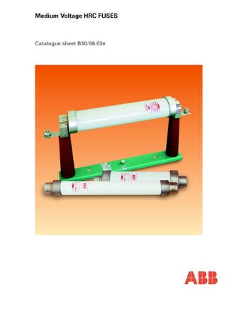
  • 1. Medium Voltage HRC FUSES Catalogue sheet B30/06.03e
  • 2. 1. FEATURES − High rupturing capacity − Short−circuit current limiting − Low rated minimum breaking current (Imin) − Low switching overvoltages (Um) − Can be used with switch disconnector (it is fitted with a medium−size striker pin) − Dimensions acc. to DIN and IEC Standards. 2. APPLICATIONS The HRC (high rupturing capacity) fuse−links are used to protect transformers, capacitor banks, cable and overhead lines against short−circuits. They protect switchgears from thermal and electromagnetic effects of heavy short−circuit currents by limiting the peak current values (cut−off characteristic) and interrupting the currents in several milliseconds. The type BWMW fuse−links interrupt overload currents greater than Imin (for the Imin values refer to Table 1). In situations where overloads lower than Imin are to be interrupted by the protective system, a switch− disconnector fitted with an overcurrent protecting device is to be used together with the type BWMW fuse−links. BWMW fuse−links can be used with type BWMP, BWMPE, BWMPNS, BWMPNW and BPS−01 fuse−bases as well as type OR5 or NALF switch−disconnectors. 3. ENVIRONMENTAL OPERATING CONDITIONS BWMW fuse−links can be operated under the following environmental conditions: − on indoor and outdoor equipment, − at ambient temperatures of −30oC to +40oC, − at relative humidity of ambient air of 100% at a temperature of +20oC. 4. DESIGNATIONS VERSIONS 4.1 BWMW−fuse−links numbering system The numbering system for the BWMW fuse−links has four alphanumerical sections as shown in the diagram below. 4.2 BWMP−fuse−base numbering system The numbering system for the BWMP fuse−base has four alphanumerical sections as shown in the diagram below. BWMW − 7,2 / 100 – 1 Fuse−link Rated Rated Additional type voltage current designation: BWMW 7,2−7,2 kV 3,15 A 12−12 kV 6,3 A 24−24 kV 10 A 36−36 kV 16 A 20 A 25 A 31,5 A 40 A 56 A 63 A 80 A 100 A Type BWMW 7,2 /63;80;100 A Fuse−links version that is 292 mm long BWMP E − 7,2 / 56 Fuse base Insulator Rated Rated type type voltage current BWMP E − resin 7,2−7,2 kV 40 A NS − outdoor 12−12 kV 50 A porcelain 24−24 kV 56 A standing−insulator 36−36 kV 63 A NW − outdoor 100 A porcelain (Refer to Table 2) suspented insulator No designation − indoor porcelain insulator A fuse−link when mounted on its fuse−base makes a complete fuse. For a list of fuse bases refer to Table 2. 5. COMPLIANCE WITH STANDARDS The fuse−links meet the requirements of the following Standards: − Polish Standard PN−92/E−06110 − Polish Standard PN−86/E−06114 − International Standard IEC 282−1: 1994 − International Standard IEC 644 of 1979 − German Standard DIN 43625 − Russian Standard GOST 2213: 1979 The fuse−bases meet the requirements of the following Standards: − Polish Standard PN−77/E−06110 − International Standard IEC 282−1: 1994 − German Standard DIN 43625 6. HOW TO ORDER Order by specifying the product name, type symbol, rated voltage, rated current and quantity. All additional demands which are not listed in this Catalogue should be agreed with the manufacturer by means of an Inquiry where the sources of requirements (regulations, standards, etc.) are to be specified. 6.1 Order example 1. Type BWMW−7.2/100 High Rupturing Capacity Fuse− link for a rated voltage of 7.2 kV, a rated current of 100 A 2. Type BWMPNW−12/56 Outdoor Fuse−base for a rated voltage of 12 kV, a rated current of 56 A. − 20 pcs 3. Type BWMW−36/20 High Rupturing Capacity Fuse− link for a rated voltage of 36 kV, a rated current of 20 A 4. Type BWMPNS−36/40 Outdoor−Standing Fuse−base for a rated voltage of 36 kV, a rated current of 40 A. − 20 pcs. 2 ABB
  • 3. 7. SPECIFICATIONS 7.1 Fuse−links specifications Table 1. 10% The resistance are to be measured by a electrical bridge method or technical metod using measuring instrument with accuracy class not worse than 0.5% at an ambient temperature of t = 20oC ±2oC. ABB 3
  • 4. 7.2 Fuse− bases specifications Fuse−base type Rated voltage Rated current Rated frequency Weight Related fuse−link Un In f kV A Hz kg BWMP−7,2/56 7,2 56 5.4 BWMW−7,2/3,15 ¸56 BWMP−7,2/100 100 6.1 BWMW−7,2/63 ¸100 BWMP−12/56 12 56 5.6 BWMW−12/3,15 ¸56 BWMP−12/100 100 50;60 6.2 BWMW−12/63 ¸100 BWMP−24/50 24 50 8.7 BWMW−24/3,15 ¸50 BWMP−24/63 63 8.9 BWMW−24/63 BWMP−36/40 36 40 15.0 BWMW−36/3,15 ¸40 BWMPE−7,2/56 7,2 56 3.4 BWMW−7,2/3,15 ¸56 BWMPE−7,2/100 100 4.1 BWMW−7,2/63 ¸100 BWMPE−12/56 12 56 3.6 BWMW−12/3,15 ¸56 BWMPE−12/100 100 50;60 4.2 BWMW−12/63 ¸100 BWMPE−24/50 24 50 4.8 BWMW−24/3,15 ¸50 BWMPE−24/63 63 5.0 BWMW−24/63 BWMPE−36/40 36 40 6.2 BWMW−36/3,15 ¸40 BWMPNS−7,2/56 7,2 56 BWMW−7,2/3,15 ¸56 BWMPNS−7,2/100 100 BWMW−7,2/63 ¸100 BWMPNS−12/56 12 56 BWMW−12/3,15 ¸56 BWMPNS−12/100 100 50;60 BWMW−12/63 ¸100 BWMPNS−24/50 24 50 17.6 BWMW−24/3,15 ¸50 BWMPNS−24/63 63 18.1 BWMW−24/63 BWMPNS−36/40 36 40 27.4 BWMW−36/3,15 ¸40 BWMPNW−7,2/56 7,2 56 BWMW−7,2/3,15 ¸56 BWMPNW−7,2/100 100 BWMW−7,2/63 ¸100 BWMPNW−12/56 12 56 BWMW−12/3,15 ¸56 BWMPNW−12/100 100 50;60 BWMW−12/63 ¸100 BWMPNW−24/50 24 50 17.6 BWMW−24/3,15 ¸50 BWMPNW−24/63 63 18.1 BWMW−24/63 BWMPNW−36/40 36 40 27.4 BWMW−36/3,15 ¸40 Table 2 BWMP An indoor fuse−base with porcelain insulators BWMPE An indoor fuse−base with resin insulators BWMPNS An outdoor fuse−base with porcelain insulators BWMPNW An outdoor suspended fuse−base with porcelain insulators 4 ABB
  • 5. Type BWMW high−rupturing−capacity fuse−link F−L Striker Pin Characteristic Striker Pin free stroke is 4 mm Notes: 1. Contact End Caps: silver−plated brass 2. Deviations of dimensions with no tolerance specified shall be within ±3%. ABB 5
  • 6. 8. CONSTRUCTION AND OPERATION 8.1 Construction and operation of fuse−links A fuse−link consists of an insulation tube whose both ends are terminated with end caps. Fuse elements are made from specially profiled silver wire and are helically wound on a porcelain winding stick. Additional fusible element intended to control operation of the striker pin is located in a coaxial hole of the stick. The fuse interior is filled with arc−quenching material whose chemical composition and granularity have been appropriately chosen. The fuse−link is sealed at its both ends. A spring−type striker pin is located in one end−cap and its forced movement can be employed to trip an operating mechanism of a switch−disconnector or to trigger alarm and auxiliary circuits. The fuse operation depends on automatic one−off interruption of the fault current in the protected circuit by melting of the fuse element and quenching the electric arc produced in the fuse−link interior. The operation is indicated by the striker pin which has now moved to its tripped position. The fuse−link limits the peak value of the short−circuit current and in consequence effectively protects the circuit against thermal and electromagnetic effects of short−circuits. 8.2 Construction of fuse bases The fuse−base consists of a steel beam fitted with a protective earthing terminal and two indoor support insulators. Two sets of contacts are mounted on the upper side of the insulator. The set of contacts consists of a contact spring, compression spring, and terminals. 9. PRINCIPLES OF FUSE−LINKS SELECTION 9.1 Selection of rated voltage The rated voltage for a fuse−link is to be selected in the following way: − if the fuse−link is to be operated in an earthed neutral three−phase network, the rated voltage for the fuse−link is to be equal to at least line−to−line voltage in the circuit to be protected, − if the fuse−link is to be operated in a single−phase network, the rated voltage for the fuse−link is to be equal to at least 115% of the highest voltage in the circuit to be protected, − if the fuse−link is to be operated in an insulated neutral three−phase network or a network compensated by means of earth fault neutraliser, the rated voltage for the fuse− link is to be equal to at least 115% of the line−to−line voltage in this network as double earth faults are possible. It should be however noted that in situations where a fuse−link featuring an excessive rated voltage has been selected, excessively high voltages for the circuit under consideration might occur. Refer to Table 1 for the limiting overvoltage values for this family of fuse−links. Should it be necessary to obtain more detailed data on the overvoltages, please call the fuse manufacturer. 9.2 Selection of rated current The rated current of a fuse−link is usually greater than a long−term load for the circuit under consideration. While selecting the rated current, the following should be taken into account. − long−term current load and operating overloads for the circuit under consideration, − transient overloads involved into such actions as switching power on and off for such equipment as transformers, electric motors, and capacitor banks, − co−ordination with other devices intended to protect the circuit under consideration. The rated current is determined by heating of a single fuse−link under free air conditions at an ambient temperature of +10oC to +40oC. In situations where the fuse−links are to be used in enclosures, cabinets and at places and in a manner making heat transfer more difficult or if the fuse−links are to operate at an ambient temperature higher than +35oC, lowering of the rated current value can be required to take the actual conditions of heat transfer into account. Refer to Table 3 for selection of fuse−links rated current recommended for protecting transformers. The selection presented above has been developed for a transformer overloaded up to 1.5 In when a condition of if01 > 12 In, is met, where: i f01 − minimum current value corresponding to a pre−arcing time of 0.1 sec. I n − rated voltage of the transformer 12 In; 0,1 sec. − parameters of the assumed making current for the transformer. However, in situations where actual making current value and waveform are known the fuse−link is to be selected individually. Besides, when a transformer protecting system is designed, the recommendations of IEC 787 Publication of 1983 is to be taken into consideration. It is suggested to test warm the equipment with fuses at a load of 1.5 In for the transformer to be protected particularly in cases where the correct selection is doubtful or the fuses are installed in a manner and at places (enclosures, cabinets, partitions, neat other heat sources, at higher ambient temperatures, and etc.) worsening the heat transfer. Section can be accepted as satisfactory if the produced steady state temperature−rise limits do not exceed the values permitted by respective standards. 6 ABB
  • 7. Table 3. Selection of fuse−links rated current for transformers Rated voltage of the transformer [kV] Transformer rated power [kVA] 6 10 15 20 30 Rated voltage for the fuse−link 7,2 12 17,5 24 36 Fuse−link rated current [A] 20 6,3 6,3 3,15 3,15 ¾ 30 6,3 6,3 6,3 3,15 3,15 50 10 6,3 6,3 6,3 3,15 75 16 10 6,3 6,3 6,3 100 20 16 10 6,3 6,3 125 20 or 25 16 10 or 16 10 6,3 160 25 20 16 10 10 200 40 20 16 16 10 250 56 31,5 20 16 10 315 56 31,5 or 40 25 20 16 400 63 40 or 56 25 or 31,5 20 16 500 80 56 40 25 25 630 100 63 56 31,5 25 800 ¾ 80 63 40 31,5 1000 ¾ 100 63 50 40 1250 ¾ ¾ ¾ 63 ¾ 9.3. Selection of the fuse−link rated current for electric motors – protection coordination principles 9.3.1 Selection of the fuse−link rated current for electric motors in a direct−on−line starting arrangement Electric motors by protected with switches (contactors, switch disconnectors) fitted with operating mechanisms and are additionally protected by fuses of specially selected characteristics. The fuse−link must be fitted with striker pin whose mechanical energy is used to trigger the switch disconnector. Difficulty with selection of the rated current for fuse−links intended to protect electric motors in a direct−on−line starting arrangement consists in the necessary immunity of fuses to consecutive overload pulses of the motor− starting−up current. For the fuse selection requirements, tests, and regulations concerned with motor protection systems refer to IEC 644 Standard: 1979 and its Polish equivalent PN− 86/E−06114. The Types BWMW for rated voltages of 7.2 kV and 12 kV and rated current range of 63 A to 100 A meet the requirements of the Standards mentioned above with respect to their time−current curves and are featured by their k−factors determined by tests for a pre−arcing time of 10 sec. with characteristic accuracy taken into consideration according to these Standards. For the values of k−factors refer to Table 4. The k−factor is to be used for determining the overload curve of fuse−link. According to these Standards, the k−factor values determined for a pre−arcing time of 10 sec. is valid for motor starting−up periods of 5 to 60 sec if the rate of motor starts is not greater than 6 per hour and no more than two consecutive starts per hour are made provided that the peak value of the starting−up current is not greater than the full−load value multiplied by a factor of 6. ABB 7
  • 8. Table 4. k−factor Values Fuse−link Fuse type Un Dimension“L” k−factor for particular In kV mm 63 A 80 A 100 A BWMW − 7,2 7,2 292 0,56 0,55 0,56 442 0,60 0,60 0,60 BWMW − 12 12 537 0,60 0,59 0,59 According to these Standards, the k−factor values determined for a pre−arcing time of 10 sec. is valid for motor starting−up periods of 5 to 60 sec if the rate of motor starts is not greater than 6 per hour and no more than two consecutive starts per hour are made provided that the peak value of the starting−up current is not greater than the full−load value multiplied by a factor of 6. Thus, ‰ ‰ k · IIk · Iand If10 r f10 ns 6 where: I− motor starting−up current, r Table 5. if and irmax, values against s−up periods Ins − motor full−load current if01 − fusing current as read in the fuse−link time−current characteristic for a pre−arcing time of 10 seconds. If the actual starting−up period differs from 10 seconds, a value of if is to be read in the fuse−link time−current characteristic for a pre−arcing time equal to the actual starting−up period (within a range of 5 to 60 seconds) and substituted in the formula. To make the selection of fuse easier, Table 5 lists fusing current values, if, and corresponding motor starting−up current values, irmax against starting−up periods 5, 10, 20, 30, 40, and 60 seconds. Un In Dimension“L” Starting−up periods in seconds kV A mm A 5 10 20 30 40 60 63 I f 210 190 170 160 155 145 I r max =k×If 118 106 95 90 87 81 80 292 I f 300 270 240 230 215 205 I r max 165 148 132 126 118 113 100 I f 400 360 320 300 285 270 7,2 I r max 224 201 179 168 159 151 63 I f 220 200 180 170 165 160 I r max 132 120 108 102 99 96 80 442 I f 300 270 240 230 215 205 I r max 180 162 144 138 129 123 100 I f 370 330 300 280 265 250 I r max 222 198 180 168 159 150 63 I f 220 200 180 170 165 160 I r max 132 120 108 102 99 96 12 80 I f 300 270 240 230 215 205 557 I r max 177 159 142 136 127 121 100 I f 380 340 305 285 275 260 I r max 224 200 180 168 162 153 8 ABB
  • 9. Example „Select a fuse−link of 12 kV rated voltage to protect a motor having a starting−up current of Ir = 190 A and a starting−up period tr = 12 seconds for a rate of motor starts not greater than 6 per hour". First, you should compare the value of Ir to respective ones listed in Table 4. In our case these are 10 s and 20 s. By comparing the respective values it can be seen that the proper fuse−link is that having a current rating of 100 A because Ir max 10(200) > Ir (190) > Ir max 20(180) Accurate check can be done by calculating: Ir k If = = = 322 A (Where the value of k−factor has been read in Table 2 for 12 kV/100 A) and reading the pre−arcing time amounting to 14 s (thus, greater than tr = 12 s) from the appropriate time−current curve (here 12 kV/100 A). The full−load of the motor for the selected fuse−link should not exceed a value of Ir 6 190 0,59 190 6 Ins ‰ ‰ ‰ 31,7 A Note: The Types BWMW−7,2 kV / 63−100 A are available in two sizes of dimension „L” = 292 mm and 442 mm. Those longer ones (442 mm) should be selected if smaller rated minimum fusing current I min offers a special attraction while by selecting the shorter ones (292 mm) the fuses can be installed at a location of smaller space. The fuse−links selected in this way are intended for operating under standard environmental conditions specified for the types BWMW. Should it be necessary to install the fuse−links together with other devices in a closed enclosure it is necessary to check whether the ambient temperature of the enclosure interior does not exceed the permissible value of +35oC and, if necessary, a fuse−link of successive higher level of the rated current should then be selected. 9.3.2 How to select the rated current of fuse−link Intended to protect electric motors in an indirect starting arrangement Because the fuse−links intended to protect electric motors in an indirect starting arrangement are overloaded with excessive pulses of the motor−starting−up current, their rated current may be lower than that for the motor protection in a direct−on−line starting arrangement. Provision for keeping fuse−link temperature permanently within the permissive temperature−rise limits in long−term duty of the motor to be protected irrespectively of the operating overloads is a decisive selection factor. To provide satisfactory operation without simultaneous fast deterioration of the fuse−links in the motor circuit in an indirect starting arrangement, the fuse−link rated current should be always greater than the most severe load with operating overloads being taken into account. Therefore, it is recommended to select a rated current equal to the motor full−load current multiplied by a factor of 1.5 to 2. 9.4 How to select the rated breaking current (Iws) of a fuse−link The rated breaking current (Iws) of a fuse−link is to be equal to at least an initial fault current (Ip) at the location the fuse−link is installed. 9.5 How to Select the Rated Peak Current (determining the required electromagnetic strength of the devices protected by means of fuse−links) According to the requirements of Polish Standard PN−74/E−05002, the rated peak current insz should fulfil the following inequality condition insz Š iu where: iu − (prospective) impulse short circuit current. In situations where the fuse limits the value of prospective impulse short circuit current, a product Iogr × h is to be substituted instead of iu in the relation presented above. Where: Iogr − fuse cut−off current for the prospective impulse short circuit current.− Iu corresponding to the largest designed fuse− link. h − a factor depending on the fuse cut−off current characteristic band width. In situations where no accurate data is available, a h−factor = 1.5 is to be accepted. ABB 9
  • 10. Fig. 1 Cut−off current characteristics for the types BWMW−7,2; 12; 24; 36 kV high rupturing capacity fuse−links 10 ABB
  • 11. time current Fig. 2 Time−current characteristics for the types BWMW−7,2/3.15−100 A (63 A excluded; dimension L = 292 mm); BWMW−12/3,15−40A and 63 A and 80 A Fuse−links I3 Current Designations: ❍ − BWMW−7.2 kV Fuse−links ● − BWMW−12 kV Fuse−links time current Fig. 3 Time−current characteristics for the types BWMW−7,2/63A (dimension L = 292 mm); BWMW−24/3,15−63A; BWMW−12/56 and 100 A; and BWMW−36/3,15−40 A Fuse−links I3 Current Designations: ❍ − BWMW−7.2 kV Fuse−links − BWMW−24 kV Fuse−links ● − BWMW−12 kV Fuse−links − BWMW−36 kV Fuse−links ABB 11
  • 12. Type BWMP indoor high−rupturing−capacity fuse−base Two 15 mm dia. holes Notes: 1. Earthing Terminal; tinned steel. 2. Connections: silver−plated brass 3. Contact Springs: silver−plated brass 4. Deviations of dimensions with no tolerance specified shall be within ±3%. Fuse−base Dimensions type A3 A2 A1 B2 B1 C1 ÆD BWMP−36/40 380±1 688±1 538±1 329±1 394±1 BWMP−24/63 BWMP−24/50 300±1 593±1 443±1 239±1 304±1 BWMP−12/100 380±1 688±1 538±1 0 105 85 75 BWMP−7,2/100 300±1 593±1 443±1 BWMP−12/56 180±1 445±1 293±1 159±1 224±1 BWMP−7,2/56 55±1 345±1 193±1 35±1 12 ABB
  • 13. Type BWMPE indoor high−rupturing−capacity fuse−base Two 15 mm dia. holes Notes: 1. Earthing Terminal; tinned steel. 2. Connections: silver−plated brass 3. Contact Springs: silver−plated brass 4. Deviations of dimensions with no tolerance specified shall be within ±3%. ÆD 70 56 Fuse−base Dimensions type A3 A2 A1 B2 B1 C1 BWMPE−36/40 380±1 688±1 538±1 326±1 398±1 BWMPE−24/63 BWMPE−24/50 300±1 593±1 443±1 236±1 308±1 BWMPE−12/100 380±1 688±1 538±1 0 BWMPE−7,2/100 300±1 593±1 443±1 156±1 228±1 BWMPE−12/56 180±1 445±1 293±1 BWMPE−7,2/56 55±1 345±1 193±1 35±1 ABB 13
  • 14. Type BWMPNS outdoor−standing high−rupturing−capacity fuse−base Two 15 mm dia. holes Notes: 1. Earthing Terminal; tinned steel. 2. Connections: silver−plated brass 3. Contact Springs: silver−plated brass 4. Deviations of dimensions with no tolerance specified shall be within ±3%. ÆD Fuse−base Dimensions type A4 A3 A2 A1 B2 B1 C1 BWMPNS−36/40 723±1 380±1 644±1 538±1 474±1 542±1 155 BWMPNS−24/63 708±1 334±1 402±1 BWMPNS−24/50 613±1 300±1 549±1 443±1 BWMPNS−12/100 708±1 380±1 644±1 538±1 BWMPNS−7,2/100 613±1 300±1 549±1 443±1 244±1 312±1 140 0 BWMPNS−12/56 463±1 180±1 399±1 293±1 BWMPNS−7,2/56 363±1 55±1 299±1 193±1 35±1 14 ABB
  • 15. Type BWMPNW outdoor−suspension high−rupturing−capacity fuse−base Two 15 mm dia. holes Notes: 1. Earthing Terminal; tinned steel. 2. Connections: silver−plated brass 3. Contact Springs: silver−plated brass 4. Deviations of dimensions with no tolerance specified shall be within ±3%. ÆD Fuse−base Dimensions type A4 A3 A2 A1 B2 B1 C1 BWMPNW−36/40 723±1 380±1 644±1 538±1 474±1 542±1 155 BWMPNW−24/63 708±1 334±1 402±1 BWMPNW−24/50 613±1 300±1 549±1 443±1 BWMPNW−12/100 708±1 380±1 644±1 538±1 0 BWMPNW−7,2/100 613±1 300±1 549±1 443±1 244±1 312±1 140 BWMPNW−12/56 463±1 180±1 399±1 293±1 BWMPNW−7,2/56 363±1 55±1 299±1 193±1 35±1 ABB 15