1. Types of NDT
• Visual
• Ultrasonic
Non-Destructive Testing (NDT) • X-ray
• Thermographic
ver 1 • Acoustic Emission
• Eddy Current
• Shearography
ENG 4793: Composite Materials and Processes 1 ENG 4793: Composite Materials and Processes 2
Visual Inspection Visual Inspection Equipment
• Basic principle:
– illuminate the test specimen with light • Magnifying Glass
– examine the specimen with the eye • Magnifying Mirror
• Used to: • Microscope
– to magnify defects which can not be detected by
the unaided eye • Borescope
– to assist in the inspection of defects – endoscopes or endoprobes
– to permit visual checks of areas not accessible to • Flexible Fiber Optic Borescope
unaided eye – working lengths are normally 60 to 365 cm with
• Most widely used of all the nondestructive tests. diameters from 3 to 12.5 mm
• Simple, easy to apply, quickly carried out and usually • Video Imagescope
low in cost.
ENG 4793: Composite Materials and Processes 3 ENG 4793: Composite Materials and Processes 4
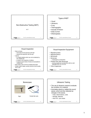
Borescopes Ultrasonic Testing
• The use of ultrasonic waves to evaluate
the condition of a material.
• Anomalies absorb or deflect the sound
waves, which are then detected as
changes in the waves.
– holes, delaminations, voids
Rigid Flexible fiber optic – damage, debonds
– resin-rich, -poor areas
ENG 4793: Composite Materials and Processes 5 ENG 4793: Composite Materials and Processes 6
1
2. Reflected (pulse-echo) Transmission
Through Transmission Mode
Mode
emitter - detector - transceiver
emitter
part part
reflector
detector
ENG 4793: Composite Materials and Processes 7 ENG 4793: Composite Materials and Processes 8
Ultrasonic Test Equipment A-scan
C-scan (single pulse - ice pick)
• Received pulse amplitude is represented as a
displacement along one axis and the travel
time of the ultrasonic pulse is represented as
a displacement along the other axis.
• A-scan displays are more complex because
all reflections are displayed, so signals (back
wall, waterpath) need careful interpretation.
ENG 4793: Composite Materials and Processes 9 ENG 4793: Composite Materials and Processes 10
A-scan B-scan
(cross section)
• A two-dimensional graphical
presentation, in rectangular coordinates,
in which the travel time of an ultrasonic
pulse is represented as a displacement
along one axis, and transducer
movement is represented as a
displacement along the other axis.
ENG 4793: Composite Materials and Processes 11 ENG 4793: Composite Materials and Processes 12
2
3. B-scan C-scan
(defect location map)
• A two-dimensional graphical presentation, in
which the discontinuity echoes are displayed
in a top view on the test surface.
• This method is applied to pulse-echo and
through transmission techniques.
• Usually no indication of depth is given unless
the complete scan represents the time of
flight evaluation (D-scan).
ENG 4793: Composite Materials and Processes 13 ENG 4793: Composite Materials and Processes 14
C-scan C-scans
ENG 4793: Composite Materials and Processes 15 ENG 4793: Composite Materials and Processes 16
3D C-scan C-scan test block
ENG 4793: Composite Materials and Processes 17 ENG 4793: Composite Materials and Processes 18
3
4. D-scan
D-scan
(defect depth map)
• A two-dimensional graphical
presentation, in which the time-of-flight
values are displayed in a top view on
the test surface. This is a modified C-
scan in which are amplitudes displayed.
ENG 4793: Composite Materials and Processes 19 ENG 4793: Composite Materials and Processes 20
D-scan of Test Block
Performance
• 5-25 MHz typical
• 0.2- 800 MHz possible
• Trade-off between frequency
(resolution) and depth of penetration
– higher frequency, better resolution, lower
depth of penetration
ENG 4793: Composite Materials and Processes 21 ENG 4793: Composite Materials and Processes 22
X-ray Technique Microfocus X-ray Technique
Film pack
Film pack
or X-ray imaging
or X-ray imaging
system
system
Test object
X-ray source Test object Greatly enlarged
Microfocus image
X-ray source
ENG 4793: Composite Materials and Processes 23 ENG 4793: Composite Materials and Processes 24
4
5. Microfocus X-ray Equipment Real Time X-ray Technique
Fluorescent
screen TV Monitor
camera scope
Intensifier Image
X-ray source processor
Test object
ENG 4793: Composite Materials and Processes 25 ENG 4793: Composite Materials and Processes 26
X-ray Images X-ray Images
IC chip Computer mouse Cooling lines in turbine blade
Porosity in weld
ENG 4793: Composite Materials and Processes 27 ENG 4793: Composite Materials and Processes 28
CT Scan CT Scanner
• CT produces 3-dimensional images of objects
using x-rays.
• The scanner, made in the shape of a ring,
contains an x-ray tube that circles the object.
The object in the scanner is bombarded by x-
rays from various angles and resulting
information signals are then processed by a
computer, yielding cross sectional slices
which then make up images.
ENG 4793: Composite Materials and Processes 29 ENG 4793: Composite Materials and Processes 30
5
6. CT Scan Images Restrictions
• Radio opaque penetrant sometimes
needed, as many composites are
transparent even to low energy X-rays
15 - 25 kV
– zinc iodide
– tetrabromoethane
– diiodobutane
• Cannot detect fiber breaks
ENG 4793: Composite Materials and Processes 31 ENG 4793: Composite Materials and Processes 32
Thermographic Principle Thermographic Technique
• Heat flow in a material is altered by the
presence of some types of anomalies.
• These changes in heat flow cause
localized temperature differences in the
material.
• Slow heating of part reveals these
Heat
anomalies. source Part IR camera
ENG 4793: Composite Materials and Processes 33 ENG 4793: Composite Materials and Processes 34
Thermography Images Acoustic Emission Principle
• Sounds made by a material, structure, or
machine in use or under load are heard and
analyzed to determine its "state of health".
• One or more ultrasonic microphones are
attached to the object and the sounds are
analyzed using computer based instruments.
• Noises may arise from:
– friction (including bearing wear)
PC board
– crack growth
Aircraft wing – material changes (such as corrosion)
ENG 4793: Composite Materials and Processes 35 ENG 4793: Composite Materials and Processes 36
6
7. Acoustic Emission Set-up
Acoustic Emission Technique
ENG 4793: Composite Materials and Processes 37 ENG 4793: Composite Materials and Processes 38
Acoustic Emission Advantages Acoustic Emission Applications
• Entire structure can be monitored from a few
locations. • pipelines
• Structure can be tested in use. • storage tanks (above and below the ground)
• Continuous monitoring with alarms is • fiberglass structures
possible. • rotating machinery
• Microscopic changes can be detected if • weld monitoring
sufficient energy is released. • biological and chemical changes
• Source location is also possible using
multiple sensors.
ENG 4793: Composite Materials and Processes 39 ENG 4793: Composite Materials and Processes 40
Eddy Current Principle Eddy Current Technique
• When an energized coil is brought near to the surface
of a metal or conducting component, eddy currents Eddy current
field Probe
are induced into the specimen. These currents set-up
magnetic field that tend to oppose the original
magnetic field. The impedance of coil in close
proximity to the specimen is affected by the presence
of the induced eddy currents in the specimen. Defect
• When the eddy currents in the specimen are distorted
by the presence of the flaws or material variations,
the impedance in the coil is altered. This change is
measured and displayed in a manner that indicates
the type of flaw or material condition.
ENG 4793: Composite Materials and Processes 41 ENG 4793: Composite Materials and Processes 42
7
8. Eddy Current Applications Shearography
• The object under study is illuminated by laser light,
• Range from crack detection, to the rapid and a camera produces two sheared images that
sorting of small components for either interfere with each other, causing a speckle pattern.
flaws, size variations, or material • When the object is deformed (sheared), the speckle
pattern changes.
variation.
• The two speckle patterns interfere to produce a fringe
• Commonly used in aerospace, pattern that depicts the surface gradient of the
automotive, marine, and manufacturing deformed object.
industries. • Though the images obtained are good, this method is
time-consuming.
ENG 4793: Composite Materials and Processes 43 ENG 4793: Composite Materials and Processes 44
Shearography Technique Shearography Images
Laser
Part
Shearography head Shear
and detector motion
Debonds
ENG 4793: Composite Materials and Processes 45 ENG 4793: Composite Materials and Processes 46
Summary
• Optical and Ultrasonic most widely used
techniques.
• Each has different principles and uses.
ENG 4793: Composite Materials and Processes 47 ENG 4793: Composite Materials and Processes 48
8