

Empfohlen
Empfohlen
Weitere ähnliche Inhalte
Was ist angesagt?
Was ist angesagt? (20)
Andere mochten auch
Andere mochten auch (16)
Ähnlich wie Principles of rock_drilling
Ähnlich wie Principles of rock_drilling (20)
Mehr von Saurabh Jain
Mehr von Saurabh Jain (9)
Kürzlich hochgeladen
Kürzlich hochgeladen (20)
Principles of rock_drilling
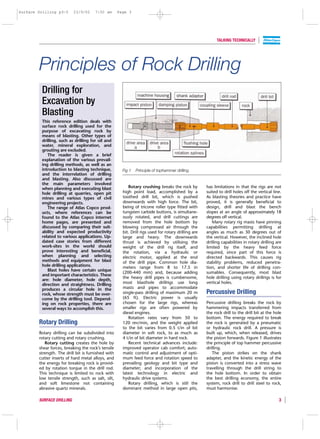
- 1. Surface Drilling p3-5 23/9/02 7:50 am Page 3 TALKING TECHNICALLY Principles of Rock Drilling Drilling for Excavation by Blasting This reference edition deals with surface rock drilling used for the purpose of excavating rock by means of blasting. Other types of drilling, such as drilling for oil and water, mineral exploration, and grouting are excluded. The reader is given a brief explanation of the various prevail- ing drilling methods, as well as an introduction to blasting technique, Fig 1 Principle of tophammer drilling. and the interrelation of drilling and blasting. Also discussed are the main parameters involved when planning and executing blast Rotary crushing breaks the rock by has limitations in that the rigs are not hole drilling at quarries, open pit high point load, accomplished by a suited to drill holes off the vertical line. mines and various types of civil toothed drill bit, which is pushed As blasting theories and practice have engineering projects. downwards with high force. The bit, proved, it is generally beneficial to The range of Atlas Copco prod- being of tricone roller type fitted with design, drill and blast the bench ucts, where references can be tungsten carbide buttons, is simultane- slopes at an angle of approximately 18 found to the Atlas Copco internet ously rotated, and drill cuttings are degrees off vertical. home pages, are presented and removed from the hole bottom by Many rotary rig masts have pinning discussed by comparing their suit- blowing compressed air through the capabilities permitting drilling at ability and expected productivity bit. Drill rigs used for rotary drilling are angles as much as 30 degrees out of related to various applications. Up- large and heavy. The downwards the vertical. However, the inclined hole dated case stories from different thrust is achieved by utilising the drilling capabilities in rotary drilling are work-sites in the world should weight of the drill rig itself, and limited by the heavy feed force prove interesting and beneficial, the rotation, via a hydraulic or required, since part of this force is when planning and selecting electric motor, applied at the end directed backwards. This causes rig methods and equipment for blast of the drill pipe. Common hole dia- stability problems, reduced penetra- hole drilling applications. meters range from 8 to 17.5 in tion, and shorter life of drilling con- Blast holes have certain unique (200-440 mm) and, because adding sumables. Consequently, most blast and important characteristics. These the heavy drill pipes is cumbersome, hole drilling using rotary drillrigs is for are: hole diameter, hole depth, direction and straightness. Drilling most blasthole drillrigs use long vertical holes. produces a circular hole in the masts and pipes to accommodate rock, whose strength must be over- single-pass drilling of maximum 20 m Percussive Drilling come by the drilling tool. Depend- (65 ft). Electric power is usually ing on rock properties, there are chosen for the large rigs, whereas Percussive drilling breaks the rock by several ways to accomplish this. smaller rigs are often powered by hammering impacts transferred from diesel engines. the rock drill to the drill bit at the hole Rotation rates vary from 50 to bottom. The energy required to break Rotary Drilling 120 rev/min, and the weight applied the rock is generated by a pneumatic to the bit varies from 0.5 t/in of bit or hydraulic rock drill. A pressure is Rotary drilling can be subdivided into diameter in soft rock, to as much as built up, which, when released, drives rotary cutting and rotary crushing. 4 t/in of bit diameter in hard rock. the piston forwards. Figure 1 illustrates Rotary cutting creates the hole by Recent technical advances include: the principle of top hammer percussive shear forces, breaking the rock’s tensile improved operator cab comfort; auto- drilling. strength. The drill bit is furnished with matic control and adjustment of opti- The piston strikes on the shank cutter inserts of hard metal alloys, and mum feed force and rotation speed to adapter, and the kinetic energy of the the energy for breaking rock is provid- prevailing geology and bit type and piston is converted into a stress wave ed by rotation torque in the drill rod. diameter; and incorporation of the travelling through the drill string to This technique is limited to rock with latest technology in electric and the hole bottom. In order to obtain low tensile strength, such as salt, silt, hydraulic drive systems. the best drilling economy, the entire and soft limestone not containing Rotary drilling, which is still the system, rock drill to drill steel to rock, abrasive quartz minerals. dominant method in large open pits, must harmonise. SURFACE DRILLING 3
- 2. Surface Drilling p3-5 23/9/02 7:50 am Page 4 TALKING TECHNICALLY Stress Wave Piston 1 Piston 1 Fig 5 Stress level – 0,8 MPa generated by different Theoretically, the stress wave has a rec- – 8 bar pistons of same tangular shape, the length of which is weight. twice that of the piston, while the Piston 2 ––12 MPa Piston 2 120 bar height depends on the speed of the piston at the moment of impact, and on the relationship between the cross- sectional area of the piston and that of Piston 3 ––20 MPa Piston 3 200 bar the drill steel. s 5200 m/s + – 2 x piston length Fig 2 Stress wave energy. 3 2 The total energy that the wave contains is indicated diagramatically in 1 Figure 2. To calculate the output power obtained from a rock drill, the Shock-wave amplitude wave energy is multiplied by the impact frequency of the piston, and is usually stated in kW. Rock drill The shock waves that are generated When the shock wave reaches the designers seek to find the best com- by hydraulic (Figure 3) and pneumatic bit, it is forced against the rock, there- binations of various parameters, such (Figure 4) rock drills are significantly by crushing it. The efficiency at the bit as the piston geometry, the impact different in shape. Drill rods used with never reaches 100%, because some of rate and the frequency. Two rock drills hydraulic rock drills will normally show the energy is reflected as a tensile having the same nominal power rating substantially longer service life, com- pulse. The poorer the contact between might therefore have quite different pared with pneumatic rock drills, the bit and the rock, the poorer the properties. because of the higher stress level efficiency (Figure 6). obtained with the pneumatic driven piston. s Reflecting wave s The reason is the larger cross- section needed when operating at + + substantially lower pressure, which is – – 6-8 bars, compared to the 150-250 bars used with hydraulic systems. The slimmer the piston shape, the lower Primary wave the stress level. Figure 5 compares the stress level generated by three different pistons Fig 6 Poor contact between bit and rock having the same weight, but with dif- results in poor efficiency. ferent shapes and working at different Fig 3 Shock wave generated by pressures. The lowest stress, or shock hydraulic rock drill. wave amplitude, is obtained with the To optimise drilling economy, the long slender piston working at high drilling parameters for percussion s pressure. pressure, feed force, and rotation must harmonise. + Efficiency and Losses – Percussion Pressure The wave loses some 6-10% of its energy for every additional coupling, The higher the pressure, the higher as it travels along the drill string. This will be the speed of the piston, and loss is partly due to the difference in consequently, the energy. Where the cross-sectional area between the rod bit is in good contact with hard and and the sleeve, and partly due to competent rock, the shock wave Fig 4 Shock wave generated by imperfect contact between the rod energy can be utilised to its maximum. pneumatic rock drill. faces. The poorer the contact, the Conversely, when the bit has poor greater the energy loss. contact, the energy cannot leave the 4 SURFACE DRILLING
- 3. Surface Drilling p3-5 23/9/02 7:50 am Page 5 TALKING TECHNICALLY Percussion pressure Percussion pressure Hydraulic Drilling method Tophammer DTH COPROD hole diameter, mm 76-127 85-165 105-165 penetration rate 2 1 3 hole straightness 1 3 3 Soft rock Hard rock hole depth 1 3 3 production capacity (tons rock/shift) 2 1 3 Fig 7 To reduce reflected energy, fuel consumption/drill metre 2 1 2 percussion pressure is lowered. service life of drill string 1 2 3 investment in drill string 2 2 1 drill string, and reverses up the drill suitability for good drilling conditions 3 2 2 string as a tensile wave. It is only when drilling in sufficiently suitability for difficult drilling conditions 1 3 3 hard rock that the maximum energy simplicity for operator 2 3 1 per blow can be utilised. In soft rock, to reduce the reflected energy, adjustability of flushing capacity 1 2 3 the percussion pressure, and thus the energy, will have to be lowered Fig 9 Ratings are: fair = 1, good = 2, and very good = 3 (Figure 7). Comparison for 20 m bench drilling in a limestone quarry For any given percussion pressure, the amplitude, and hence the stress in between blows. Consequently, the power output from rock drills in- the drill steel, will be higher with rotation rate is increased using higher creases, accompanied by increased reduced cross-section of the drill rods. impact frequency and reduced bit penetration rate, efficient flushing To get the longest possible service life diameter. Using insert bits, the recom- becomes gradually more important. from shank adapters and rods, it is mended rotation rate is 25% higher. The flushing medium is normally air important to ensure that the working for surface drilling, and water for pressure is matched to the drill string Setting Parameters underground drilling. at all times. The required flushing speed will In practice, the driller sets the percus- depend on: specific gravity – material Feed Force sion pressure that the rock can cope having a density of 2 t/cu m requires with, and then sets the rev/min with at least 10 m/sec, whereas iron ore, for The purpose of the feed is to maintain regard to the percussive frequency and example, having a density of 4 t/cu m, the drill bit in close contact against the the bit diameter. requires an air speed of 25-30 m/sec; rock. However, the bit must still be When drilling starts, the feed is particle size – the larger the particles, able to rotate. The feed force must adjusted to get even and smooth rota- the higher flushing speed required; always be matched to the percussion tion. In case this is not achieved, which particle shape – spherical particles pressure. Figure 8 illustrates this will show up in low shank adapter require more speed than flaky, leaf relationship. life, the percussion pressure can be shaped particles. progressively reduced, until even and Feeding smooth rotation is reached. Productivity and Methods The temperature of the adapter sleeve can be checked to ensure that During the past century there has the drilling parameters are correctly been a rapid and impressive increase set. Immediately after drilling, the tem- in efficiency and productivity related perature should be 60-70 degrees for to top hammer drilling. Starting dry drilling, and approximately 40 from hitting a steel manually by a degrees for wet drilling. sledge hammer 100 years ago, Low percussion High percussion Drilling problems, mainly related to today’s hydraulically powered rock pressure pressure loose couplings, may arise whatever drills utilise the latest state-of-the-art parameters are used. In order to tight- technology. en the couplings during drilling, the Every drilling method has its pros Fig 8 Feed force must be matched to friction of the bit against the hole and cons, making an objective com- percussion pressure. bottom has to be increased. This can parison quite cumbersome. In view be done by increasing the feed, of this, the table in figure 9 can serve increasing the rotation rate, or chang- as a guideline when comparing the ing the bit. various percussion drilling alternatives Rotation which Atlas Copco can offer. The Flushing choice of best drilling method to apply The purpose of rotation is to turn the depends on hole size and type of drill bit to a suitable new position for Drill cuttings are removed from the application. the next blow. Using button bits, the hole bottom to the surface by air periphery is turned about 10 mm blowing or water flushing. As the by Hans Fernberg SURFACE DRILLING 5