1. J O U R N A L O F T H E M E C H A N I C A L B E H AV I O R O F B I O M E D I C A L M AT E R I A L S
1 (2008) 76–85
available at www.sciencedirect.com
journal homepage: www.elsevier.com/locate/jmbbm
Research paper
Mechanical strength of abalone nacre: Role of the soft organic
layer
Marc André Meyers ∗ , Albert Yu-Min Lin, Po-Yu Chen, Julie Muyco
Department of Mechanical and Aerospace Engineering, Materials Science and Engineering Programme, University of California, San Diego,
La Jolla, CA 92093-0411, USA
A R T I C L E I N F O
A B S T R A C T
Article history:
The nacreous portion of the abalone shell is composed of calcium carbonate crystals
Received 31 January 2007
interleaved with layers of viscoelastic proteins. The resulting structure yields unique
Received in revised form
mechanical properties. In this study, we focus on the thin viscoelastic layers between
7 March 2007
the tiles and on their role on the mechanical properties of the shell. Both SEM and AFM
Accepted 8 March 2007
show that the thin (∼30 nm) organic layer is porous, containing holes with diameter
Published online 29 May 2007
of approximately 50 nm. These holes enable the formation of mineral bridges between
adjacent tile layers. The mineral bridges play a pivotal role in growth and ensure the
maintenance of the same crystallographic relationship through tile growth in the ‘terraced
cone’ mode. The existence of mineral bridges is consistent with the difference between
tensile and compressive strength of the abalone. Mechanical tests with loading applied
perpendicular to the plane of the organic layers reveal a tensile strength lower than 10
MPa, whereas the compressive strength is approximately 300–500 MPa. These nanoscale
bridges have, by virtue of their dimensions (50 nm diameter × 30 nm length), a strength
that reaches their theoretical value. The calculated tensile strength based on the theoretical
strength predicts a bridge density of approximately 2.25/µm2 .
A major conclusion of this investigation is that the role of the organic layer is primarily
to subdivide the CaCO3 matrix into platelets with thickness of 0.5 µm. Its intrinsic effect in
providing a glue between adjacent tiles may not be significant.
c 2007 Elsevier Ltd. All rights reserved.
1.
Introduction
The abalone shell has two layers: an outer prismatic
layer (rhombohedral calcite) and an inner nacreous layer
(orthorhombic aragonite). Aragonitic CaCO3 constitutes the
inorganic component of the nacreous ceramic/organic
composite (95 wt% ceramic, 5 wt% organic material). This
composite comprises stacked platelets (∼0.5 µm thick),
arranged in a ‘brick-and-mortar’ microstructure with an
∗ Corresponding author. Tel.: +1 858 534 4719; fax: +1 858 534 5698.
E-mail address: mameyers@ucsd.edu (M.A. Meyers).
1751-6161/$ - see front matter c 2007 Elsevier Ltd. All rights reserved.
doi:10.1016/j.jmbbm.2007.03.001
organic matrix (20–50 nm thick) interlayer that is traditionally
considered as serving as glue between the single platelets.
There is a very high degree of crystallographic texture
characterized by a nearly perfect “c-axis” alignment normal
to the plane of the tiles. As a result of its highly ordered
hierarchical structure (Laraia and Heuer, 1989; Vincent, 1991;
Baer et al., 1992; Srinivasan et al., 1991; Heuer et al., 1992;
Sarikaya, 1994; Mayer and Sarikaya, 2002), the nacreous layer
exhibits excellent mechanical properties.
2. J O U R N A L O F T H E M E C H A N I C A L B E H AV I O R O F B I O M E D I C A L M AT E R I A L S
There is a second element to the hierarchy: growth bands,
or mesolayers. Layers of organic material with a thickness
of about 20 µm separate the thicker mesolayers which are
approximately 300 µm thick. These layers were identified by
Menig et al. (2000), Su et al. (2002), and Lin and Meyers (2005)
but are not often mentioned in other reports dealing with
the mechanical properties of abalone. It is thought that these
thick organic layers form in abalone grown in the sea during
periods in which there is little growth.
Fig. 1a shows the inside surface (nacreous) of an abalone
shell. The cross-section shows the mesolayers, which are
spaced approximately 300 µm apart and are separated by
thick regions that consist of primarily organic material with
minerals embedded into it (Lin et al., 2006). The mineral
regions are comprised of the tiles discussed above; they are
separated by the organic nanolayers. The effectiveness of this
structure in increasing the toughness is demonstrated by the
SEM micrograph of the tiles being pulled apart in a fracture
region (lower left-hand side of Fig. 1a).
Currey (1977) was the first to perform measurements of
mechanical properties of nacre from a variety of bivalves,
gastropods and cephalopods. He obtained a fracture strength
in bending varying between 56 and 116 MPa. This was
followed by Jackson et al. (1988) who used nacre from the
shell of a bivalve mollusk, Pinctada. They reported a Young’s
modulus of approximately 70 GPa for dry and 60 GPa for
wet samples; the tensile strength of nacre was found to be
170 MPa for dry and 140 MPa for wet samples. The work
of fracture varied from 350 to 1240 J/m2 , depending on the
span-to-depth ratio and the degree of hydration, wet nacre
showing superior toughness by associated introduction of
plastic work. In contrast, monolithic CaCO3 showed a work
of fracture that was up to 3000 times less than that of
the composite nacre material. The work-of-fracture is the
area under the stress–strain curve and is deeply affected by
gradual, graceful fracture, whereas the fracture toughness
does not incorporate this entire process.
Mechanical tests on red abalone (Haliotis rufescens) were
conducted by Sarikaya et al. (1990), Sarikaya and Aksay (1992),
and Sarikaya (1994) and a fracture strength of 185 ± 20 MPa
(in bending tests) and a fracture toughness of 8 ± 3 MPa m1/2
were obtained. This latter value is an eight-fold increase in
toughness over monolithic CaCO3 . The scatter was explained
by the natural defects in the nacre and the somewhat
curved shape of the layers. Menig et al. (2000) applied
Weibull statistics (Weibull, 1951) and successfully explained
the variation. They obtained mean tensile strengths of 177
and 197 MPa for flexure testing parallel and perpendicular
to the surface plane, respectively. These results are in full
agreement with Jackson et al. (1988), Sarikaya et al. (1990),
Sarikaya and Aksay (1992), and Sarikaya (1994). Wang et al.
(2001) also determined the flexural tensile strength of red
abalone (H. rufescens) and obtained values of 194 and 223
MPa for loading (in flexure) parallel and perpendicular to
the surface plane. The compressive strength obtained by
Menig et al. (2000), on the other hand, was much higher
and equal to 540 and 235 MPa for loading perpendicular and
parallel to the layered structures. The low value obtained
in the parallel direction was attributed to the observation
of microplastic buckling (Menig et al., 2000). Thus, the ratio
1 (2008) 76–85
77
between compressive and tensile strength is in the range
1.5–3, in contrast with the conventional monolithic ceramics,
in which it is 8–15.
Several toughening mechanisms have been proposed by
Sarikaya et al. (1990), and Sarikaya and Aksay (1992): (a) crack
blunting/branching/deflection, (b) microcrack formation, (c)
plate pull out, (d) crack bridging (ligament formation). The
high degree of crack tortuosity in these shells may be
due mainly to crack blunting and branching. Menig et al.
(2000) also observed crack deflection at the mesolayers,
which have thick (20 µm) organic interfaces. Additional
toughening mechanisms such as sliding of CaCO3 layers and
organic ligament formation were thought to operate and
were analysed by Lin and Meyers (2005). Evans et al. (2001)
and Wang et al. (2001) proposed an alternative toughening
mechanism: that nano-asperities on the aragonite tiles
are responsible for the mechanical strength. These nanoasperities create frictional resistance to sliding, in a manner
analogous to rough fibers in composite material. They
developed a mechanism that predicts the tensile mechanical
strength based on these irregularities. These nano-asperities
were modelled by Barthelat et al. (2006), who carried
out nanoindentation and FEM analysis of the aragonite
crystals. Bruet et al. (2005) obtained, through nanoindentation
and atomic force microscopy, local measurements of the
mechanical properties of the aragonitic tiles: E = 79 and
92 GPa and compressive strengths of 11 and nine GPa for dry
and seawater soaked tiles, respectively.
The growth of the abalone shell has been the subject of
considerable past study. The work by the UC Santa Barbara
group (Fritz et al., 1994; Zaremba et al., 1996; Belcher, 1997;
Belcher et al., 1996, 1998; Belcher and Gooch, 2000; Shen
et al., 1997; Fritz and Morse, 1998) represents the most
comprehensive effort. The study whose results are presented
here is not concerned about the molecular structure of the
organic layer, but with the role of that layer in the overall
mechanical response of nacre.
2.
Experimental methods
A new method (‘trepanning’) was used for the observation
of growth mechanisms in nacre. It consists of (a) coring
out a cylindrical section of the abalone shell, (b) replacing
by one with slightly larger diameter, and (c) removing at
regular intervals to observe the restart of growth. It was
supplemented by the Santa Barbara flat pearl technique (Fritz
et al., 1994), which has been used previously by Lin and
Meyers (2005).
Both a FEI environmental SEM (Scripps Institute of
Oceanography) and a FEI field emission SEM were used
for characterization with accelerating voltages of 15–20 kV.
Samples were examined immediately after removal in
order to maintain hydration of the organic matrix. Before
examination, the slides and cylinders are usually washed
in purified water to remove salt build up. However, for
observation of the organic layer the washing procedure was
eliminated to preserve the organic growth material. The
AFM characterization on the organic layer was carried out
at Lawrence Livermore National Laboratory. The organic
3. 78
J O U R N A L O F T H E M E C H A N I C A L B E H AV I O R O F B I O M E D I C A L M AT E R I A L S
1 (2008) 76–85
Fig. 1 – (a) Overall view of hierarchical structure of abalone shell, showing mesolayers, mineral tiles, and tile pullout in a
fracture region. (b) Top growth surface six weeks after implantation. Light regions represent apexes of terraced cones and
streaks marked by arrows are due to folding of organic interlayer.
layers were separated from the aragonite tiles by EDTA
demineralization. Strips of the organic nanolayers were kept
in a saline solution until observation by AFM.
The abalone (both red and green) were held at the
Scripps Institution of Oceanography, in open system tanks in
which continuous fresh sea water (removed circulation) was
provided. They were fed kelp (Macrocystis pyrifera) on a regular
schedule. The specimens were removed at one week intervals
at times up to six weeks.
Mechanical testing was carried out in tension and
compression. The direction of both tensile and compression
loads was perpendicular to the large dimension of the tiles,
corresponding to the surface of the shell. For tensile testing
the specimens were extracted using a coring drill. They had
a diameter of 3 mm. The calcite layer was ground away until
the entire thickness consisted exclusively of aragonite tiles.
Two methods were used for tensile testing of the nacre with
loading perpendicular to the plane of the tiles. The upper
and lower surfaces of the specimens were glued to aluminum
holders and allowed to cure for 24 h with the loading
4. J O U R N A L O F T H E M E C H A N I C A L B E H AV I O R O F B I O M E D I C A L M AT E R I A L S
1 (2008) 76–85
79
assembly in place. The assembly was either mounted in an
Instron testing machine or at the extremity of a cantilever
beam so that no bending was applied to the specimen. The
breaking load was determined and the surfaces characterized
by SEM. The compression specimens were obtained through
two techniques: (a) cutting cubes from the shell using a
high speed diamond blade (Menig et al., 2000); (b) cylindrical
specimens prepared as described above.
3.
Results and discussion
3.1.
Growth arrest experiments
The top view of the growth surface after six weeks is shown
in Fig. 1b. The terraced cones can be seen, albeit not too
clearly, because they are covered by an organic layer. The tips
of the terraced cones (which we call Christmas trees) are the
lighter features, with a separation of 5–10 µm, corresponding
to the steady state tile diameter. Parallel lines (marked by
arrows) connect the tips of some cones. These parallel lines
are oriented at ∼30◦ to the horizontal axis of Fig. 1b. They
correspond to the folding of the organic layer. These folds,
three of which are marked by arrows A, have a thickness
of approximately 300 nm. The effect is analogous to the
folds formed on top of tents. Previous observation (Lin and
Meyers, 2005) of the growth surface after cleaning by water
did not reveal the organic layer. It is thought that even small
perturbations can remove this layer.
The growth sample was fractured in tension parallel to the
growth surface to enable a lateral observation of the structure
along the a and b direction of growth. This was done after
the structure was allowed to dry. The results are shown in
Fig. 2a. The structure is remarkably well retained. The top
corresponds to the growth surface and the bottom to the fully
interweaved tiles. The tips of the terraced cones protrude
through the top layer of the organic material. In places, such
as that which is marked with an arrow B, the organic material
is ruptured. This is presumably due to the drying process. The
folding of the organic membrane is also seen and is marked
by arrow A. Again, the features on the top three mineral layers
of the terraced cones are not clear because they are covered by
the organic layer. Fig. 2b is a schematic showing the sagging
of the membrane under its own weight.
Upon closer observation, the organic layer stretched
between tiles is seen to contain rings of holes (Fig. 3a). This
is in contrast with the top (growth) layer, which does not
show these holes (Fig. 1b and 2a). These holes are produced
by the stretching introduced during the fracturing process.
The holes have diameters which increase with the stretch.
Similar holes were also observed by Belcher and Gooch (2000)
(Figs. 15.1 and 15.9). These observations suggest that existing
holes expand upon stretching of the organic membrane.
Fig. 3b shows, in schematic fashion, an initially random
pattern of holes. Upon stretching the membrane biaxially, the
circumferential stresses at the edges of the holes experience
twice the applied stresses. Thus, the strain along them is
higher than the overall strain and the rate of growth of
the holes is larger than the overall strain (Fig. 3c). This
Fig. 2 – (a) Side view of intermediate tile growth through
organic layers on flat pearl five weeks after implantation.
(b) Schematic showing terraced growth and organic
membrane sagging under its own weight.
explains the presence of large holes (up to 400 nm) in severely
stretched layers.
Atomic force microscopy on the organic layer revealed
the outline of the tiles (Fig. 4a). One of the tiles is
schematically shown, for clarity. It should be mentioned that
the material was completely demineralized. This outline is
due to variations of morphology and thickness associated
with the tile boundaries. Higher magnification observation
in the tapping mode revealed the detailed structure of the
organic layer (Fig. 4b). There are two principal components:
long (Lustrin protein?) chains arranged in a random pattern;
holes with diameter 20–50 nm. The depth of the holes can be
gauged from the depth scale in the right-hand side of Fig. 4b.
The surface corresponds to 30 nm, and the holes correspond
to the baseline of the depth scale.
3.2.
Calculation of organic nanolayer stiffness from
deflection
The sagging of the organic layer, shown in Fig. 1b and 2a, can
be used to estimate its stiffness. The fact that the organic
membrane undergoes substantial sagging from the sole effect
of its weight suggests that its stiffness is very low. The sagging
of a membrane is a classical mechanics problem. We present
5. 80
J O U R N A L O F T H E M E C H A N I C A L B E H AV I O R O F B I O M E D I C A L M AT E R I A L S
1 (2008) 76–85
Fig. 4 – Atomic force microscopy of organic layer; (a) overall
view at low magnification showing outline of hexagonal
tiles; (b) high magnification showing linear chains and
holes with ∼30 nm diameter.
wmax =
Fig. 3 – (a) SEM of membranes with holes that formed
upon stretching; (b) schematic representation of membrane
with holes; (c) membrane subjected to biaxial stress.
ρhga2
4N
(1)
ρ is the density; N is the tensile force per unit length which is
represented by stress multiplied by unit thickness:
N = σh.
(2)
The biaxial stress in a membrane under its own weight is
here a solution applicable to the simple boundary conditions.
The membrane is assumed to be circular and fixed along the
circle. Its deflection as a result of its weight is calculated.
The radial forces are considered to be zero at zero deflection.
The equilibrium diagram is shown in Fig. 2b. The following
parameters are defined: a, radius of the membrane (assumed
to be circular); w, deflection; h, thickness of the membrane;
σ, radial stress on membrane. One finds that wmax , the
maximum deflection, can be expressed in terms of known
parameters (e.g. Ugural (1981), Szilard (2004)):
σ=
ρga2
.
4wmax
(3)
The nominal biaxial strain is defined as
ε=
L − 2a
.
2a
(4)
For the calculation of the strain, we assume θ, the angle
between the a–b plane of growth and the outer edges of the
sagging membrane, is small. Thus
∂w
wmax
sin θ ∼ tan θ =
=
=
∂r
a
(5)
6. J O U R N A L O F T H E M E C H A N I C A L B E H AV I O R O F B I O M E D I C A L M AT E R I A L S
Fig. 5 – Calculated (a) stress, and (b) elastic modulus of
organic layer as a function of deflection for two circle radii
(assumed shape between sagging points of the membrane)
are considered: 2.5 and 5 µm.
θ
θ
a2
L = 2πR
= 2π
.
180◦
wmax 180◦
(6)
We assume the density of the organic layer to be 1.5 g/cm3 .
The thickness of the membrane is taken to be 30 nm,
in accordance with several measurements reported in
the literature and our own approximate evaluation. Two
circle radii (assumed shape between sagging points of the
membrane) are considered: 2.5 and 5 µm. This is consistent
with tile size of approximately 5–10 µm. Fig. 5a shows the
stresses calculated using Eq. (3). The deflection, average
distance between the lowest point of the membrane and
the a–b plane of growth, is varied from zero to 0.6 µm. The
corresponding biaxial modulus, obtained by dividing Eq. (3) by
(4), is plotted in Fig. 5b. Although this is difficult to evaluate,
the deflection can be estimated from Fig. 2a. This deflection
varied somewhat and there are uncertainties that are beyond
the measure. One could argue that the dried membrane has
properties different from the original hydrated membrane.
However, it is thought that the drying process ‘freezes in’ the
existing configuration. Many other observations confirm the
extreme ‘softness’ of the layer, as well as its poor adherence
to the tiles. Taking a value of 0.5 µm, consistent with the
sagging shown in Fig. 2, one obtains a biaxial elastic modulus
1 (2008) 76–85
81
Fig. 6 – Weibull distribution of (a) tensile and (b)
compressive strengths with force direction perpendicular to
layered structure.
of 100 Pa, considering a tile spacing of 10 µm (a = 5 µm).
This is indeed a very low value. This low value can only be
explained if the random network of protein chains in Fig. 4b
can slide when tension is applied to the membrane. The
value of 100 Pa is an upper bound, and the range of elastic
moduli is comparable to that of other living cells (Bao and
Suresh, 2003). This value is also consistent with the high
maximum tensile strains that the organic layer can undergo
in tension. Belcher and Gooch (2000) (Fig. 15.9) quote a value
of εmax = 3 (equivalent to a maximum stretch λ = ε + 1 = 4).
The calculations confirm that the organic layer material has
a very small stiffness.
3.3.
Mechanical tests perpendicular to layer plane
As discussed in the introduction, there have been a considerable number of studies determining both compressive and
tensile strength along the tile plane (loading axis parallel to
shell surface). The determination of the shell strength when
the loading is applied perpendicular to its surface can directly address the role played by the organic layer. The results,
expressed as Weibull plots, are shown in Fig. 6a. For comparison, the compressive strength in the same orientation is
7. 82
J O U R N A L O F T H E M E C H A N I C A L B E H AV I O R O F B I O M E D I C A L M AT E R I A L S
1 (2008) 76–85
Fig. 7 – Various views of organic layer in specimen subjected to tensile test (field-emission SEM); (a, b) layers hanging
between two tiles (marked with arrow); (c, d) top view of tile surface with organic layer networks.
shown in Fig. 6b. The same distribution was observed previously in abalone and conch (Menig et al., 2000, 2001) shells.
The Weibull moduli in both tension and compression are similar: 1.6 and 1.8–2.5, respectively, as seen in Fig. 6a and b,
respectively. However, the difference in strength is dramatic
and much greater than in conventional brittle materials. The
ratio between compressive and tensile strength is of the order of 50, whereas brittle materials it varies between 8 and
12. This difference is indeed striking, especially if one considers the tensile strength parallel to the layer plane; it is on the
order of 150–200 MPa, one third of the compressive strength. It
should be mentioned that in composites this ratio in the fiber
direction is much more favourable; in this sense, the nacreous portion of the shell can be considered a composite. This
was discussed by Menig et al. (2000). It can be concluded that
the shell sacrifices tensile strength in the perpendicular direction to the tiles to use it in the parallel direction. Interestingly,
the average of the tensile strength (in the perpendicular and
parallel directions) is approximately 75–100 MPa, whereas the
compressive strength is approximately 500 MPa. This is much
closer to the ‘normal’ value for the ratio between compressive
and tensile strength of ceramics.
SEM characterization of the surfaces fractured in tension
reveals the failure path. For the most part, it occurs in
the inter-tile regions. Fig. 7a and b show fractured regions
with partial separation between tiles. Thin sections of the
organic layer, hanging between adjacent tile layers, are seen.
Although the detailed features could not be resolved, it is
clear that the organic layer is very soft. It is also apparent that
it is not firmly attached to the tiles. The field-emission SEM
enabled a resolution of down to 10 nm. Fig. 7c and d show
the top surfaces of tiles. Irregular features, the remnants
of the organic layer, can be seen attached to these mineral
surfaces. In Fig. 7d some regions (marked A) show the fabric
of the organic layer, where other regions (marked B) are
characteristic of the mineral. The organic material appears
to have a fishnet structure, with a substantial fraction of
holes. These holes have a diameter of approximately 50 nm,
consistent with the AFM observations. The lateral surfaces
of the tiles are much smoother than the top and bottom
surfaces. This is seen more clearly in Fig. 8. Two features are
evident:
1. The presence of a large number of asperities with
approximate diameter of 50 nm and slightly smaller height
(∼30 nm). The diameter of the asperities is consistent with
the sizes of the holes in the organic layer;
2. The existence of mineral bridges between adjacent
tile layers (arrows, Fig. 8b). Mineral bridges were first
suggested by Belcher (1997) and identified by Schäffer
et al. (1997) and Song et al. (2002, 2003). Barthelat et al.
(2006) provide clear TEM evidence for both mineral bridges
and asperities. The bridge mechanism explains why the
crystalline structure between successive tiles from a same
terraced cone (Christmas tree) growth is retained. Indeed,
Lin and Meyers (2005) pointed out that the parallelism in
the facets of the hexagonal tiles on a same terraced cones
suggested a same crystalline orientation.
Three models for the inter-tile region are shown in Fig. 9.
The asperity model by Wang et al. (2001) and Evans et al.
(2001) is represented in Fig. 9a. The tensile strength in the
8. J O U R N A L O F T H E M E C H A N I C A L B E H AV I O R O F B I O M E D I C A L M AT E R I A L S
1 (2008) 76–85
83
model according to which the tensile strength is the result
of stretching of molecular chains whose ends are attached
to surfaces of adjacent tiles. Fig. 9c shows the mineral
bridge model, consistent with our observations. The sliding
of adjacent tiles requires the breaking of bridges and the
subsequent frictional resistance, in a mode akin to the Wang
et al. (2001) and Evans et al. (2001) mechanism.
3.4.
Calculation of tensile strength
One can estimate the tensile strength of the individual
mineral bridges. Consistent with recent analyses by Gao et al.
(2003), Ji and Gao (2004) and Ji et al. (2004), the mineral bridges
have sizes in the nanometer range. We start by applying
the fracture mechanics equation to aragonite. The maximum
stress, σfr , as a function of flaw size, 2a, can be estimated, to
a first approximation, to be
K
σfr = √ Ic
πa
(7)
where KIc is the fracture toughness. However, the strength is
also limited by the theoretical tensile strength, which can be
approximated as (Gao et al., 2003)
σth =
Fig. 8 – (a) Asperities (a fraction of which are remnants of
mineral bridges) and (b) mineral bridges (marked by
arrows) between tile layers.
layered plane was explained by them as due to the frictional
resistance of the asperities to the sliding of the tiles. Evans
et al. (2001) pointed out that the organic layer provides
the glue between adjacent tiles, enabling the frictional
mechanism to operate. Fig. 9b shows the viscoelastic glue
E
.
30
(8)
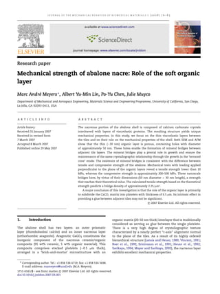
We assume that KIc = 1 MPa m1/2 , E = 100 GPa, and
that 2a = D, where D is the specimen diameter. Fig. 10a
shows the two curves given by Eqs. (7) and (8). They intersect
for a = 28 nm (D = 56 nm). This is indeed surprising,
and shows that specimens of this and lower diameter can
reach the theoretical strength. This is in agreement with
the experimental results: the holes in the organic layer
and asperities/bridge diameters are around 50 nm. Recent
analyses (Song et al., 2002, 2003; Gao et al., 2003) also arrive
at similar values.
It is possible to calculate the fraction of the tile surface
consisting of mineral bridges, f . Knowing that the tensile
Fig. 9 – Different models for sliding between tiles; intertile layer formed by (a) asperities; (b) organic layer acting as
viscoelastic glue; (c) mineral bridges.
9. 84
J O U R N A L O F T H E M E C H A N I C A L B E H AV I O R O F B I O M E D I C A L M AT E R I A L S
1 (2008) 76–85
is in agreement with the results by Schäffer et al. (1997) who
reported a hole density of 97/µm2 . This is consistent with the
present measuerments. One conclusion that can be drawn
is that a large number of asperities are indeed incomplete
bridges and that these bridges are a small but important
fraction of the protuberances.
4.
Conclusions
The observations made herein indicate that the organic layer,
while playing a pivotal role in the growth of the aragonite
crystals in the c direction (perpendicular to tile surface),
may have a minor role in the mechanical strength. The
tensile strength in the direction perpendicular to the layered
structure can be explained by the presence of the mineral
bridges. These bridges, having a diameter of approximately
50 nm, have a tensile strength no longer determined by
the critical crack size, but by the theoretical strength. Their
number is such that the tensile strength of the tiles (parallel
to the tile/shell surface plane) is optimized for the tile
thickness of 0.5 µm, as shown by Lin and Meyers (2005). A
higher number of bridges would result in tensile fracture of
the tiles with loss of the crack deflection mechanism. This is
a viable explanation for the small fraction of asperities that
are bridges.
It is concluded that the scale of the structural components
in nacre is an important parameter. Efforts at mimicking
these biological composites have to incorporate the scale to
derive the full benefit of these hierarchical designs (Mayer,
2005). Indeed, abalone is inspiring scientists in the synthesis
of novel materials as evidenced by a recent report (Deville
et al., 2006).
Fig. 10 – (a) Tensile strength of mineral as a function of
size; (b) calculated number of mineral bridges per tile as a
function of bridge diameter.
strength is σt and assuming that the bridges fail at σth , we
have
σt
f=
.
(9)
σth
The number of bridges per tile, n, can be calculated from
f=
nAB
AT
(10)
where AB is the cross-sectional area of each bridge and AT is
the area of a tile. Thus
n=
σt AT
.
σth AB
Acknowledgements
We are immensely grateful to Evelyn York, SIO, and Ryan
Anderson, Calit2, for helping us with SEM. Mr E. Kisfaludy,
SIO, helped us with the feeding and welfare of the
abalone. This research is supported by the National Science
Foundation DMR Grant 0510138. We thank Drs Linnette
Madsen and Joseph Akkara for support and encouragement.
Dr Chris Orme, Lawrence Livermore National Laboratory,
graciously allowed us to use the AFM facilities and hosted us
during our visits. Discussions with Profs R.J. Asaro and J.M.
McKittrick are gratefully acknowledged.
REFERENCES
(11)
Assuming that the tiles have a diameter of 10 µm and that the
bridges have a diameter of 50 nm (the approximate observed
value), one obtains, for σt = 3 MPa (the value at F = 0.5 in
Fig. 6a) and σth = 3.3 GPa, n = 36. This corresponds to a bridge
density of 2.25/µm2 .
The number of asperities seen in Fig. 8 exceeds
considerably the values for bridges calculated herein. From
the image the estimated density is 60/µm2 . Song et al. (2001,
2002) had determined an average density of 105/µm2 , which
Baer, E., Hiltner, A., Morgan, R.J., 1992. Biological and synthetic
hierarchical composites. Phys. Today 45, 60–67.
Bao, G., Suresh, S., 2003. Cell and molecular mechanics of
biological materials. Nat. Mat. 2, 715–725.
Barthelat, F., Li, C.M., Comi, C., Espinosa, H.D., 2006. Mechanical
properties of nacre constituents and their impact on
mechanical performance. J. Mater. Res. 21, 1977–1986.
Belcher, A.M., Gooch, E.E., 2000. In: Bauerlein, E. (Ed.), Biomineralization: From Biology to Biotechnology and Medical Application. Wiley-Interscience, Germany, p. 221.
10. J O U R N A L O F T H E M E C H A N I C A L B E H AV I O R O F B I O M E D I C A L M AT E R I A L S
Belcher, A.M., Hansma, P.K., Stucky, G.D., Morse, D.E., 1998. First
steps in harnessing the potential of biomineralization as a
route to new high-performance composite materials. Acta
Mater. 46, 733–736.
Belcher, A.M., Wu, X.H., Christensen, R.J., Hansma, P.K., Stucky,
G.D., Morse, D.E., 1996. Control of crystal phase switching
and orientation by soluble mollusk shell proteins. Nature 381,
56–58.
Belcher, A.M., 1997. Spatial and temporal resolution of interfaces,
phase transitions and isolation of three families of proteins
in calcium carbonate based biocomposite materials. Ph.D.
Thesis. U. California, Santa Barbara.
Bruet, B.J.F., Qi, H.J., Boyce, M.C., Panas, R., Tai, K., Frick, L., Ortiz,
C., 2005. Nanoscale morphology and indentation of individual
nacre tablets from the gastropod mollusc Trochus niloticus. J.
Mater. Res. 20, 2400–2419.
Currey, J.D., 1977. Mechanical properties of mother of pearl in
tension. Proc. R. Soc. Lond. 196, 443–463.
Deville, S., Saiz, E., Nalla, R.K., Tomsia, A.P., 2006. Freezing as a
path to build complex composites. Science 311, 515–518.
Evans, A.G., Suo, Z., Wang, R.Z., Aksay, I.A., He, M.Y., Hutchinson,
J.W., 2001. Model for the robust mechanical behavior of nacre.
J. Mater. Res. 16, 2475–2484.
Fritz, M., Belcher, A.M., Radmacher, M., Walters, D.A., Hansma, K.,
Stucky, G.D., Morse, D.E., 1994. Flat pearls from biofabrication
of organized composites on inorganic substrates. Nature 371,
49–51.
Fritz, M., Morse, D.E., 1998. The formation of highly organized
biogenic polymer/ceramic composite materials: The highperformance microaluminate of molluscan nacre. Col. Iner.
Sci. 3, 55–62.
Gao, H.J., Ji, B.H., Jäger, I.L., Arzt, E., Fratzl, P., 2003. Materials
become insensitive to flaws at nanoscale: Lessons from nature.
Proc. Natl. Acad. Sci. USA 100, 5597–5600.
Heuer, A.H., Fink, D.J., Laraia, V.J., Arias, J.L., Calvert, P.D., Kendall,
K., Messing, G.L., Blackwell, J., Rieke, P.C., Thomson, D.H.,
Wheeler, A.P., Veis, A., Caplan, A.I., 1992. Innovative materials
processing strategies: A biomimetic approach. Science 255,
1098–1105.
Jackson, A.P., Vincent, J.F.V., Turner, R.M., 1988. The mechanical
design of nacre. Proc. R. Soc. Lond. B 234, 415.
Ji, B.H., Gao, H.J., Hsia, K.J., 2004. How do slender mineral crystals
resist buckling in biological materials. Philos. Mag. Lett. 84,
631–641.
Ji, B.H., Gao, H.J., 2004. Mechanical properties of nanostructure of
biological materials. J. Mech. Phys. Solids 52, 1963–1990.
Laraia, J.V., Heuer, A.H., 1989. Novel composite microstructure and
mechanical behavior of mollusk shell. J. Am. Ceram. Soc. 72,
2177–2179.
Lin, A., Meyers, M.A., 2005. Growth and structure in abalone shell.
Mater. Sci. Eng. A 390, 27–41.
Lin, A.Y.M., Meyers, M.A., Vecchio, K.S., 2006. Mechanical
properties and structure of Strombus gigas, Tridacna gigas,
and Haliotis rufescens sea shells: A comparative study. Mater.
Sci. Eng. C 26, 1380–1389.
Mayer, G., Sarikaya, M., 2002. Rigid biological composite materials:
1 (2008) 76–85
85
Structural examples for biomimetic design. Exper. Mech. 42,
395–403.
Mayer, G., 2005. Rigid biological systems as models for synthetic
composites. Science 310, 1144–1147.
Menig, R., Meyers, M.H., Meyers, M.A., Vecchio, K.S., 2000. Quasistatic and dynamic mechanical response of Haliotis rufescens
(abalone) shells. Acta Mater. 48, 2383–2398.
Menig, R., Meyers, M.H., Meyers, M.A., Vecchio, K.S., 2001. Quasistatic and dynamic mechanical response of Strombus gigas
(conch) shells. Mater. Sci. Eng. A 297, 203–211.
Sarikaya, M., Aksay, J.A., 1992. Nacre of abalone shell; a natural
multifunctional nanolaminated ceramic-polymer composite
material. In: Case, S. (Ed.), Results and Problems in Cell
Differentiation in Biopolymers. Springer, Amsterdam, p. 1.
Sarikaya, M., Gunnison, K.E., Yasrebi, M., Aksay, J.A., 1990.
Mechanical property-microstructural relationships in abalone
shell. Mater. Res. Soc. 174, 109–116.
Sarikaya, M., 1994. An introduction to biomimetics: A structural
viewpoint. Microsc. Res. Tech. 27, 360–375.
Schäffer, T.E., Ionescu-Zanetti, C., Proksch, R., Fritz, M., Walters,
D.E., Almqvist, N., Zaremba, C.M., Belcher, A.M., Smith, B.L.,
Stucky, G.D., Morse, D.E., Hansma, P.K., 1997. Does abalone
nacre form by heteroepitaxial nucleation or by growth through
mineral bridges? 9, 1731–1740.
Shen, X.Y., Belcher, A.M., Hansma, P.K., Stucky, G.D., Morse, D.E.,
1997. Molecular cloning and characterization of lustrin A, a
matrix protein from shell and pearl nacre of Haliotis rufescens.
J. Biol. Chem. 272, 32472–32481.
Song, F., Soh, A.K., Bai, Y.L., 2003. Structural and mechanical
properties of the organic matrix layers of nacre. Biomater 24,
3623–3631.
Song, F., Zhang, X.H., Bai, Y.L., 2002. Microstructure and
characteristics in the organic matrix layers of nacre. J. Mater.
Res. 17, 1567–1570.
Srinivasan, A.V., Haritos, G.K., Hedberg, F.L., 1991. Biomimetics:
Advancing man-made materials through guidance from
nature. Appl. Mech. Rev. 44, 463–482.
Su, X.W., Belcher, A.M., Zaremba, C.M., Morse, D.E., Stucky, G.D.,
Heuer, A.H., 2002. Structural and microstructural characterization of the growth lines and prismatic microarchitecture in red
abalone shell and the microstructures of abalone “flat pearls”.
Chem. Mater. 14, 3106–3117.
Szilard, R., 2004. Theories and Applications of Plate Analysis. John
Wiley & Sons, New Jersey, p. 57.
Ugural, A.C., 1981. Stresses in Plates and Shells. McGraw-Hill, New
York, p. 27.
Vincent, J.F.V., 1991. Structural Biomaterials. Princeton University
Press, New Jersey.
Wang, R.Z., Suo, Z., Evans, A.G., Yao, N., Aksay, I.A., 2001.
Deformation mechanism in nacre. J. Mater. Res. 16, 2485–2493.
Weibull, W., 1951. A statistical distribution function of wide
applicability. J. Appl. Mech. 18, 293–297.
Zaremba, C.M., Belcher, A.M., Fritz, M., Li, Y., Mann, S., Hansma,
P.K., Morse, D.E., Speck, J.S., Stucky, G.D., 1996. Critical
transitions in the biofabrication of abalone shells and flat
pearls. Chem. Mater. 8, 679–690.