
Empfohlen
Weitere ähnliche Inhalte
Andere mochten auch
Andere mochten auch (13)
Solar charger
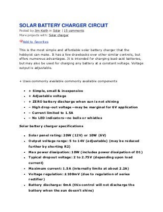
- 1. SOLAR BATTERY CHARGER CIRCUIT Posted by Jim Keith in Solar | 15 comments More projects with: Solar charger Add to favorites This is the most simple and affordable solar battery charger that the hobbyist can make. It has a few drawbacks over other similar controls, but offers numerous advantages. It is intended for charging lead-acid batteries, but may also be used for charging any battery at a constant voltage. Voltage output is adjustable. + Uses commonly available commonly available components + Simple, small & inexpensive + Adjustable voltage + ZERO battery discharge when sun is not shining – High drop-out voltage—may be marginal for 6V application – Current limited to 1.5A – No LED indicators—no bells or whistles Solar battery charger specifications Solar panel rating: 20W (12V) or 10W (6V) Output voltage range: 5 to 14V (adjustable) (may be reduced further by shorting R2) Max power dissipation: 10W (includes power dissipation of D1) Typical dropout voltage: 2 to 2.75V (depending upon load current) Maximum current: 1.5A (internally limits at about 2.2A) Voltage regulation: ±100mV (due to regulation of series rectifier) Battery discharge: 0mA (this control will not discharge the battery when the sun doesn’t shine)
- 2. Solar battery charger schematic 6V Applicaton Output Voltage: Set for 7V Input voltage: o Battery discharged (6V): 8.75V Min @ 1.5A (this is a little high for panels that are characterized for 6V applications) o Battery charged (7V): 9V Min @ 10mA (e.g.) 12V Application Output Voltage: Set for 14V Input voltage: o Battery discharged (12V): 14.75V Min @ 1.5A (Available from solar panel characterized for 12V operation) o Battery charged: (14V): 16V Min Minimum Head Voltage This is also referred to ―drop-out voltage.‖ The input voltage must exceed the output voltage by about 2.75V @ 1.5A. Fortunately, when
- 3. the battery discharged, the output voltage is lower so the solar panel voltage will also be lower. When fully charged, the battery voltage will be high, but the current is very low—at this point, the drop-out voltage reduces to about 2V and the open circuit solar panel voltage also comes into play. The schottky rectifier was selected to reduce this head voltage requirement—the voltage drop of the schottky is about 0.5V @ 1.5A or about half that of a typical silicon rectifier. More advanced controls have a much lower head voltage requirement and will function better under marginal conditions. Maximum Power Dissipation The power is limited by the thermal resistances of both the LM317T and the heat sink. To keep the junction temperature below the 125°C Max, the power must be limited to about 10W. If a smaller or less effective heat sink is used, the maximum power dissipation must be de-rated. Fortunately, the LM317 has internal temperature limiting so that if it gets too hot, it shuts down thus protecting itself from damage. Max power comes into effect when charging a 12V battery @ 1.5A: e.g. battery voltage = 12V, solar panel = 18V. P = (18V – 12V) * 1.5A = 9W. So thermally, it is carefully matched to the current rating. If a solar panel that is characterized for 12V is applied with a 6V battery, the maximum current must be reduced to about 0.7A: e.g. battery voltage = 6V, solar panel voltage = 18V. P = (18V – 6V) * 0.7A = 9.6W. In this case, the solar panel power may not exceed 10W. When charging, the heat sink normally runs warm. When beginning to ―top off‖ or completing the charge at maximum voltage, the heat sink runs hot. When fully charged, the heat sink runs cool. This heat is not exactly wasted power—it is excess power that is unneeded in the process of charging a battery. Current Limiting
- 4. Current limiting is provided by the solar panel—it is not a commonly understood fact that the solar panel tends to be a constant current device. For this reason, a solar panel can withstand a short circuit. Therefore, the control does not need current limiting. Float Charge of Lead-Acid Batteries This control charges the battery at a constant voltage and also maintains a charged battery (float charge). The float charge voltage specification is a little lower, so to accommodate both charge and float charge voltage, a compromise is reached by simply reducing the voltage slightly—that is how ALL automotive systems operate. To obtain maximum charge in a 12V battery, set the control to 14.6V. Automotive systems further reduce voltage to 13 to 13.5V in order to accommodate high temperature operation as the battery is usually located in the hot engine compartment—battery has a negative thermal coefficient of voltage.
- 5. Application with other types of batteries It is difficult to determine how to set the voltage in this case. The easiest way to do this is to charge the battery fully using other means and then transfer the charged battery to the control and connect an ammeter in series. Increase the voltage setting until there is significant current and then back off the potentiometer until the current drops to perhaps 10mA or so. Some types of batteries such as lithium ion types must be disconnected after charging to prevent degradation. Solar Battery Charger Protection C1 provides substantial protection against static discharge. There is no protection against reverse polarity or mis-wiring. It is protected if solar panel is connected reverse without battery connected, or if battery is connected reverse without solar panel connected. However, if the battery or solar panel is misconnected simultaneously, who knows? anyone care to experime