Incoming and Outgoing Shipments in 3 STEPS Using Odoo 17
Manuale Sparrowhawk XXT / XXB
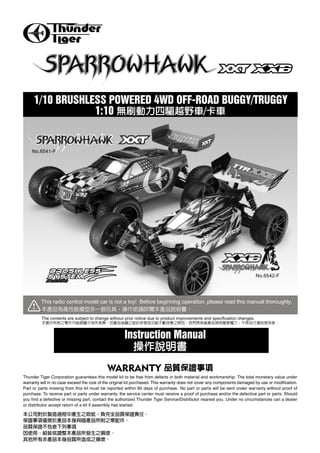
1. 1/10 BRUSHLESS POWERED 4WD OFF-ROAD BUGGY/TRUGGY
1:10 /
No.6541-F
No.6542-F
This radio control model car is not a toy! Before beginning operation, please read this manual thoroughly.
The contents are subject to change without prior notice due to product improvements and specification changes.
Instruction Manual
WARRANTY
Thunder Tiger Corporation guarantees this model kit to be free from defects in both material and workmanship. The total monetary value under
warranty will in no case exceed the cost of the original kit purchased. This warranty does not cover any components damaged by use or modification.
Part or parts missing from this kit must be reported within 60 days of purchase. No part or parts will be sent under warranty without proof of
purchase. To receive part or parts under warranty, the service center must receive a proof of purchase and/or the defective part or parts. Should
you find a defective or missing part, contact the authorized Thunder Tiger Service/Distributor nearest you. Under no circumstances can a dealer
or distributor accept return of a kit if assembly has started.
2. INTRODUCTION
Thank you for your purchase of this Thunder Tiger product. You should enjoy many hours of fun and excitement from this advanced
R/C model. Thunder Tiger strives to bring you the highest level of quality and service we can provide. We race and test our cars around
the world to bring you state-of-the-art products.
We offer on-line help on our www.thundertiger.com forum and our product specialists are ready to take your call if you have any technical
questions. Please read all instructions and familiarize yourself with the systems and controls of this model before running. Have fun
and enjoy the exciting world of R/C!
24 www.thundertiger.com
CAUTION
Thanks you for purchasing a Thunder Tiger product. Please read all instructions thoroughly before operation.
1. This product is not a toy. It is a high performance model product. It is important to familiarize yourself with the model, its manual,
and its construction before assembly or operation. Children's operating under the supervision of an adult is necessary.
2. Always keep this instruction manual ready at hand for your assembling and operating reference, even after completing the assembly.
3. Do not operate model products in rain, on public roads, near crowds, near airport, or near areas with restricted radio operation.
4. This product, its parts, and its construction tools can be harmful to your health. Always exercise extreme caution when assembling
and/or operating this product. Do not touch any part of model that rotates.
5. Check your radio frequency with the proper operating frequency of the area or country. Always check if there are any modelers
operating on the same frequency as you are. Also, check your radio for proper operation before operating a model.
6. Use an adequate charger for the batteries and follow the instruction correctly.
7. Right after use, do not touch equipment on the model because they may generate high temperatures!
8. Do not stall the motor. The ESC may fail if power is applied to the motor when car cannot move freely.
9. By the act of assembling or operating this product, the user accepts all resulting liability. If the buyer is not prepared to accept this
liability, then he/she should return this product in new, unassembled, and unused condition to the place of purchase.
WARNING: To avoid a possible fire hazard, ALWAYS unplug the battery after use. Do NOT leave your vehicle unattended with
the battery plugged in.
1.
2.
3.
4.
5.
6.
7.
8.
9.
INDEX
INTRODUCTION 1 OPERATING RADIO STEERING FUNCTION 8
CAUTION 1 ADJUSTING THE ELECTRONIC SPEED CONTROL(ESC) 8
ITEMS REQUIRED FOR OPERATION 2 BLC-40C ESC SETUP PROGRAMMING 9
CHARGING THE BATTERY PACK 3 DRIVING BASIC 10
PREPARING THE CHASSIS 4 SHOCK ADJUSTMENT 10
RADIO BATTERY INSTALLATION 4 WHEEL AND TIRE PREPARATION 10
THE ACE RC COUGAR PS3I RADIO AND BLC-40C BRUSHLESS MAINTENANCE AFTER RUNNING 10
POWER SYSTEM 2.4GHz 5 DRIVING TIPS 11
RADIO OPERATION 7 TROUBLESHOOTING 12
BINDING PROCESS 7 SET UP 13
3. ITEMS REQUIRED FOR OPERATION
RTR CONTENTS
ACE RC Cougar PS3i Hex Wrench Set, 1.5mm / 2.0mm / 2.5mm / 3.0mm
3-Channel digital 2.4G pistol radio system , 1.5mm / 2.0mm / 2.5mm / 3.0mm
with Standard Servo.
3
4-Way Wrench ACE R/C BLC-40C speed control RIPPER IBL36/33-540C (SPARROWHAWK XXT)
4 40A RIPPER IBL36/39-540C (SPARROWHAWK XXB)
EQUIPMENT NEEDED
Not included in the kit
AA Alkaline dry batteries BLC ESC Setting Card 7.2V Compatible Power Charger 7.2V Battery Pack
(AC/DC Charger)
8 pieces for transmitter 7.2V
7.2V
2937 IB Ni-MH Batter Pack, 7.2V/IB2400
AT6116 US PLUG 2941 IB Ni-MH Batter Pack, 7.2V/IB3600
AT6117 EU PLUG
AT6118 UK PLUG
TOOLS NEEDED
M3 M2
Philips Screwdriver
4. 1 1.1 CHARGING THE BATTERY PACK
(Battery and Charger are not included in the kit. )
a. Once the battery ready to be charged, first plug the AC quick charger into the outlet of AC power source, and then connect the
battery input/output harness to the charger.
b. Continued to monitor the battery as it is being charged. As soon as the battery is fully charged, disconnect the battery. from the
charger plug (Over-charging or charging incorrectly using inadequate chargers may cause the battery pack to become dangerously
hot).
c. Make sure that the battery pack is completely discharged prior to charging. Discharging the battery pack by running the electric
motor until it slows down or using a discharger (Not included).
d. For best results, let the battery pack cool before charging. Heat may prevent the battery pack from charging to full capacity and
also decreases the performance of the battery.
a.
b.
45
c.
d.
1
PLUG INTO AC OUTLET.
3
AFTER CHARGE TIME EXPIRES,
AC
DISCONNECT
BATTERY PLUG FROM CHARGER PLUG.
2
CONNECT BATTERY PLUG
TO DC OUTLET PLUG FROM CHARGER.
1.2 LiPo BATTERIES
Lithium Polymer (LiPo) batteries are becoming popular for use in R/C models due to their compact size, high energy density, and
high-current output. However, these types of batteries require special care and handling procedures for long life and safe operation.
Warning: Lithium Polymer (LiPo) batteries are intended only for advanced users that are educated on the risks associated
with LiPo battery use. THUNDER TIGER/ACE RC does not recommend that anyone under the age of 16 use or
handle LiPo battery packs without the supervision of a knowledgeable and responsible adult.
Important: Do not use NiCd/NiMH battery chargers for LiPO batteries. If you do not use a special charger for LiPO batteries,
they will be damaged.
THUNDER TIGER/ACE
RC 16
The ACE RC BLC electronic speed control is able to use LiPo batteries with nominal voltage not to exceed11.1 volts (3S packs).
Exceeding these voltages may result in damage to your brushless system. LiPo batteries have a minimum safe discharge voltage
threshold that should either not be exceeded. The ACE RC BLC electronic speed control is equipped with built-in Low-voltage detection
that cuts the power automatically when batteries have reached their minimum voltage (discharge) threshold. Refer to the low power
auto-cut table in the ESC instruction manual. It is the driver’s responsibility to stop immediately to prevent the battery pack from being
discharged below its safe minimum threshold. It is critical for you, the user, to follow all other instructions supplied by the battery
manufacturer and the charger manufacturer for proper charging, use, and storage of LiPo batteries. Make sure you understand how
to use your LiPo batteries. Be aware that THUNDER TIGER/ACE RC shall not be liable for any special, indirect, incidental, or
consequential damages arising out of the installation and/or use of LiPo
batteries in THUNDER TIGER models.
ACE RC BLC 11.1 volts (3S packs)
ACE RC BLC
THUNDER TIGER/ACE RC
5. 2 PREPARING THE CHASSIS
a b c
a. Remove the body pins (2 pcs.) and detach the body.
b. Straighten antenna and insert into antenna tube.
c. Put the antenna wire through the antenna pipe. (Do not cut or shorten antenna wire.!) Push the antenna pipe into the chassis
mount hole.
a. 2
b.
c.
3 INSTALLING RADIO & POWER SYSTEM BATTERIES
(Battery shown is not included in the kit )
a b
a. Install 8pcs alkaline or rechargeable AA-size batteries (Not Included) into transmitter.
b. Install the power pack and connect to the ESC.
Caution: Confirm wiring and connections before connecting thespeed control to the battery. Incorrect polarity will damage
your speed control.
a.
b. 7.2V R
6. 4 The ACE RC Cougar PS3i Radio and BLC-40C
Brushless Power System
2.4GHz
1
5
11
4
3
6
1 Transmitter Antenna
2
2 Power Indicator
10
3 Edit Buttons
4 LCD Display
14 5 Digital Steering Trim lever
12
6 Digital Throttle Trim lever
7 Digital Steering D/R(Dual Rate) lever
9 13
7 8 AUX Ch Button
9 External Charging Jack
10 2.4GHz TX RF Module and binding SW
8
11 Steering Wheel
12 Power Switch
13 Throttle Trigger
14 Steering Tension Adjustment
15 Battery Cover
15
4.1 ACE RC Cougar PS3i 2.4GHz
Battery
Connector (Male)
MOTOR
ON/OFF Cooling Fan
Switch Connector
(for optional use)
ESC
ANTENNA RECEIVER
To Receiver (CH2)
CH2
(CH2)
To Motor
(Red/Yellow/Black) Heat Sink
CH1
7.2V POWER BATTER PACK
SERVO
4.2 MODEL WIRING DIAGRAM
7. 1. Transmitter Antenna: Straighten up the antenna before operating the model.
2. Power Indicator: The LED light indicates power is "on" or "off".
3. Edit Buttons: The Left and Right buttons are the "functions" selecting keys. The up (+) and down (-) buttons are the keys for adjusting
values . Toggle between functions by pressing the "Edit Buttons" (left and right keys) and adjust settings with the up and down keys.
4. LCD Display: The Cougar transmitter features an "Easy-to-Read” LCD Display. Battery status, functions and settings are all clearly displayed
on the screen.
5. Digital Steering Trim lever: Push this lever left or right to adjust the center point on the steering servo. A cursor on the LCD screen’s top
ruler indicates current Steering Trim adjustments. Steering Trim adjustments ensure the model runs straight.
6. Digital Throttle Trim lever: Push this lever up or down to adjust the center point on the throttle/brake servo. A cursor on the LCD screen’s
left ruler indicates current Throttle Trim adjustments. Throttle Trim adjustments set the braking amount for "Drag Brake" and "Coast Brake".
NOTE: The Digital Throttle Trim function adjusts neutral point without affecting maximum throttle servo travel and full-throttle
position.
The Digital Steering Trim function adjusts maximum steering servo travel for both left and right steering. If adjustments are incorrect,
steering linkage binding or damages to the steering servo may occur.
7. Digital Steering D/R(Dual Rate) lever: Push this lever left or right to adjust the amount of steering dual rate. Right to increase dual rate,
left to decrease dual rate.
8. AUX Ch Button: Additional control function for the model.
9. External Charging Jack: For recharging the transmitter battery (only use a rechargeable NiCd/NiMH battery pack.)
10. 2.4GHz TX RF Module and binding SW: The Binding SW button is located on the 2.4GHz TX RF module unit.
11. Steering Wheel: Controls steering of the model.
12. Power Switch: Slide the switch to turn the transmitter on or off. The "DISPLAY" position provides direct access to the transmitter’s edit
buttons and trim levers without causing frequency interferences to other transmitters. Do not attempt to drive the model under the “DISPLAY”
mode.
13. Throttle Trigger: Pull or push to control speed and forward / backward motion.
14. Steering Tension Adjustment: Use a Phillip type screwdriver to tighten or loosen the tension of the steering wheel.
15. Battery Cover: Slide cover to install or remove batteries.
1.
2. LED
3.
4. LCD
5. LCD ST
6. LCD
7.
8.
9.
10. 2.4GHz 2.4GHz BINDING SW
11.
12.
13.
14.
15.
8. 5a
RADIO OPERATION
b c
OFF ON
a. When turning radio system on. Turn the transmitter on first, then turn on the ESC.
b. When turning the radio system off. Turn the ESC off first, then turn off the transmitter.
c. Reversing servos. Enter the NORM and REV mode by pressing the "up" and "down" keys.
Caution: Do not run the transmitter's battery flat or you will lose control of the car. For additional details, please refer to
the transmitter instruction manual.
a.
b.
c. LCD “up”(+)
“down”(-) “NOR” “REV”
6a
BINDING PROCESS
b c LED: RED
LED: GREEN FLASH Switch on Power
d LED: GREEN
A binding feature is included in the ACE RC Cougar 2.4GHz spread spectrum system to ensure the transmitter and receiver bind
properly and prevent interference from other controllers. With the Ready-To-Run package, full binding procedure has been completed
at the factory prior to shipping. To manually bind Tx/Rx, please proceed as per the following steps:
a. Press and hold the “Binding SW button on the back side of the transmitter while turning on the transmitter.
b. Release the “Binding SW* button after the green LED flashes indicating the transmitter is binding.
c. Press and hold the bind button on the receiver while turning on the receiver. Binding process will then start automatically.
d. Successful binding is confirmed by the blinking LED turning to constant on the transmitter. The LED on the receiver turns greens.
Once binding is complete, the system automatically connects.
Note: Binding prrocess may take 3~10 seconds to execute. If binding fails, the LED on the receiver will turn red. Please turn
off the power and repeat steps a~d.
ACE RC Cougar PS3i 3 2.4GHz
a. "Binding SW"
b. LED "Binding SW"
c. "Binding SW"
d. LED LED
3~10 LED a
~d
9. 7 OPERATING RADIO STEERING FUNCTION
a b c
a. Check the radio steering functions. With the radio transmitter and receiver on, turn the steering wheel to the left. The front tires/wheels
should turn left accordingly. If not, flip the steering servo reverse switch.
b. Return the steering wheel to neutral. The front tires/wheels should point straight forward. If not, use the steering trim lever to
correct it.
c. Turn the steering wheel to the right. The front tires/wheels should turn right accordingly.
a.
b.
c.
8 ADJUSTING THE ELECTRONIC SPEED CONTROL(ESC)
BATTERY
Battery Wire
ESC
Motor
Wires
MOTOR
Receiver Wire
RX
Calibrating your ESC and transmitter.
1. Install the ESC according to the diagram shown above. Switch on the transmitter first, and then switch on the ESC power.
2. Once the ESC is switched on, it will emit a series sound indicating the ESC is actuating. Adjust the throttle trim to get the best
neutral position. When neutral is set, another confirmation sound is emitted. If it fails to set up neutral, the confirmation sound will
not be heard. In such a case, re-do & re-check the system again starting from Step1 of these instructions. This ESC is applicable
to transmitters with either 50/50 or 70/30 throttle/brake movement range.
3. Confirm that the throttle forward direction coincides with the ESC forward direction. Lift the car off its wheels. Move the throttle
forward and watch the wheel’s rotation direction, then move the throttle backwards and see if the system brakes.
4. If the wheels’ movement coincides with the throttle input then the setting is correct. If the movement is opposite then switch off
the ESC, change the setting on the transmitter’s throttle reversing switch, and go back to Step 2.
5. Motor rotation direction - Slowly apply throttle to check if the motor is rotating in the correct direction.
To reverse the direction of the motor, switch any two of the motor wires. Note: Do not reverse the battery wire connections!
Reversing the battery polarity will permanently damage the ESC.
6. For the first trial run, start with a smaller gear motor for 2~3 minutes then monitor the temperatures of both the ESC & motor. If
both temperatures are similar to each other, they are at good match. The gear ratio can then be properly adjusted to the desired
optimum ratio depending on the type of car and track. However, it is very important to always keep both temperatures under 95
°C, when selecting a gear ratio. A higher gear ratio (larger pinion or smaller spur gear) will increase the system temperature.
Running the system at increased temperatures will cause demagnetization of the motor, resulting in a dramatic drop of motor
efficiency.
7. It is ok to replace a higher gear ratio or a higher KV motor if the temperature is kept under 80 °C but it should be done in accordance
to the instructions in Step 6. Start from a lower ratio then incrementally adjust higher. Battery selection is also an important
consideration. Changing to a higher voltage battery will require a lower KV motor and/or a lower gear ratio, unless the original
motor has a low enough KV rating to begin with. The ESC will be burn out if the motor and gear ratio does not match the input
voltage properly. See the example below showing how battery voltage affects power output.
Input 7.2V, internal resitance 0.18 --- 40A
(V/R=I 7.2/0.18=40A)
Input11.1V, internal resistance 0.18 --- 61.6A
(V/R=I 11.1/0.18=61.6A)
10. 1. ESC " " ESC " "
ESC
ESC
50% 50% 70% 30%
2.
ESC ESC
ESC
3. 2~3 ESC
ESC 95 100
4. ESC ESC 80
Kv
Kv
ESC
ESC
7.2V 0.18 40A
(I=V/R 7.2/0.18=40) =288W
11.1V 0.18 61.6A
(I=V/R 11.1/0.18=61.6)=684W
3.9V ESC
Kv
9 BLC-40C ESC SETUP PROGRAMMING
(ESC Setting Card is not included in the kit
Driving forward
With the car at rest, move the throttle full forward and the car will be in so-called “Hard Start”
)
mode with a very fast initial start without any delay on accelerating. The car will reach the
full speed from still in the shortest time. The motor perfectly responds to the signal of ESC SETTING CARD
acceleration instantly.
(User can use the ESC setting card to set the level of forward driving power, there are 4 modes to select from. Default has been
set in standard mode. For more information, please see the instruction of ESC setting card.)
Braking
The brakes will be actuated by reversing the throttle direction while driving forwards. Braking power is modulated by the amount
of throttle input in the brake/reverse direction. The maximum braking power can be adjusted using the transmitter EPA (depends
on the functions of the selected transmitter, for details please consult the instructions of your transmitter). The brake efficiency will
also be influenced depending on whether the reversing function is switched on. See section “Driving backwards”.
Driving backwards
Reverse is actuated by moving the throttle to the brake/reverse direction after the car has come to a stop. Reverse speed is modulated
by the amount of throttle input in the brake/reverse direction. While the car is still moving forward, the brakes will be actuated when
the throttle is moved in the brake/reverse direction. Reverse will not engage until the wheels have come to a stop.
(User can use the ESC setting card to set the level of driving power, there are 3 modes to select from. Default has been set in
standard mode. For more information, please see the instruction of ESC setting card.)
Over temperature protection
Motor will be intermittently turned off if the temperature reaches around 95°C. An optional cooling fan is recommended to increase
ESC ventilation.
CUT
4
3
ESC 95 ESC ESC
ESC
11. 10 DRIVING BASIC
Stop (Neutral) Brake Reverse Acceleration
11 SHOCK ADJUSTMENT
6mm 4mm 2mm 1mm
Hard Suspension Soft Suspension
Use the included shock clips to adjust for spring pre-load.
12 WHEEL AND TIRE PREPARATION
a b c
a. Remove wheel lock nut using the 4-way wrench and detach wheels.
b. Replace fresh tires and wheels if the original tires are worn out.
c. Tighten the wheel lock nut.
a.
b.
c.
13 MAINTENANCE AFTER RUNNING
a. Always turn off the radio system and disconnect the battery pack when the car is not in use.
b. Remove sand, mud, dirt, and any other elements before storing the car.
c. Never use chemicals or any solvents to clean the chassis as it may cause damage to the electronics components and plastic
parts. Use compressed air, soft paintbrush, or toothbrush to clean dust and dirt.
a.
b.
c.
12. 14 DRIVING TIPS
a. Hold your elbows in and keep the
a.
transmitter antenna pointing straight
up.
b. Squeeze the throttle trigger or pull the
b.
throttle stick gently and steer the car
to left and right.
c. Squeeze the throttle trigger and
c.
release. Repeat this action to control
car speed.
d. If you are of unsure of the steering e. At first, set the steering D/R function f. Be careful not to squeeze the throttle
direction, practice with the transmitter for less steering response. trigger abruptly while steering.
facing towards you. e. D/R f.
d.
g. After you become used to the controls, experiment with high h. Practice doing figure 8S.
performance at full throttle and full steering. h. 8
g.