SlideShare a Scribd company logo
1 of 119
Download to read offline
Finland                  France                USA


          Finland                      Spain


               Working Group
                  B2-08
                    January 25, 2010
he first man to place a log across a stream was
probably criticized roundly by his fellow tribesmen for
defacing the countryside. Today we proudly show visitors our
bridges as scenic wonders-from the stately George Washington
in New York to the harp-stringed Golden Gate in San
Francisco. When transmission towers are given the same
purity of expression given great bridges, they, too, may be
acclaimed as Twentieth Century art form.

     Of course, there is a difference. We encounter bridges in a
personal way: we cross them. On the other hand, our contact
with transmission towers is remote. The only thing crossing
them is electricity. And so we are conditioned, psychologically,
to accept a bridge more easily than a power pole.

     The towers shown in this book are both simple and
functional in form. Particular care was given to fitting them
into their environment. Thus in preparing structures for urban
areas, we studied urban surroundings and expressed them in
the structures. We devoted similar attention to rural structures.

                                           All of us would
                                      prefer to place electric
                                      power underground or to
                                      transmit the power on an
                                      invisible beam. But until
                                      such techniques prove
                                      practical, we hope that
                                      the work shown here will
                                      serve     usefully    the
                                      dedicated designers and
                                      engineers who seek to
                                      preserve the integrity of
                                      our surroundings.


                                                Henry Dreyfuss
   “SOURCE” Elena Paroucheva
                                                 January 1968
Innovative Solutions for Overhead Line Supports

                                               Working Group
                                                  B2-08


TASK FORCE MEMBERS

Australia                           H. Hawes
Brazil                              J.B.G.F. da Silva (TF Leader)
Finland                             V. Numminen / T. Leskinen / K. Nieminen
France                              L. Pellet
Iceland                             E. Thorsteins
Norway                              G. Nesgard
Romania                             G. Gheorghita
Spain                               J. Fernández
United States                       L. Kempner

(*)Special Contributor              E. Paroucheva


Convener: J.B.G.F. da Silva (Brazil), Secretary: D. Hughes (United Kingdom), Regular members: A. Fuchs
(Germany), D.I. Lee (Korea), E. Thorsteins (Iceland), G. Nesgard (Norway), J.D. Serrano (R. South Africa), J. Fernandez
(Spain), J. Peralta (Portugal), J. Rogier (Belgium), L. Binette (Canada), L. Kempner (United States), L. Pellet (France),
N. Masaoka (Japan), R.C. Ramos de Menezes (Brazil), R. Jansson (Sweden), S. Villa (Italy), V. Numminen (Finland),
Corresponding members: C.G. Alamo (Venezuela), C. Laub (Czech Republic), C. Thorn (UK), F. Legeron (Canada),
F. Meza (Bolivia), G. Brown (Australia), G. Gheorghita (Romania), H Hawes (Australia), I. Magdi (Canada),
J.Molé(Cuba), J. Prieto (Spain), J. Toth (Canada), K. Nieminen (Finland), K. Van Dam (Belgium), M. Vanner (UK), R.
Guimarães (Brazil), T R. Peixoto (Brazil), Leskinen (Finland).


Copyright © 2007
“Ownership of a CIGRE publication, whether in paper form or on electronic support only infers right of use for personal purposes.
Are prohibited, except if explicitly agreed by CIGRE, total or partial reproduction of the publication for use other than personal and
transfer to a third party; hence circulation on any intranet or other company network is forbidden”.
Disclaimer notice
“CIGRE gives no warranty or assurance about the contents of this publication, nor does it accept any responsibility, as to the
accuracy or exhaustiveness of the information. All implied warranties and conditions are excluded to the maximum extent permitted by
law”.
TABLE OF CONTENTS

1.      INTRODUCTION ............................................................................................................................. 7

2.      EVOLUTION ON THE SOLUTIONS ............................................................................................ 8
     2.1 FIRST OHL TOWER AESTHETIC STUDIES ......................................................................................... 8
     2.2 CIGRÉ STUDIES ................................................................................................................................ 9
     2.3 FIRST INITIATIVES .......................................................................................................................... 11

3.      THE OVERHEAD LINE MONOPOLE SUPPORTS ................................................................. 12
     3.1 MAIN CHARACTERISTICS ............................................................................................................... 12
     3.2 STRUCTURAL CHARACTERISTICS ................................................................................................... 14

4.      THE CIGRE WGB2.08 STUDIES ................................................................................................. 15

5.      ADVANCED INNOVATIVE SOLUTIONS ................................................................................. 15
     5.1 SOLUTIONS FOR UNIQUE PLACES: THE FINNISH EXPERIENCE ......................................................... 15
     5.2 SOLUTIONS FOR SPECIFIC LINES ..................................................................................................... 19
        5.2.1 The Danish Experience .......................................................................................................................... 19
        5.2.2 The TL Salmisaari-Meilahti, Helsinki ................................................................................................... 22
     5.3 STANDARD AESTHETIC SOLUTIONS - THE FRENCH EXPERIENCE ................................................... 27

6.      OVERHEAD LINE TOWERS INTO ARTWORKS ................................................................... 29
     6.1 FINNISH SCULPTURES .................................................................................................................... 29
     6.2 FRENCH INITIATIVES ...................................................................................................................... 32
        6.2.1 Architect / Designers’ Tower Competition............................................................................................ 32
        6.2.2 Networks into Artworks ........................................................................................................................ 36
     6.3 ICELANDIC STUDIES ....................................................................................................................... 43

7.      ANALYSIS OF THE SOLUTIONS............................................................................................... 48

8.      CONCLUSIONS .............................................................................................................................. 55

9.      ACKNOWLEDGEMENTS ............................................................................................................ 55

10. REFERENCES ................................................................................................................................ 55

ANNEX A: WORLDWIDE OHL AESTHETIC SOLUTIONS......................................................... 57


                                                                                4
TABLE OF FIGURES
Figure 1 – H.Dreyfuss Pictorial Index ........................................................................................................ 8
Figure 2 -H.Dreyfuss Proposal ................................................................................................................... 9
Figure 3 - H.Dreyfuss Proposal .................................................................................................................. 9
Figure 4 – Architeture School Students’ Proposals .................................................................................. 11
Figure 5 – First Aesthetic Solutions ......................................................................................................... 11
Figure 6 – Monopole Solutions ................................................................................................................ 12
Figure 7 – Typical Pole Cross-Sections & Joints ..................................................................................... 12
Figure 8 – Typical PoleFoundation Details .............................................................................................. 13
Figure 9 - Pole deflections during Tests ................................................................................................... 14
Figure 10 – SCB2.08 Country Contributors ............................................................................................. 15
Figure 11 - 1994: ”Yellow beak” - Hiversalo, Turku. A. Nurmesniemi ................................................. 16
Figure 12 - 1995: "Blue Cranes", Espoo.Studio Nurmesniemi. ............................................................... 16
Figure 13 - 1995:Petäjävesi, Virkkala. B. Selenius .................................................................................. 17
Figure 14 - 1996: Tuusula. IVO Power Engineering. ............................................................................... 17
Figure 15 - 1998: Jyvaskylan, J. Valkama ............................................................................................... 17
Figure 16 - 2000: "Antinportti”, Hämeenlinna. Studio Nurmesniemi. ..................................................... 18
Figure 17 - 2000: Ilola, Porvoo................................................................................................................. 18
Figure 18 - 2001: Rekola, Vanta,. J. Valkama.......................................................................................... 18
Figure 19 - 2003: Oulu, Kuivasjarvi. ....................................................................................................... 18
Figure 20 - New 400kV line ..................................................................................................................... 19
Figure 21 - The Winning entry – Erik Bystrup......................................................................................... 19
Figure 22 - Transition from Donau- to design-towers .............................................................................. 19
Figure 23 - The lattice top ........................................................................................................................ 20
Figure 24 - Shafts in the landscape ........................................................................................................... 20
Figure 25 - Suspention V-string ............................................................................................................... 21
Figure 26 - Angle tower ............................................................................................................................ 21
Figure 28 - TL Salmisaari-Meilahti, Helsinki .......................................................................................... 22
Figure 27 – Prototype under test ............................................................................................................... 21
Figure 29 - First pencil drawings .............................................................................................................. 22
Figure 31 - A photo montage of the transmission line ............................................................................. 23
Figure 30 – Tower CAD drawings ........................................................................................................... 23
Figure 32 – Towers Manufacturing .......................................................................................................... 24
Figure 33 – Towers Finishing ................................................................................................................... 24
Figure 34 - Body parts Assembly ............................................................................................................. 25
Figure 35 – The Interesting Result ........................................................................................................... 25
Figure 36 – Tower Top Detail .................................................................................................................. 26
Figure 37 - The “ROSEAU” Tower – M. MIMRAM .............................................................................. 27
Figure 38 - The “FOUGERE” Tower - I. Ritchie, K. Gustafson.............................................................. 28
Figure 39 - The “ARVERNE” Tower - Transel, Linuhonnun.................................................................. 28
Figure 40 - Lempäälä.Konehuone / J. Valkama ....................................................................................... 29
Figure 41 – Nummela, Vihti. Konehuone/J. Valkama. ............................................................................ 30
Figure 42 - Vaasa, Palosaari. Konehuone/J. Valkama.............................................................................. 30
Figure 43 - Espoo, Suurpelto. Konehuone/J. Valkama. ........................................................................... 30
Figure 44 – “Antti’s Steps”, Helsinki. A. Nurmesniemi & J. Valkama ................................................. 31
Figure 45 - Eurajoki. Konehuone/J. Valkama. ......................................................................................... 31
Figure 46 - Well-Thought Reeds.Marc Mimram ...................................................................................... 32
Figure 47 - “f”s All The Way-Ritchie, RFR, Gustafson........................................................................... 33
Figure 48 - Slender Stabile. Deslaugiers, RFR,Gerpa Team .................................................................... 33
Figure 49 - “Ecosystem. Wilmotte, Technip, Petit-JeanTeam ................................................................. 34
Figure 50 - Card Game.Perrault, Ove Arup Team.................................................................................... 34
Figure 51 – Swan Neck.Euro RSCG Design,Tallon,Bet Jean Muller International Team ...................... 34

                                                                          5
Figure 52 - The Heron Aesthetics.Giugiaro Design Team ....................................................................... 35
Figure 53 – Haute Couture.Starck,Meda, Arsene-Henry and Triaud, de Miranda Team ......................... 35
Figure 54 - Art Installations on Overhead Line Supports......................................................................... 36
Figure 55 - Towers Sculptures .................................................................................................................. 36
Figure 56 - Sculptures- Electric Tower Models ....................................................................................... 37
Figure 57 - Sculptures- Cellular Antennas ............................................................................................... 37
Figure 58 - Amnéville-les-Thermes Location .......................................................................................... 38
Figure 59 – E. Paroucheva’s Studies ........................................................................................................ 38
Figure 60 - Erection of the artwork of ”Source” ...................................................................................... 39
Figure 61 - “Art Installations” Works on “Amnéville-Mortois OHL” ..................................................... 40
Figure 62 – Aesthetic Works on Amnéville-Mortois OHL .................................................................... 41
Figure 63 – “Source Lumière” – Pylon nº 10 ......................................................................................... 41
Figure 66 - “Source Flame” – Pylon nº 13 ............................................................................................. 42
Figure 64 - “Source Energy” – Pylon nº 12 ............................................................................................ 42
Figure 65 – “Source Water” – Pylon nº 11 .............................................................................................. 42
Figure 67 – “Walking Giants” –The Winner ............................................................................................ 44
Figure 68 – “Superstring” ......................................................................................................................... 45
Figure 69 – Landscape Tower Proposal ................................................................................................... 45
Figure 70 - Landscape Tower Proposal .................................................................................................... 46
Figure 71 - Landscape Tower Proposal .................................................................................................... 46
Figure 72 - Landscape Tower Proposal .................................................................................................... 47
Figure 73 - Landscape Tower Proposal .................................................................................................... 47
Figure 74 - Landscape Tower Proposal .................................................................................................... 48
Figure 75 – Tower Solutions for long OHL ............................................................................................ 49
Figure 76 - 1992 Seville Expo Tower - Spain ........................................................................................ 49
Figure 77 - Vaasa, Palosaari. Konehuone / J. Valkama........................................................................... 50
Figure 78 – Hameenlinna Landscape Tower .......................................................................................... 51
Figure 80 - The McDonald’s towers ........................................................................................................ 52
Figure 79 – The Mouse Head Tower ...................................................................................................... 52
Figure 81 – “Haute Couture pour Pylônes de Haute Tension” ................................................................. 53
Figure 83 – “Source Eau” – Pylône nº 11 ................................................................................................. 53
Figure 82 – “Towers and Arts” ................................................................................................................. 53
Figure 84 – The “Pagoda” Tower ............................................................................................................. 54
Figure 85 – The “Big Hat Towers”........................................................................................................... 54

                                                     ANNEX A - FIGURES
A1.     AUSTRALIA .................................................................................................................................. 59
A2.     BRAZIL .......................................................................................................................................... 62
A3.     CANADÁ ........................................................................................................................................ 67
A4.     DENMARK ..................................................................................................................................... 69
A5.     FINLAND ....................................................................................................................................... 71
A6.     FRANCE ......................................................................................................................................... 75
A7.     ICELAND ....................................................................................................................................... 75
A8.     ITALY ............................................................................................................................................. 88
A9.     JAPAN ............................................................................................................................................ 82
A10.    NORWAY ....................................................................................................................................... 95
A11.    ROMANIA ...................................................................................................................................... 96
A12.    SOUTH AFRICA .......................................................................................................................... 100
A13.    SPAIN ........................................................................................................................................... 101
A14.    SWEDEN ...................................................................................................................................... 106
A15.    SWITZERLAND .......................................................................................................................... 108
A16.    UNITED KINGDOM .................................................................................................................... 110
A17.    UNITED STATES ........................................................................................................................ 112
                                                                             6
1. INTRODUCTION

Years ago, aesthetics was not a value taken into account in the design of supports for new transmission
lines. Towers were not judged as “pretty” or “ugly”; they were just considered essential elements for
transmission of electricity. Many thousands of kilometers of transmission lines were, thus, built in all
continents, justified by the benefit of the electricity, considered a privilege of modern societies
organized in cities and factories with high consumption of energy.
This reality started to change mainly after the 60’s, when the environmental aspects of the lines and the
aesthetics of the supports, began to be more and more questioned in the implementation of new designs.
These changes can be understood as a result of many factors, such as:
   -   The existence of thousands of kilometers of lines already built in some countries and/or some
       regions.
   -   The evolution of the benefit of electricity, from “a privilege of few societies” to an “acquired
       right” of the citizens of the twentieth century. Electricity subtly became a “social right”, and an
       obligation of the governments to provide it.
   -   The increasing presence of transmission lines in inhabited areas, in such a way, that the towers
       became familiar elements in the cities.
   -   The difficulty of obtaining new urban corridors for bringing more power to central regions of
       cities especially those with high vertical growth.
   -   A greater environmental conscience motivated by the various aggressions to the environment in
       different regions of the world.


All this together made that the environmental aspects had become one of the most important premises in
the studies for the implementation of new transmission lines. Nowadays, transmission line projects have
to start with an environmental impact assessment, where environmental auditors identify and analyze the
impacts on the natural and human environment. New line routes have to find a balance between the need
of electricity transmission and the environmental perspectives. As part of these studies, the visual
appearance and the aesthetic of the towers began to play an important role in the analysis, once they are
the most visible elements on the landscape.
This Technical Brochure, through a research conducted by the Cigré WGB2.08, has the purpose of
reporting how these questions have been treated and solved recently around the world. It will also be
shown, how aesthetic towers have been used as solution to mitigate environmental impacts.


                                                    7
2. EVOLUTION ON THE SOLUTIONS
2.1   First OHL Tower Aesthetic Studies

The subject of the aesthetic of transmission line towers is not a new issue. During the 60’s, designers
and power lines engineers had already started to study improvements on their aesthetics.

One of the first remarkable initiatives was the studies reported by H. Dreyfuss & Associates, through a
publication of Edson Electric Institute in 1968 [1]. The document contains 47 innovative proposals for
Overhead Line Supports with different conductor configurations, with single or double circuits, and
using different materials such as steel, concrete or wood. Outstanding aesthetic solutions were
suggested, perhaps a little advanced for their time, but with a clear vision of the future (figures 1, 2 and
3).


                                   Figure 1 – H.Dreyfuss Pictorial Index


                                                     8
Figure 2 -H.Dreyfuss Proposal                 Figure 3 - H.Dreyfuss Proposal


The Dreyfuss’ studies were carried out in times when more and more power lines began to cohabitate
with citizens and cars on the cities, disputing their urban space. Transmission lines had to bring more
power to the downtown of big cities growing vertically, and/or cities expanding horizontally reaching
existing servitudes of lines already constructed. For these reasons, in different parts of the world,
Utilities have started to think more and more seriously on the aesthetic of the overhead line supports.


2.2   Cigré Studies

Due to the increasing environmental concerns regarding the impact of overhead lines, and consequently
the necessity of discussing solutions to mitigate them, the former Cigré SC22, in the beginning of the
80’s, created the Working Group 02 focusing on the environmental aspects of the lines. This group
finalized its works in 1986 publishing the Technical Brochure “The Environmental Impacts of High-
Voltage Overhead Transmission Lines”[2]. Many new ideas and suggestions were presented in that
Brochure, showing how it is possible to minimize impact of the overhead lines through creative
proposals for land occupation. Later on, in 1999, another Technical Brochure entitled High Voltage
Overhead Lines-Environmental Concerns, Procedures, Impacts and Mitigations (Technical Brochure nr.
147), was published by Cigré, enlarging the discussions about OHL routes and corridors, visual impact
and mitigation measures[3].

                                                  9
Motivated by the Cigré studies, in 1988, J. da Silva(Cigré former SC22 member) carried out an
interesting survey in the Architectural School of the Federal University of Minas Gerais, Brazil, on the
environmental aspects of the Overhead Lines. Forty students, splitted in eight small groups, were invited
to investigate the visual impact of the overhead transmission lines crossing the outskirts of the city of
Belo Horizonte, Brazil, with specific focus on the aesthetic of the towers. The unique demand to them
was the visual aspect, the aesthetic, the beauty of the towers, and/or their impact on the landscape. There
was no involvement on economy aspects, and no engagement with the necessity of energy
transportation.

Eight reports were produced revealing interesting perspectives from the vision of the common citizen,
and in this particular case, also from qualified citizens with an already acquired capability of making
critical analysis in terms of aesthetic. From this exercise, the following comments were considered
relevant, being interesting to be noted:


• “To be honest, we should assume that we have never paid attention to this matter before”.
• “In our cities, in general, there are many other constructions that have worse visual impact than the
   towers”.
• “From the architectural point of view, the transmission lines are characterized by the presence of
   the vertical element”.
• “Concerning the visual aspect of the transmission lines, all attention should be given to the towers.
   They should be treated as if they were sculptures”.
• “Looking a little bit closer and paying more attention, we could verify that there are beautiful and
   ugly towers”.
• “The towers cannot be ignored in the context: They should be camouflaged or exhibited”.
• “There are green and brown insulators. The green insulators are more beautiful”.
• “In special locations in the cities, the towers should be painted with live colors: lemon-green,
   shock-pink, blood-red, electric-yellow, etc.” (Figure 4)
• “Some towers could be used to decorate the cities like in Christmas Season by dressing them with
   chains of lights. Some others could also be used to support cable cars in parks and in other
   recreational areas”. (Figure 4).
• “The majority of the towers we found were latticed ones, but there are others from a more compact
   type.
• “From the aesthetical point of view, the most interesting tower we found was that from the compact
   type with box section like poles! They are slender, having an agreeable aspect and requiring a
   reduced base area to be settled”.
• “It is a pity, but we were informed that, as a general rule, the architects don’t participate in the
   transmission line projects”.
• “A sample of the population should be consulted about the preferable type of towers to be specified.
   We think that, if they were involved, they could accept more easily the existence of the transmission
   lines”.


                                                    10
Figure 4 – Architeture School Students’ Proposals

2.3   First Initiatives

The first practical initiatives in terms of “aesthetic towers” were not so ambitious and, basically,
oriented by the following principles:
    - To compact the lines and the supports as much as possible,
    - To reduce the number of structural elements on the towers,
    - To try to put them invisible or camouflaged in the landscape.

The compact solutions like the monopoles, the portal and V guyed, the chainette and the “cross-rope
suspension - CRS”, were solutions that have fulfilled with those objectives (Figure 5).
Thousands of kilometers of lines were constructed around the world using these solutions, which
aesthetic principles were based on simplicity, slenderness, symmetry, invisibility, reduced number of
structural elements, transparence.


        Monopole Support                     Portal Guyed                      Invisible Cross rope
            Brazil                             Sweden                               Argentina
                                  Figure 5 – First Aesthetic Solutions

                                                  11
3. THE OVERHEAD LINE MONOPOLE SUPPORTS

The most attractive solution for urban or suburban OHL towers has been the monopole supports. They
have been extensively used in all over the world, having adaptations and characteristics according to
local necessities.
There are many reasons for the extensive use of monopoles as the main aesthetic solution. Among them
it can be noteworthy: the simplicity, the slenderness, the low visual impact, the elegance, the beauty and
the reduced area for settlement. As a summary, they are attractive solutions having appropriate painting
system to fit them into special environmental circumstances (Figure 6).


           Monopole Support                   Aesthetic Pole           Compact Plus - Top insulated Support
               Brazil                             Japan                              Sweden


                                      Figure 6 – Monopole Solutions

3.1   Main Characteristics

Currently, the steel poles are made from carbon steel, mainly from high strength low alloy quality, being
shaped in modulus from 9 up to 12m length and with continuously variable polygon cross sections.
Depending on the dimensions involved (height and pole base width), the cross section used can be from
the square (or rectangular) to the dodecagonal or circular type (Figure 7). The most common joints used
are from the “overlapping splices” type, more suitable for suspension or light angle poles. The flanged
joints are currently used for the heavy angle or dead-end poles (Figure 7).


  SQUARE     HEXAGONAL    OCTAGONAL DODECAGONAL CIRCULAR


                                                                   Overlapping               Flanged

                              Figure 7 – Typical Pole Cross-Sections & Joints
                                                     12
The finishing types are specified basically to meet two needs: the corrosion protection and the aesthetic.
   For this purpose, the poles can be only externally painted with complete sealed joints, or hot-dip
   galvanized. The first solution provides an excellent aesthetic finishing, while the second one excellent
   protection. Therefore, some clients usually specify both finishing procedures, hot-dip galvanizing plus
   painting to obtain both advantages. For this, it is mandatory to use an appropriate “shop primer” over the
   galvanized coating in order to create a sufficient / necessary anchorage surface.

   As far as the pole foundations are concerned, they have been constructed using two different principles:
   the “direct embedment” or the “flanged base plate with anchor bolts”. The directly embedment on
   densed sand box, is a very economic solution mainly when designed for light suspension poles. The
   flanged base plate proposal is specially recommended for angle/dead-end poles, since the “two nuts
   adjustable system” helps to adjust the pole top deflection (Figure 8).


   Top seal
                                                        Nuts for adjusting


Densed sand


                                                       Anchor bolt
                                                        templates


      Sand box directly embedment type                                         Flanged base plate type


                                   Figure 8 – Typical PoleFoundation Details


                                                      13
3.2       Structural Characteristics

From the structural analysis point of view, it is important to observe that the monopoles are very flexible
structures with high level of elastic deformation (up to 5% of the height or even more) especially when
compared with similar latticed towers. For this reason, it is recommended that the calculations should be
carried out through “physical and geometric non linear” analysis. Second order effects, may be of great
relevance in the case of structural analysis for monopoles. To limit pole top deflection, however, can be
very expensive. For this reason, to reach both aesthetic and economic targets, it is suggested to verify
the pole top deformation at the following stages:

      -    At EDS condition: maximum top deformation equal or smaller than 1.5 to 2% of the pole height,
      -    At Ultimate Stage: 4 to 5% of the pole height.

 Figure 9 illustrates how deformable are the monopoles during the prototype tests.


                                    Figure 9 - Pole deflections during Tests


                                                      14
4. THE CIGRE WGB2.08 STUDIES

During the 90’s, the aesthetic of the OHL towers became a real issue in some regions, and the first
“landscape towers” were installed. New approaches and techniques were applied envisaging a better
public acceptance. Aiming to collect all those new ideas, the Cigré WGB2.08 created a new Task Force
entitled “Innovative Solutions for Overhead Line Supports”. The main objective of this new TF was to
collect all the initiatives around the world on aesthetic towers, and to produce a Brochure that could be a
reference book. Contributions were received from 17 countries: Australia, Brazil, Canada, Denmark,
Finland, France, Iceland, Italy, Japan, Norway, Romania, South Africa, Spain, Sweden, Switzerland,
United Kingdom and United States(Figure 10). All contributions were equally received as innovative
and aesthetics. An interesting databank was created showing the great variety of aesthetic solutions
adopted in different parts of the world. The solutions collected can be seen on the Annex A attached to
this Brochure.


              Australia                    Iceland                       Spain
              Brazil                       Italy                         Sweden
              Canada                       Japan                         Switzerland
              Denmark                      Norway                        United Kingdom
              Finland                      Romania                       United States
              France                       South Africa


                              Figure 10 – SCB2.08 Country Contributors


5. ADVANCED INNOVATIVE SOLUTIONS

Analyzing the solutions reported on the data bank, it could be identified that the so called “aesthetic
proposals” already adopted by the Utilities, follow three basic principles: to design aesthetic solutions
for unique places, for a single line, or standard aesthetic solutions. Examples of these trends can be
found, for example, in Finland, in Denmark and in France.

5.1   Solutions for unique places: The Finnish Experience

In Finland, there are good examples of unique tower solutions for specific places. The first landscape
towers were constructed in the early 90's by Fingrid Plc, the national grid operator in Finland. The
company wanted to get better public acceptance for the lines and, in some cases, to use them as
landmarks in public places. Fingrid hired for that purpose a well-known interior architect, Prof. Antti
Nurmesniemi to look at structures from a designer's point of view. The idea of Nurmesniemi was not to
hide the towers into the environment but, quite the opposite, to exhibit them. He wanted to show that
transmission line structures are not only functionally necessary objects but can also be visually attractive
and, in some cases, seen almost like pieces of art.

First landscape towers were installed in 1994, in the Southwest of Finland coast in the city of Turku. It
was a series of six towers, the design of which was matched with the gabled one-family houses of the
residential area nearby. Colour schemes were inspired by the surroundings (Figure 11).
                                                    15
Figure 11 - 1994: ”Yellow beak” - Hiversalo, Turku. A. Nurmesniemi

Few years later, a multi-level junction in Espoo was provided with a unique landmark and piece of
environmental art: a series of three 400 kilovolt towers, referred to as “Espoon sinikurjet” (Blue cranes
of Espoo) on account of their blue colour, (Figure 12).


                      Figure 12 - 1995: "Blue Cranes", Espoo.Studio Nurmesniemi.

After this, towers adapted to the surroundings were erected at the cities of Virkkala (Figure 13),
Tuusula(Figure 14), Jyvaskylan (Figure 15), Hameenlinna(Figure 16), Porvoo (Figure 17), Vantaa
(Figure 18) and Oulu(Figure 19) [4].


                                                   16
Figure 13 - 1995:Petäjävesi, Virkkala. B. Selenius   Figure 14 - 1996: Tuusula. IVO Power Engineering.


                                 Figure 15 - 1998: Jyvaskylan, J. Valkama


                                                     17
Figure 16 - 2000: "Antinportti”, Hämeenlinna.
                  "                                    Figure 17 - 2000: Ilola, Porvoo.
             Studio Nurmesniemi.                           Studio Nurmesniemi.


Figure 18 - 2001: Rekola Vanta,. J. Valkama.
                  Rekol
                  Rekola,        J                   Figure 19 - 2003: Oulu, Kuivasjarvi.


                                                18
5.2     Solutions for specific lines

The most common approach for reaching environmental friendly power lines, is to propose an aesthetic
solution for a specific line (or just a segment of the line) which crosses a sensitive region.
A good example of that, is the 400kV connection line between the cities of Aarhus and Aalborg in
Denmark. Another remarkable case is the transmission line Salmisaari-Meilahti in Helsinki, Finland.


5.2.1    The Danish Experience

According to [5], “Eltra is the system operator for the western part
of Denmark and owner of 400 kV grid. In March 2001, Eltra
received a license to construct a new 400 kV connection between the
cities of Aarhus and Aalborg, finalizing a major 400 kV ring (Figure
20).
This connection consists of overhead lines (117 km) with
intermediate sections of underground cables (14 km). A minor part of
the connection (27 km, shown on the map in green) is placed going
through a rural area with few technical installations. For this part
the Danish Minister for Energy decided to demand a new type of
tower based on a design competition.
                                                                            Figure 20 - New 400kV line

                                   The winning entry, selected from among 48 entries, was based on a
                                   tower with a cylindrical shaft of weathering steel and a tower top
                                   constructed as a lattice structure built of very few tubular members, all
                                   in stainless steel (Figure 21).


 Figure 21 - The Winning entry –
          Erik Bystrup
The overall design strategy for the new 400kV tower was to
design a tower which, unlike the existing Donau towers, did not
add visual “noise or interference” to the landscape. It is a tower
consisting of few elements and simplicity in the design. A tower
that would be read as aesthetic, calm, and repetitive elements
strolling through the landscape contours. (Figure 22).
To achieve this, a hierarchy on how a technical installation is
perceived in the landscape was developed:
 -At a distance, only the body of the poles is visible, standing
  quietly measuring out the landscape.
 -A little closer the insulators, the high voltage strings and the
  lattice top become visible.
-Close on the tower the details of the lattice top, the joints, the   Figure 22 - Transition from Donau- to
 connections and the electrical components become visible.                        design-towers

                                                      19
To support this hierarchy a choice of materials for
the different elements was suggested:
Weathering steel for the shaft and Stainless Steel
for the lattice top (Figure 23).


                                                                     Figure 23 - The lattice top


                                             Thus, in colour and texture the weathering steel becoming
                                             to the soil and the Stainless Steel lattice top becoming part
                                             of the sky.
                                             Together these materials would strengthen each other
                                             giving character to both elements and underline the design
                                             strategy.
                                             Due to local public opposition, the weathering steel for the
                                             shaft was abandoned and replaced with hot dip galvanized
                                             steel. (Figure 24).


    Figure 24 - Shafts in the landscape


The new 400 kV tower accomplishes a variety of assignments in one unique design:
- Creating a continuous visual appearance, thus,
- Minimizing the visual impact on the landscape.
- Angle tower capabilities allow a harmonious, ”bent” alignment of overhead line and landscape.
- Due to a straight-forward and inexpensive foundation method, the tower leaves a minimal footprint.
- Fitting lattice tubes with cast stainless steel joints allows faster in site assembling.
- The overall design allows a reduction of the magnetic fields.
One of the main adjustments of the winning entry was to change the vertical strings to V-strings in order
to be able to use the same tower as a suspension tower and as a running angle tower for minor angles,
to lower magnetic fields and to achieve a narrow right of way (Figure 25, 26).

The tower head is constructed as a lattice structure of stainless steel tubes welded together. The joints of
the tubes are casted in stainless steel. Developing the moulds for the castings and executing the castings
were difficult tasks due to the complicated geometry.


                                                    20
Figure 25 - Suspention V-string                   Figure 26 - Angle tower


A tower family with 3 types of supports was developed:
- Suspension tower
- Running angle tower for max. 5º deflection
- Angle tension tower for 5 to 45º line angle

A prototype of the suspension tower was constructed and
mechanically tested up to 105% of the maximum design
loads (Figure 27).


                                                            Figure 27 – Prototype under test


                                                 21
5.2.2   The TL Salmisaari-Meilahti, Helsinki

The towers for the transmission line between Salmisaari and Meilahti are located in the sea area in front
of the urban Helsinki district (Figure 28).


                               Figure 28 - TL Salmisaari-Meilahti, Helsinki

The line is 3.5 km long, and it includes nine new towers being 5 of them, the ones located on the sea
area, landscape towers designed by Prof. A. Nurmesniemi (Figures 29, 30, 31).

                          The TL Salmisaari-Meilahti, Helsinki


                                     Figure 29 - First pencil drawings
                                                    22
Figure 30 – Tower CAD drawings


                           Figure 31 - A photo montage of the transmission line

Due to the line's central location, it was the wish of the client, Helsinki Energy, to use these
environmentally amenable structures. Design and construction of foundations are generally very
difficult in offshore sites. In this line, two offshore towers were based on piled foundations. The longest
piles used had 21 m with 610 mm of diameter. The tension capacity was secured by drilling and
                                                    23
grouting the bar (length of 5 m) into the rock. After the concrete hardening, the tension capacities of the
piles were tested. The foundations themselves were made in the traditional way: with “pad and
chimney” and casting in dry circumstances. In order to keep the water away from the foundation works,
and to enable the underwater constructions, a steel coffer was used. A temporary bridge was constructed
for moving piling machine and the coffer to the place of the tower. Special attention was paid on the
positioning of the anchor bolts (16 pcs/tower leg). The profiles used on the fabrication of the landscape
towers were not of a standard type. Suitable manufacturing method had to be chosen. A half oval profile
was made from two pieces which were fabricated by using a trimming press. Half profiles were welded
together using a submerged arc welding against backing. The maximum length of tower parts was
designed not to exceed 12 m (Figure 32).


                                    Figure 32 – Towers Manufacturing

The erection of the towers had to be designed in such a way that the weight of the single parts did not
become too heavy. All joints between body parts were bolted with flange connections. Special lifting
and guiding devices had to be designed in order to get two leg parts assembled together (Figures 33, 34).


                                      Figure 33 – Towers Finishing


                                                    24
Figure 34 - Body parts Assembly

Upper parts were lifted as single modules while an additional frame had to be designed so that the
members could be assembled to body parts (Figures 35, 36).


                                 Figure 35 – The Interesting Result


                                                25
Figure 36 – Tower Top Detail


            26
5.3   Standard Aesthetic Solutions - The French Experience

To develop “standard aesthetic tower solutions” is one of the approaches used by RTE, the French
Transmission Grid Operator, for the integration of Overhead Lines into the environment. Aiming to
reach this objective, RTE has promoted two experiences for development of innovative supports: the
architects and the tower manufacturers design competitions.

The first architects design competition was carried out in 1994 and had, as main target, to develop
standard aesthetic solutions for 400kV Overhead Line Towers, to be used when and where it would be
necessary. As per [6], the specifications were very limited without any restriction, for example, to the
selection of materials to be used or phase arrangements. The only exception was the attendance to the
electrical clearances. The objective of this first experience was to give, as much freedom as possible to
the creativity of the designer. In most of the cases, the proposals were made by architects in association
with technical engineers. At the end of the process, eight competitors were selected among 121
candidates and two winners appointed. The jury was composed by RTE representatives, as well as
members of the fields of architecture, design and environment. The competition process lead to the
definition of two standard aesthetic tower families: the “Roseau (reed)” and the “Fougère (fern)”.

The “Roseau”, designed by M. Mimram, is a slender structure, exploring the verticality of the support
element. An original technology was used based on open-work modules of casting material for the lower
part of the tower (Figure 37). Eleven Roseau type towers have been installed in France so far.


                   Photo montage                                     Real
                          Figure 37 - The “ROSEAU” Tower – M. MIMRAM

The “Fougère” type support was designed by I. Ritchie and K. Gustafson (RFR Architects), and consists
of a tube tower whose originality lies on the distribution of conductors in a horizontal position spread
over two independent structures in the shape of an “f”. In this solution the architects were looking for a
very pure form (Figure 38 ). Two Fougère towers have already been installed in France.


                                                   27
Photo montage                                              Real

                      Figure 38 - The “FOUGERE” Tower - I. Ritchie, K. Gustafson


The main advantage of this first RTE experience was the great innovation in shapes obtained. As
disadvantages, it can be appointed the difficulty to transform a concept into industrial product, the time
taken for development and tests, and the high costs involved. All these lead to limit the use of that
aesthetic towers to exceptional sites.

The second experience was proposed only among support manufacturers and performed along
2004/2005. Differently from the architects’ competition of ten years ago, in this case, the functional
specifications were more restrict. It were defined the position of the phases, the number of circuits
(single or double), the materials to be used and suggestions of silhouette. The main objective of this
      le
experience was to obtain a tower design on the basis of
technical solutions, thus, avoiding industrialization
difficulties. This way, the proposals were expected to come
from the industry, either OHL manufacturer or pylon
suppliers. The advantages of that procedure were basically the
use of tested/existing solutions, with little industrialization
difficulties, reduced development times and at reasonable
costs.

The main disadvantage, as compared with the architects’
competition, is that, the creativity is reduced and, as a
consequence, the innovation is much more limited, resulting
in shapes and formats more traditional. With this procedure, a
new wood support was developed for using in the 225kV
OHL of RTE named as “The Arverne”. The prototype tower
was a proposal from Transel - Linuhonnun team, and 78
pylones were installed in France in 2005 (Figure 39).
                                                                 Figure 39 - The “ARVERNE” Tower - Transel,
                                                                                                   Transel
                                                   28                             Linuhonnun
6.   OVERHEAD LINE TOWERS INTO ARTWORKS

The various experiences carried out in the world with aesthetic towers were, generally, very successful
in terms of public acceptance. Those initiatives motivated the Utilities that had lines in sensitive areas,
to expand the concepts and the use of “landscape towers”. Since the 90’s, slowly, the towers were
evolving from OHL Supports to “Urban Electrical Sculptures”, as envisaged by H. Dreyfuss’ Studies
and Da Silva’s architecture students Consultation, in 1968 and 1988 respectively (see items 3.1 and
3.2).


6.1 Finnish Sculptures

In Finland, according to [7], “the transmission line towers designed by Studio Nurmesniemi represent a
straightforward design approach. The towers have an important downright vital purpose as a part of
the electricity transmission system, and their design naturally stems from proper functionality. In large
objects, an aesthetic appearance often means eliminating details; this is also the case with these towers.
The towers adapted to their background scenery and to the built-up environment represent technical
aesthetics at its best.”
After the well succeeded first experiences, landscape towers have continued to be designed and
constructed. As examples, Figures 40, 41, 42, 43, 44 and 45, show new solutions in the cities of
Lempäälä, Vihti, Vaasa, Espoo, Helsinki, Eurajoki, that are really sophisticated sculptures used as
towers to support conductors [4].


                              Figure 40 - Lempäälä.Konehuone / J. Valkama

                                                    29
Figure 41 – Nummela, Vihti. Konehuone/J. Valkama.


Figure 42 - Vaasa, Palosaari. Konehuone/J. Valkama    Figure 43 - Espoo, Suurpelto. Konehuone/J. Valkama.
                                                                                    Konehuone/
                                                                                    Konehuone/J


                                                     30
Figure 44 – “Antti’s Steps”, Helsinki.
    A. Nurmesniemi & J. Valkama


Figure 45 - Eurajoki. Konehuone/J. Valkama.


                      31
6.2   French Initiatives

In France, to mitigate overhead line impacts, EDF/RTE has adopted the philosophy of “the best
integration into the environment at a reasonable cost”. Currently, such integration is achieved by means
of:
    - The best route selection for the line,
    - Aesthetic towers when necessary,
    - Specific paintings or artistic treatment of lattice towers.


6.2.1 Architect / Designers’ Tower Competition
For developing “aesthetic towers”, as seen in item 6.3, RTE has promoted architects/designers’
competitions. As per [6], from the first competition carried out in 1994, when as much freedom as
possible was given to the proponents, eight solutions were chosen as most innovative and aesthetics
among 121 proposals. The photomontage of them can be seen on figures 46, 47, 48, 49, 50, 51, 52, 53.


                             Figure 46 - Well-Thought Reeds.Marc Mimram
                                                  32
Figure 47 - “f”s All The Way-Ritchie, RFR, Gustafson


Figure 48 - Slender Stabile. Deslaugiers, RFR,Gerpa Team
                          33
Figure 49 - “Ecosystem. Wilmotte, Technip, Petit-JeanTeam


                 Figure 50 - Card Game.Perrault, Ove Arup Team


Figure 51 – Swan Neck.Euro RSCG Design,Tallon,Bet Jean Muller International Team
                                       34
Figure 52 - The Heron Aesthetics.Giugiaro Design Team


          Figure 53 – Haute Couture.Starck,Meda, Arsene-Henry and Triaud, de Miranda Team


Looking at these solutions chosen by the Selection Committee, it can be perceived that they are more
“sculptures” than towers and, not by a coincidence, at the end of the selection process, the two winners
(Figures 46 and 47) were exactly those more OHL Towers oriented. “Artworks” and
“Engineeringworks” were side by side on the definition of the “Standard Aesthetic Solutions” in
France.


                                                  35
6.2.2   Networks into Artworks

A new technique has been recently utilized by RTE for improving the aesthetic of the transmission
Lines: The artistic treatment of lattice towers by Elena Paroucheva.

The works of E. Paroucheva aim at emphasizing the above ground networks such as, energy
transmission and distribution, renewable energy windmills, cellular relay–antennas, lighting–highways,
stadiums, public spaces, etc. Instead of trying to hide the support elements of these facilities in the
landscape, she transforms them into “artworks”[9]. Generally, she applies two kinds of techniques:
“Art Installations” and “Sculptures”. The “Art Installations” solutions treat the transformation of
existing infrastructures elements or buildings in the environment. They are investigated according to
their reception areas and allow the modification of their visual aspect into artistic works (Figure 54).


                         Figure 54 - Art Installations on Overhead Line Supports


The “Sculptures” explore new forms of towers to be implanted in the landscape, in both urban and rural
areas (Figure 55).


                                     Figure 55 - Towers Sculptures


                                                   36
The sculptures use "symbolically" the same modules of metallic constructions for the conception of
“pylons – sculptures”, “antennas – sculptures”, “wind energy – sculptures” and “lighting –
sculptures”(Figures 56 and 57).


                            Figure 56 - Sculptures- Electric Tower Models


                              Figure 57 - Sculptures- Cellular Antennas


                                                 37
In the city of Amnéville les Thermes, France (figure 58), "SOURCE", the artwork of E. Paroucheva,
has transformed 1.3kms of an existing segment of line into a monumental piece of art[10].
At its inauguration in 1950, the 225 kV "Amnéville-Montois" line, crossed a former heap of steel in
Lorraine. Afterwards, a tourist and thermal centre has been developed around the line creating, thus, a
complaint from the population and the 5 million tourists that currently visit the city per year.


                             Figure 58 - Amnéville-les-Thermes Location

In 2003, an agreement was signed between RTE and the City of Amnéville-les-Thermes, for the
implementation of an artistic treatment of the line. Rather than burying the line and removing the
towers, the choice made was exactly the opposite, to highlight them in the landscape. The artist E.
Paroucheva was then contacted and her artwork "SOURCE" implemented, transforming the existing
transmission line and its 4 support towers in “dressed illuminated creatures” (Figure 59).


                                 Figure 59 – E. Paroucheva’s Studies


The technique has utilized guy wires and stay cables and tubes of stainless steel over the high-voltage
structures, comprising 3 km of steel cables, 2.71 km of stays, 525m of plastic canvas, 576m of stainless
steel tubes, 384 fixations and 40 floodlights controlled by satellite.


                                                  38
The 4 towers of the segment of line crossing the village, numbers 10, 11, 12 and 13 were nominated,
"Source - light", "Source – water”, "Source – energy” and "Source - flame" respectively.

The realization of the works has comprehended casting foundations, painting of the pylons, assembling
of the guy wires and the dressing of the towers up down to their feet. Each installation has been
highlighted by monochrome illumination on the ground, ordered by satellite to illuminate the work at
nightfall (Figure 60).


                             Figure 60 - Erection of the artwork of ”Source”


Figure 61 shows the four towers of the “Amnéville-Mortois OHL” before and after they were treated
by the works of “Art Installations”, while the figures 62, 63, 64, 65 and 66 exhibit the complete works
and the results.


                                                   39
Figure 61 - “Art Installations” Works on “Amnéville-Mortois OHL”

                               40
Figure 62 – Aesthetic Works on Amnéville-Mortois OHL


      Figure 63 – “Source Lumière” – Pylon nº 10
                         41
Figure 64 - “Source Energy” – Pylon nº 12                Figure 65 – “Source Water” – Pylon nº 11


                               Figure 66 - “Source Flame” – Pylon nº 13

                                                 42
6.3   Icelandic Studies


Another interesting initiative that results in outstanding proposals of “electrical sculptures” for OHL
Supports, was that carried out in Iceland by Landsnet. Again, this was done through a competition
among architect/artist and engineer/designer teams. According to [8], “the competitors’ goal was to
look for new types of towers, that would blend well into the environment and, thus, minimize the visual
impact that the line towers undeniably have. In addition, emphasis was placed on minimizing electrical
and magnetic fields. The Selection Committee has considered that, the majority of the proposals
received for the competition, have fully addressed these goals. In addition, the Selection Committee has
also found the competitors’ diverse approaches regarding the appearance and visual impact of the
transport structures especially interesting. The competitors have chosen to either, glorify the towers, or
blend them carefully into the landscape and urban areas. It is the Selection Committee’s view that both
approaches have their place, and the competitors have succeeded well in showing the diversity of
possibilities.

The competitors’ goal was to obtain new ideas on types and appearances of a tower or towers for 220
kV high-voltage lines. Landsnet emphasized that specific consideration should be given to the visual
impact of towers (or lines), and that the competitors make proposals on the appearance of towers that
would take this into account as much as possible, regarding towers or lines both near urban areas and
in unsettled regions.

It was left up to the competitors whether all the towers would have a new look, particular towers and
selected environments would have a new or altered look, or whether the appearance of known types of
towers would be altered, one way or another. In addition, it was left up to the competitors whether the
tower/towers were blended well into the landscape in rural and urban areas, or the tower/towers would
stand out at specific sites”.

The main goal of the competition was that an idea for a new type of tower/towers would emerge, an
idea on the overall appearance of line routes, and that a proposal would emerge on a tower/towers that
could be developed further with respect to environmental impact, the electromagnetic field, lifetime and
costs.”

A total amount of 98 proposals were received from different regions of the world. The eight winner
solutions (in real order) selected are shown in the figures 67, 68, 69, 70, 71, 72, 73 and 74, where it can
also be seen the Selection Committee’s arguments justifying their choice.


                                                    43
Figure 67 – “Walking Giants” –The Winner
                                                   S. Krehn
Comment: Extremely beautiful and living support structure. “The walking giant” takes its basic
structure from the human body without becoming particularly anthropomorphized. The beauty springs
from utility, but the artistic purpose is not far ahead. The proposal nevertheless suffers from limited
installation, which is entirely out of step with the precious content.
Technical opinion: A technically possible solution that needs further development regarding the
hanging of insulator suspensions and Guy wires.


                                                  44
Figure 68 – “Superstring”
                                             Yong-ho Shin
Comment: A very dynamic and innovative form of support structure and extremely exquisite connection
between crossbars and the main support structure. These towers are prominent structures with artistic
value. The artistic implementation could go well in demarcated areas.
Technical opinion: Technically doable


                                 Figure 69 – Landscape Tower Proposal
                                     Bystrup Archtects and Designers
Comment: An especially well implemented proposal. The proposal provides for the insulators being
utilized as part of the support structure. Such an arrangement would have a revolutionary impact on
the development of high-voltage line towers. Falls technically short regarding implementation of
insulators.
Technical opinion: For the tower to meet electrical requirements, the core must be made of insulating
material. Today it is not possible to manufacture a sufficiently strong core with respect to the strength
required for the stress that must be expected.
                                                   45
Figure 70 - Landscape Tower Proposal
                                              T. Leung
Comment: Simple, innovative and strong proposal. Offers extensive possibilities for emphasizing line
routes in selected locations.
Technical opinion: The insulation system is not realistic and must therefore be further developed as to
how power lines go through the tower and are not isolated from it. The support structure also requires
development.


                                 Figure 71 - Landscape Tower Proposal
                                       Hornsteinar arkitektar ehf
Comment: Very good presentation. Towers well formulated as a convincing line support structure. It
would fit well into the environment visually.
Technical opinion: Technically developed solution.


                                                  46
Figure 72 - Landscape Tower Proposal
                                              J. Winchester
Comment: Revolution, vision or science fiction? There is no possibility of orienting oneself to how
realistic this proposal is within the time we are given. The proposal is nevertheless admirable, and it is
clear that resolving energy and environmental affairs in an idealized oscillation was very much on the
author’s mind.


                                  Figure 73 - Landscape Tower Proposal
                                               T. Shine
Comment: An ingenious Idea as a reference to giants in folktales and robots in modern times.
Technical opinion: Technically possible. The support system requires more work.
                                                   47
Figure 74 - Landscape Tower Proposal
                                    Bystrup Archtects and Designers

Comment: Singularly simple but thoroughly thought-out proposal. Each tower would have a strong
artistic impact on viewers, not least at close quarters. The delicate design makes the towers nearly
invisible from a distance except perhaps on bright, sunny days when the steel glint.
Technical opinion: Technically possible.


7. ANALYSIS OF THE SOLUTIONS

Analyzing the aesthetic solutions collected, and the arguments justifying them, interesting aspects can
be reported. Firstly, it can be observed an increasing environmental concern in almost all new OHL
projects around the world. This is valid for short or long lines, and for both, urban and rural landscapes.
There are, however, different policies regarding the OHL Lines and the environment in different
regions or countries.
In the case of long lines, normally crossing rural areas, cost is an absolute relevant issue which targets
of economy cannot, currently, be reached with aesthetic towers. In these cases, premises for
environmental friendly supports are, as already mentioned before, the invisibility, the transparence,
slenderness, compaction, camouflaged structures, all together driven by cost reduction (Figure 75).


                                                    48
Figure 75 – Tower Solutions for long OHL


In urban areas (or even rural ones sometimes), aesthetic solutions have been more and more been used
in different parts of the world, aiming to reach public acceptance. As seen in chapter 6, to achieve this,
different policies have been implemented such as to design “unique landscape towers” for specific
places, sometimes for a line or a segment, and even to design “standard aesthetic solutions”(Figures
76,77).


                                                     Figure 76 - 1992 Seville Expo Tower - Spain


                                                   49
Figure 77 - Vaasa, Palosaari. Konehuone / J. Valkama

For the specific case of the so called “landscape towers”, according to the Finnish experiences, the
procedure for reaching desirable environmental needs can be summarized as follows:

- A visit to the site. Special attention is paid on nearby line structures, on space limits, on the place
  itself and on the height of a new tower. The area is photographed from different angles.
- First drafts are made by the architect. First pencil sketches, then CAD pictures
- A design meeting is arranged with the architect, requester and design engineer. The meeting is held in
a
  cooperative spirit.
- A collective decision for the both technically and aesthetically suitable solution for the
  environment is reached.
- Design meetings (4-5) are held at different stages of design.
- After dimensioning different manufacturing issues concerning the tower members had to be
  negotiated with the workshop. Necessary modifications to detail drawings are also made.
- Possible painting colour is defined as well as the need for illumination.

Analyzing carefully the solutions collected around the world, a curious aspect could be observed.
Aiming to have public acceptance or to create a familiar atmosphere among towers and people, some
solutions are designed envisaging to link them “symbolically” with “icons" of their societies like, for
instance, the architecture, the history, the culture, traditional symbols, etc.
As example of such observation, it can be highlighted the aesthetic tower installed in Hameenlinna,
Finland in 1999. The city of Hameenlinna, the oldest inland town in Finland, is also Professor Antti
Nurmesniemi’s (Finnish design legend 1927-2003) hometown. The geometry of the tower was based

                                                      50
on the city’s landmark, Hame Castle, which is one of Finland’s medieval royal castles. It is believed to
have been built at the end of the 13th century. Some similarities can be seen in the geometry of the


towers, e.g., two pitched roofs of the Hame Castle’s fortress tower which are reflected on the surface of
Lake Vanajavesi (Figure 78).


The upper part of the tower is painted with ultra marine blue, which links up the tower with the lake
and the surroundings.


                            Figure 78 – Hameenlinna Landscape Tower


The tower was named “Antti’s gate” after the designer A. Nurmesniemi’s death, and it can be seen
from the highway when arriving to the city from the South.


Other good examples of innovative tower solutions linked with “symbols” of the populations or
integrated with the surroundings, are the “Mouse Head Towers” constructed in the city of Orlando
(Figure 79 ) and those herein called “The McDonald’s towers” (Figure 80 ) ,both in USA.


                                                   51
Figure 79 – The Mouse Head Tower


                             Figure 80 - The McDonald’s towers


                                            52
As already shown in chapter 7, another excellent experience focusing on the same objective is the
“Haute Couture Pour Pylônes de Haute Tension” proposed by E. Paroucheva for the artistic decoration
of the 225 kV OHL crossing the city of Amnéville les Thermes in France. The towers were modeled
with illuminated dressing like “top models” for a fashion exhibition (Figure 81). “Towers and art”
sharing the same space (Figures 82 and 83)


                   Figure 81 – “Haute Couture pour Pylônes de Haute Tension”


            Figure 82 – “Towers and Arts”             Figure 83 – “Source Eau” – Pylône nº 11

                                                53
In line with these perceptions, in Japan, “Pagoda tower” [11] and [12], has been designed, while in
Mexico, “Big Hat Towers” are common solutions (Figures 84, 85)


                                   Figure 84 – The “Pagoda” Tower


                                  Figure 85 – The “Big Hat Towers”
There is no doubt, that people, conscious or unconsciously appreciate those solutions that lovely
remind them images on the landscape.
                                                   54
8. CONCLUSIONS

Demand for electricity has grown dramatically over the last three decades, and the need for electricity
will continue to grow. As a consequence, different regions of the world will face different challenges
concerning the environmental impacts to supply more power. As far as transmission lines are
concerned, some Utilities will have to construct long (up to 2500 kms) UHV overhead lines in the near
future. For such lines, as reported in item 3, the so called “aesthetic solutions” will still be designed
based on simplicity, invisibility, slenderness, compaction, all together driven by costs. On the other
hand, in other regions of the world, the construction of new lines arouses more environmental and
aesthetic concerns. With the growing demand, there will be more requests for alternative design
solutions i.e. for visually attractive landscape towers. In the majority of the cases, the desirable solution
is to hide the structures, putting them invisible or camouflaged. When, for any reason, this is not
feasible, for sure it is always possible to make them more aesthetic, more beautiful!


9. ACKNOWLEDGEMENTS
The group acknowledges the support received from Elena Paroucheva, Hugo Carvalho, Marta
Nascimento and Mauro H.B. da Costa.
The convener also thanks Bernard Dalle and Pekka Riisio, SCB2 official reviewers, for their work and
comments.


10. REFERENCES

[1] Electric Transmission Structures – A design Research Program”, Henry Dreyfuss & Associates,
Elecric Research Council, Edison Electric Institute Pub. No. 67-61, 1968.

[2] Cigré SC22 WG02 - “The Environmental Impacts of High-Voltage Overhead Transmission Lines”,
1986.

[3] Cigré SC22 WG14, Brochure 147 – “High Voltage Overhead Lines Environmental Concerns,
Procedures, Impacts and Mitigations”, 1999.

[4] Pettersson, M. – “Aesthetic in Power Systems” – Helsinki University of Technology, August 2008.

[5] Öbro, H. et al – “New Type of Tower for Overhead Lines”. Cigré Report B2-305, Paris Session
2004.

[6] EDF Brochure - International Competition - Very High-Tension Pylons - An Innovative Spark,
April 1995.

[7] Exhibition “Suuret Linja” – Exhibition on Technology in Everyday Infrastructure - Antti
Nurmesniemi’s 75th Anniversary Exhibition, Fingrid Oyj, Helsinki, January 2003 – Pamphlet.

[8] Selection Committee’s Report for Competition on High-Voltage Transmission Line Towers –
Landsnet, April 2008.

[9] Paroucheva, E. “Networks into Artworks” – Pamphlet, 2007.
                                                     55
[10] Paroucheva, E. “Source” – Des pylônes se métamorphosent en oeuvres d’Art” – Booklet, 2007.

[11] CIGRE SC22. Sendai Meeting - Colloquium Environmental Impact of OHL in Japan,1997.

[12] AG Ajikawa Corporation Catalogue: “Aesthetic Towers & Monopoles”.

[13] Cigré, Paris Session 2002, SC22 Proceedings.

[14] Clark, M. – “Innovative Overhead Line Tower Concepts for National Grid Transco”, Edinburgh
Symposium, Paper 17 - 2003.

[15] Thomas & Betts Utility Division Catalogue.

[16] Kauniskangas,M et al – Form and Colour in the Landscape, History of the Finnish Landscape
   Tower, Fingrid, 2009.


                                                    56
ANNEX A:
              WORLDWIDE OHL AESTHETIC SOLUTIONS


             Australia                   Iceland                      Spain

             Brazil                      Italy                        Sweden

             Canada                      Japan                        Switzerland

             Denmark                     Norway                       United Kingdom

             Finland                     Romania                      United States

             France                      South Africa


Note: The names of the authors of the projects are indicated when informed. Complementary
information such as, names, localization of the project, voltage of the lines, quantity of structures
installed, costs, etc., can eventually be obtained through the contributors which names can be found on
page 59.


                                                  57
WORLDWIDE OHL AESTHETIC SOLUTIONS


This annex contains the contributions received by WGB2.08 TF3.1 about innovative/ aesthetic OHL
solutions in response of an international Cigré call.

All contributions were equally received as innovatives and aesthetics. No judgment or comments were
made about their aesthetic whatsoever.

                                                  CONTRIBUTORS


       Australia:         Henry Hawes - hhawes@bigpond.com
                          Graham Brown - grbrown@odg.com.au

       Brazil             João BGF da Silva – jbgfsilva@damp.com.br
                          Ruy Menezes - ruyrm@engelineas.com.br

       Canada             Paul Mèyere - In memoriam
                          Luc Binette - Binette.Luc@hydro.qc.ca

       Denmark            Henning Øbro - henning.oebro@eltra.dk

       Finland            Veikko Numminen - veikko.numminen@eltelnetworks.com
                          Kai Nieminen - Kai.Nieminen@eltelnetworks.com
                          Tapio Leskinen - Tapio.Leskinen@eltelnetworks.com

       France             Laure Pellet - laure.pellet@edf.fr
                          Bruno Rassineux - bruno.rassineux@rte-france.com
                          Elena Paroucheva – contact@art-elena.com

       Iceland            Egil Thorsthein - egill.thorsteins@efla.is

       Italy              Stefano Villa - stefano.villa@sae-pl.com

       Japan              Toshinaga Okamura - to_okamu@tomoe-corporation.co.jp
                          Norio Masaoka. - n_masaok@tomoe-corporation.co.jp

       Norway             Geir Nesgard - gen@norconsult.no

       Romania            Georgel Gheorghita - GheorghitaG@roeng.ro

       South Africa       José Diez Serrano - josed@taprojects.co.za
                          Rob Stephen – stepherg@eskom.co.za

       Spain              Emilio Palazuelos - emilio.palazuelos@iberdrola.es
                          José Fernández - jfernandez@mafersl.com
                          Juan Prieto – juprieto@ree.es

       Sweden             Roger Jansson – roger.jansson@vattenfall.com
                          Ralf Hartings - ralf.hartings@se.abb.com

       Switzerland        Paul De Weck – In memoriam

       United Kingdom     David Hughes – DHughes@skm.co.nz
                          Michelle Clark - michelle.clark@uk.ngrid.com

       United States      Joe Pohlman - joepohlman@comcast.net
                          Leon Kempner – lkempnerjr@bpa.gov

                                                      58
A1. Australia


   59
60
61
A2. Brazil


  62
63
64
65
66
A3. Canadá


  67
68
A4. Denmark


         Erik Bystrup/ Eltra


   69
70
A5. Finland


                                              "Blue Cranes", Espoo.Studio Nurmesniemi.
”Yellow beak” - Hiversalo, Turku.
         A.Nurmesniemi


  Pertajaves, Virkkala. B. Selenius                     Jyvaskylan, J. Valkama
                                         71
”Antinportti”, Hämeenlinna. Studio Nurmesniemi.


              Oulu, Kuivasjarvi.
                      72
Nummela, Vihti. Konehuone/J. Valkama.             Lempäälä.Konehuone / J. Valkama


  Vaasa, Palosaari. Konehuone/J. Valkama   ”Antti’s Steps”,Helsinki. A. Nurmesniemi & J. Valkama

                                             73
Espoo, Suurpelto. Konehuone/J. Valkama.


                                          74
Eurajoki. Konehuone/J. Valkama.

             A6. France


   Well-Thought Reeds. Marc Mimram


“f”s All The Way-Ritchie. RFR, Gustafson

                  75
Note: Aesthetic solution studies carried out by EDF/RTE as reported in reference [6]


                    Slender Stabile. Deslaugiers RFR,Gerpa Team


                   “Ecosystem. Wilmotte, Technip, Petit-JeanTeam


                        Card Game.Perrault, Ove Arup Team
                                        76
Note: Aesthetic solution studies carried out by EDF/RTE as reported in reference [6]


      Swan-Neck.Euro RSCG Design,Tallon,Bet Jean Muller International Team


                    The Heron Aaesthetics.Giugiaro Design Team


      Haute-Couture.Starck,Meda, Arsene-Henry and Triaud, de Miranda Team

                                        77
Note: Aesthetic solution studies carried out by
  EDF/RTE as reported in reference [6]


  The “ROSEAU” Tower – M. MIMRAM                   The “ARVERNE” Tower - Transel, Linuhonnun


                                              78
The “FOUGERE” Tower - I. Ritchie, K. Gustafson


                      79
Source Lumière – E. Paroucheva


Source Flame – E. Paroucheva
              80
Source Energy - E. Paroucheva


                                     Source Water - E. Paroucheva

                                81
A7. Iceland


  82
83
84
85
Note: Aesthetic solution studies carried out by Landsnet as reported in reference [8].


                                         86
Note: Aesthetic solution studies carried out by Landsnet as reported in reference [8].
                                         87
A8. Italy


   88
89
Note: Aesthetic solution studies carried out by ENEL / TERNA spa as reported by R.Rendina in
                                          reference [13]


                                             90
A9. Japan


  91
92
93
94
A10.        Norway


       95
96
A11.        Romania


       97
98
99
A12. South Africa


    100
A13.         Spain


       101
102
103
104
105
A14.         Sweden


Note: The Compact Plus solution developed
by Svenska Kraftnät and others as reported
by Hartings according to reference [13].

                                              106
Note: The Compact Plus solution developed
      by Svenska Kraftnät and others as reported
      by Hartings according to reference [13].


107
A15.    Switzerland


       108
109
A16.           United Kingdom


                                         One pole


                                          V pole


                                            Lattice
Note: Aesthetic solution studies carried out by National Grid Transco as reported by M.Clark
                                 according to reference [14].
                                            110
Single Pole with Arms


                                         Windmill


                                     Double Pole with Arms
Note: Aesthetic solution studies carried out by National Grid TRANSCO as reported by M.Clark
                                   according to reference [14].


                                            111
A17. United States


     112
113
114
115
116
117
118
119

More Related Content

What's hot

SLD-LINE LENGTH-NAMEPLATE DETAILS OF 765/400/220KV EQUIPMENT DETAILS-TYPES OF...
SLD-LINE LENGTH-NAMEPLATE DETAILS OF 765/400/220KV EQUIPMENT DETAILS-TYPES OF...SLD-LINE LENGTH-NAMEPLATE DETAILS OF 765/400/220KV EQUIPMENT DETAILS-TYPES OF...
SLD-LINE LENGTH-NAMEPLATE DETAILS OF 765/400/220KV EQUIPMENT DETAILS-TYPES OF...Pavan choudhary
 
PPT ON 33/11KV SUBSTATION
PPT ON 33/11KV SUBSTATIONPPT ON 33/11KV SUBSTATION
PPT ON 33/11KV SUBSTATIONRavi Phadtare
 
Sag in overhead transmission line, sag calculation & string chart
Sag in overhead transmission line, sag   calculation & string chartSag in overhead transmission line, sag   calculation & string chart
Sag in overhead transmission line, sag calculation & string chartvishalgohel12195
 
Voltage Source Converter (VSC) HVDC for Power Transmission – Economic Aspects...
Voltage Source Converter (VSC) HVDC for Power Transmission – Economic Aspects...Voltage Source Converter (VSC) HVDC for Power Transmission – Economic Aspects...
Voltage Source Converter (VSC) HVDC for Power Transmission – Economic Aspects...Power System Operation
 
Operational description of 400kv switchyard NTPC Ramagundam RSTPS
Operational description of 400kv switchyard NTPC Ramagundam RSTPSOperational description of 400kv switchyard NTPC Ramagundam RSTPS
Operational description of 400kv switchyard NTPC Ramagundam RSTPSPradeep Avanigadda
 
Design of substation (with Transformer Design)
Design of substation (with Transformer Design) Design of substation (with Transformer Design)
Design of substation (with Transformer Design) SayanSarkar55
 
400kv sub-station-final-ppt-by-mohit
400kv sub-station-final-ppt-by-mohit400kv sub-station-final-ppt-by-mohit
400kv sub-station-final-ppt-by-mohitMohit Awasthi
 
SWITCHYARD EQUIPMENTS & PROTECTION SYSTEMS
SWITCHYARD EQUIPMENTS & PROTECTION SYSTEMSSWITCHYARD EQUIPMENTS & PROTECTION SYSTEMS
SWITCHYARD EQUIPMENTS & PROTECTION SYSTEMSPartha Parida
 
220 kv Sub-station Summer Training ppt
220 kv Sub-station Summer Training ppt220 kv Sub-station Summer Training ppt
220 kv Sub-station Summer Training pptShubham Patel
 
Electrical transmission line
Electrical transmission lineElectrical transmission line
Electrical transmission lineDhananjay Jha
 
Financial transmission rights
Financial transmission rightsFinancial transmission rights
Financial transmission rightsSpringer
 
132 33kv substation documentation
132 33kv substation documentation132 33kv substation documentation
132 33kv substation documentationRajashekar Gurrala
 
Electrical Design of Overhead Lines.ppt
Electrical Design of Overhead Lines.pptElectrical Design of Overhead Lines.ppt
Electrical Design of Overhead Lines.pptAkdDeshmukh
 
Summer internship at pgcil
Summer internship at pgcilSummer internship at pgcil
Summer internship at pgcilAnurag Savarn
 
Electric substation
Electric substation Electric substation
Electric substation ANNU KUMAR
 
Sample calculation-for-differential-relays
Sample calculation-for-differential-relaysSample calculation-for-differential-relays
Sample calculation-for-differential-relaysRoberto Costa
 

What's hot (20)

SLD-LINE LENGTH-NAMEPLATE DETAILS OF 765/400/220KV EQUIPMENT DETAILS-TYPES OF...
SLD-LINE LENGTH-NAMEPLATE DETAILS OF 765/400/220KV EQUIPMENT DETAILS-TYPES OF...SLD-LINE LENGTH-NAMEPLATE DETAILS OF 765/400/220KV EQUIPMENT DETAILS-TYPES OF...
SLD-LINE LENGTH-NAMEPLATE DETAILS OF 765/400/220KV EQUIPMENT DETAILS-TYPES OF...
 
PPT ON 33/11KV SUBSTATION
PPT ON 33/11KV SUBSTATIONPPT ON 33/11KV SUBSTATION
PPT ON 33/11KV SUBSTATION
 
Sag in overhead transmission line, sag calculation & string chart
Sag in overhead transmission line, sag   calculation & string chartSag in overhead transmission line, sag   calculation & string chart
Sag in overhead transmission line, sag calculation & string chart
 
132kV GSS ppt
132kV GSS ppt132kV GSS ppt
132kV GSS ppt
 
Voltage Source Converter (VSC) HVDC for Power Transmission – Economic Aspects...
Voltage Source Converter (VSC) HVDC for Power Transmission – Economic Aspects...Voltage Source Converter (VSC) HVDC for Power Transmission – Economic Aspects...
Voltage Source Converter (VSC) HVDC for Power Transmission – Economic Aspects...
 
Sag calculation
Sag calculationSag calculation
Sag calculation
 
Power system security and smart grid
Power system security  and  smart gridPower system security  and  smart grid
Power system security and smart grid
 
Operational description of 400kv switchyard NTPC Ramagundam RSTPS
Operational description of 400kv switchyard NTPC Ramagundam RSTPSOperational description of 400kv switchyard NTPC Ramagundam RSTPS
Operational description of 400kv switchyard NTPC Ramagundam RSTPS
 
Design of substation (with Transformer Design)
Design of substation (with Transformer Design) Design of substation (with Transformer Design)
Design of substation (with Transformer Design)
 
400kv sub-station-final-ppt-by-mohit
400kv sub-station-final-ppt-by-mohit400kv sub-station-final-ppt-by-mohit
400kv sub-station-final-ppt-by-mohit
 
SWITCHYARD EQUIPMENTS & PROTECTION SYSTEMS
SWITCHYARD EQUIPMENTS & PROTECTION SYSTEMSSWITCHYARD EQUIPMENTS & PROTECTION SYSTEMS
SWITCHYARD EQUIPMENTS & PROTECTION SYSTEMS
 
220 kv Sub-station Summer Training ppt
220 kv Sub-station Summer Training ppt220 kv Sub-station Summer Training ppt
220 kv Sub-station Summer Training ppt
 
Relay testing procedure
Relay testing procedure Relay testing procedure
Relay testing procedure
 
Electrical transmission line
Electrical transmission lineElectrical transmission line
Electrical transmission line
 
Financial transmission rights
Financial transmission rightsFinancial transmission rights
Financial transmission rights
 
132 33kv substation documentation
132 33kv substation documentation132 33kv substation documentation
132 33kv substation documentation
 
Electrical Design of Overhead Lines.ppt
Electrical Design of Overhead Lines.pptElectrical Design of Overhead Lines.ppt
Electrical Design of Overhead Lines.ppt
 
Summer internship at pgcil
Summer internship at pgcilSummer internship at pgcil
Summer internship at pgcil
 
Electric substation
Electric substation Electric substation
Electric substation
 
Sample calculation-for-differential-relays
Sample calculation-for-differential-relaysSample calculation-for-differential-relays
Sample calculation-for-differential-relays
 

Viewers also liked

Campaña Iberia - Jonathan Tessaro
Campaña Iberia - Jonathan TessaroCampaña Iberia - Jonathan Tessaro
Campaña Iberia - Jonathan TessaroJonathan Tessaro
 
Ludo Bar "El Placer del Perú en tu boca"
Ludo Bar "El Placer del Perú en tu boca"Ludo Bar "El Placer del Perú en tu boca"
Ludo Bar "El Placer del Perú en tu boca"JuanCarlos1924
 
Ece 2015 2do de secundaria Comprensión de Textos con solucionario
Ece 2015 2do de secundaria Comprensión de Textos con solucionarioEce 2015 2do de secundaria Comprensión de Textos con solucionario
Ece 2015 2do de secundaria Comprensión de Textos con solucionarioANDY TERÁN RODAS
 
Top Tele Marketing Techniques
Top Tele Marketing TechniquesTop Tele Marketing Techniques
Top Tele Marketing TechniquesSon Huynh
 
2012 mkt635 motivações e valores determinantes para o consumo de alimentos or...
2012 mkt635 motivações e valores determinantes para o consumo de alimentos or...2012 mkt635 motivações e valores determinantes para o consumo de alimentos or...
2012 mkt635 motivações e valores determinantes para o consumo de alimentos or...Ricardo Vernieri Alencar
 
Klimastatus2013 anton eliassen
Klimastatus2013 anton eliassenKlimastatus2013 anton eliassen
Klimastatus2013 anton eliassenvideometno
 
Full 1 setembre cm
Full 1  setembre cmFull 1  setembre cm
Full 1 setembre cmprimer1213
 
Panorama del comercio electrónico y tendencias de negocios transfronterizos e...
Panorama del comercio electrónico y tendencias de negocios transfronterizos e...Panorama del comercio electrónico y tendencias de negocios transfronterizos e...
Panorama del comercio electrónico y tendencias de negocios transfronterizos e...Adigital
 
Building Structure Project 2 calculation
Building Structure Project 2 calculationBuilding Structure Project 2 calculation
Building Structure Project 2 calculationDexter Ng
 
Lezione 2 UniBa Linguaggi e pratiche comunicative del web
Lezione 2 UniBa Linguaggi e pratiche comunicative del webLezione 2 UniBa Linguaggi e pratiche comunicative del web
Lezione 2 UniBa Linguaggi e pratiche comunicative del webPaolo Lattanzio
 
ENT202 69% and Falling: Lowering the TCO of Enterprise Apps - AWS re: Invent ...
ENT202 69% and Falling: Lowering the TCO of Enterprise Apps - AWS re: Invent ...ENT202 69% and Falling: Lowering the TCO of Enterprise Apps - AWS re: Invent ...
ENT202 69% and Falling: Lowering the TCO of Enterprise Apps - AWS re: Invent ...Amazon Web Services
 
Agenda culturală ARCH-I pe luna septembrie 2016
Agenda culturală ARCH-I pe luna septembrie 2016Agenda culturală ARCH-I pe luna septembrie 2016
Agenda culturală ARCH-I pe luna septembrie 2016CosminCH
 

Viewers also liked (20)

GTC
GTCGTC
GTC
 
Campaña Iberia - Jonathan Tessaro
Campaña Iberia - Jonathan TessaroCampaña Iberia - Jonathan Tessaro
Campaña Iberia - Jonathan Tessaro
 
Nelly wesley signatures
Nelly wesley signaturesNelly wesley signatures
Nelly wesley signatures
 
Red del Futuro
Red del FuturoRed del Futuro
Red del Futuro
 
Aspects LéGaux D
Aspects LéGaux DAspects LéGaux D
Aspects LéGaux D
 
Master Class: Serious Illness Cover Booster
Master Class: Serious Illness Cover BoosterMaster Class: Serious Illness Cover Booster
Master Class: Serious Illness Cover Booster
 
Tema3 atención cliente
Tema3   atención clienteTema3   atención cliente
Tema3 atención cliente
 
Osho rogers ok
Osho rogers okOsho rogers ok
Osho rogers ok
 
Ludo Bar "El Placer del Perú en tu boca"
Ludo Bar "El Placer del Perú en tu boca"Ludo Bar "El Placer del Perú en tu boca"
Ludo Bar "El Placer del Perú en tu boca"
 
Ece 2015 2do de secundaria Comprensión de Textos con solucionario
Ece 2015 2do de secundaria Comprensión de Textos con solucionarioEce 2015 2do de secundaria Comprensión de Textos con solucionario
Ece 2015 2do de secundaria Comprensión de Textos con solucionario
 
Top Tele Marketing Techniques
Top Tele Marketing TechniquesTop Tele Marketing Techniques
Top Tele Marketing Techniques
 
2012 mkt635 motivações e valores determinantes para o consumo de alimentos or...
2012 mkt635 motivações e valores determinantes para o consumo de alimentos or...2012 mkt635 motivações e valores determinantes para o consumo de alimentos or...
2012 mkt635 motivações e valores determinantes para o consumo de alimentos or...
 
Klimastatus2013 anton eliassen
Klimastatus2013 anton eliassenKlimastatus2013 anton eliassen
Klimastatus2013 anton eliassen
 
Full 1 setembre cm
Full 1  setembre cmFull 1  setembre cm
Full 1 setembre cm
 
Producció
ProduccióProducció
Producció
 
Panorama del comercio electrónico y tendencias de negocios transfronterizos e...
Panorama del comercio electrónico y tendencias de negocios transfronterizos e...Panorama del comercio electrónico y tendencias de negocios transfronterizos e...
Panorama del comercio electrónico y tendencias de negocios transfronterizos e...
 
Building Structure Project 2 calculation
Building Structure Project 2 calculationBuilding Structure Project 2 calculation
Building Structure Project 2 calculation
 
Lezione 2 UniBa Linguaggi e pratiche comunicative del web
Lezione 2 UniBa Linguaggi e pratiche comunicative del webLezione 2 UniBa Linguaggi e pratiche comunicative del web
Lezione 2 UniBa Linguaggi e pratiche comunicative del web
 
ENT202 69% and Falling: Lowering the TCO of Enterprise Apps - AWS re: Invent ...
ENT202 69% and Falling: Lowering the TCO of Enterprise Apps - AWS re: Invent ...ENT202 69% and Falling: Lowering the TCO of Enterprise Apps - AWS re: Invent ...
ENT202 69% and Falling: Lowering the TCO of Enterprise Apps - AWS re: Invent ...
 
Agenda culturală ARCH-I pe luna septembrie 2016
Agenda culturală ARCH-I pe luna septembrie 2016Agenda culturală ARCH-I pe luna septembrie 2016
Agenda culturală ARCH-I pe luna septembrie 2016
 

More from RTE

Les métiers de RTE
Les métiers de RTELes métiers de RTE
Les métiers de RTERTE
 
Bilan électrique RTE 2015 : une année marquée par de fortes variations de con...
Bilan électrique RTE 2015 : une année marquée par de fortes variations de con...Bilan électrique RTE 2015 : une année marquée par de fortes variations de con...
Bilan électrique RTE 2015 : une année marquée par de fortes variations de con...RTE
 
bilan électrique 2014 de nos régions
bilan électrique 2014 de nos régionsbilan électrique 2014 de nos régions
bilan électrique 2014 de nos régionsRTE
 
Combinaisonok
CombinaisonokCombinaisonok
CombinaisonokRTE
 
Combinaisonok
CombinaisonokCombinaisonok
CombinaisonokRTE
 
Evolution conso-region
Evolution conso-regionEvolution conso-region
Evolution conso-regionRTE
 
Rapport prod conso
Rapport prod consoRapport prod conso
Rapport prod consoRTE
 
Solaire
SolaireSolaire
SolaireRTE
 
Rapport prod conso
Rapport prod consoRapport prod conso
Rapport prod consoRTE
 
Evolution conso-region
Evolution conso-regionEvolution conso-region
Evolution conso-regionRTE
 
Eoliens
EoliensEoliens
EoliensRTE
 
Echanges regions
Echanges regionsEchanges regions
Echanges regionsRTE
 
Bioenergie
BioenergieBioenergie
BioenergieRTE
 
Consos annuelles regionales
Consos annuelles regionalesConsos annuelles regionales
Consos annuelles regionalesRTE
 
Synthese bilan électrique 2014
Synthese bilan électrique 2014Synthese bilan électrique 2014
Synthese bilan électrique 2014RTE
 
Panorama des énergies renouvelables au 1er semestre 2014
Panorama des énergies renouvelables au 1er semestre 2014Panorama des énergies renouvelables au 1er semestre 2014
Panorama des énergies renouvelables au 1er semestre 2014RTE
 
À la découverte du bilan électrique 2013 de nos régions
À la découverte du bilan électrique 2013 de nos régionsÀ la découverte du bilan électrique 2013 de nos régions
À la découverte du bilan électrique 2013 de nos régionsRTE
 
Eolien et solaire : faisons le point en images !
Eolien et solaire : faisons le point en images !Eolien et solaire : faisons le point en images !
Eolien et solaire : faisons le point en images !RTE
 
Présentation bilan électrique 2013 (23 janvier 2014)
Présentation bilan électrique 2013 (23 janvier 2014)Présentation bilan électrique 2013 (23 janvier 2014)
Présentation bilan électrique 2013 (23 janvier 2014)RTE
 
Les chiffres clés du bilan électrique 2013
Les chiffres clés du bilan électrique 2013Les chiffres clés du bilan électrique 2013
Les chiffres clés du bilan électrique 2013RTE
 

More from RTE (20)

Les métiers de RTE
Les métiers de RTELes métiers de RTE
Les métiers de RTE
 
Bilan électrique RTE 2015 : une année marquée par de fortes variations de con...
Bilan électrique RTE 2015 : une année marquée par de fortes variations de con...Bilan électrique RTE 2015 : une année marquée par de fortes variations de con...
Bilan électrique RTE 2015 : une année marquée par de fortes variations de con...
 
bilan électrique 2014 de nos régions
bilan électrique 2014 de nos régionsbilan électrique 2014 de nos régions
bilan électrique 2014 de nos régions
 
Combinaisonok
CombinaisonokCombinaisonok
Combinaisonok
 
Combinaisonok
CombinaisonokCombinaisonok
Combinaisonok
 
Evolution conso-region
Evolution conso-regionEvolution conso-region
Evolution conso-region
 
Rapport prod conso
Rapport prod consoRapport prod conso
Rapport prod conso
 
Solaire
SolaireSolaire
Solaire
 
Rapport prod conso
Rapport prod consoRapport prod conso
Rapport prod conso
 
Evolution conso-region
Evolution conso-regionEvolution conso-region
Evolution conso-region
 
Eoliens
EoliensEoliens
Eoliens
 
Echanges regions
Echanges regionsEchanges regions
Echanges regions
 
Bioenergie
BioenergieBioenergie
Bioenergie
 
Consos annuelles regionales
Consos annuelles regionalesConsos annuelles regionales
Consos annuelles regionales
 
Synthese bilan électrique 2014
Synthese bilan électrique 2014Synthese bilan électrique 2014
Synthese bilan électrique 2014
 
Panorama des énergies renouvelables au 1er semestre 2014
Panorama des énergies renouvelables au 1er semestre 2014Panorama des énergies renouvelables au 1er semestre 2014
Panorama des énergies renouvelables au 1er semestre 2014
 
À la découverte du bilan électrique 2013 de nos régions
À la découverte du bilan électrique 2013 de nos régionsÀ la découverte du bilan électrique 2013 de nos régions
À la découverte du bilan électrique 2013 de nos régions
 
Eolien et solaire : faisons le point en images !
Eolien et solaire : faisons le point en images !Eolien et solaire : faisons le point en images !
Eolien et solaire : faisons le point en images !
 
Présentation bilan électrique 2013 (23 janvier 2014)
Présentation bilan électrique 2013 (23 janvier 2014)Présentation bilan électrique 2013 (23 janvier 2014)
Présentation bilan électrique 2013 (23 janvier 2014)
 
Les chiffres clés du bilan électrique 2013
Les chiffres clés du bilan électrique 2013Les chiffres clés du bilan électrique 2013
Les chiffres clés du bilan électrique 2013
 

Recently uploaded

Pitch Deck Teardown: Geodesic.Life's $500k Pre-seed deck
Pitch Deck Teardown: Geodesic.Life's $500k Pre-seed deckPitch Deck Teardown: Geodesic.Life's $500k Pre-seed deck
Pitch Deck Teardown: Geodesic.Life's $500k Pre-seed deckHajeJanKamps
 
Call Us 📲8800102216📞 Call Girls In DLF City Gurgaon
Call Us 📲8800102216📞 Call Girls In DLF City GurgaonCall Us 📲8800102216📞 Call Girls In DLF City Gurgaon
Call Us 📲8800102216📞 Call Girls In DLF City Gurgaoncallgirls2057
 
Call Girls Miyapur 7001305949 all area service COD available Any Time
Call Girls Miyapur 7001305949 all area service COD available Any TimeCall Girls Miyapur 7001305949 all area service COD available Any Time
Call Girls Miyapur 7001305949 all area service COD available Any Timedelhimodelshub1
 
Contemporary Economic Issues Facing the Filipino Entrepreneur (1).pptx
Contemporary Economic Issues Facing the Filipino Entrepreneur (1).pptxContemporary Economic Issues Facing the Filipino Entrepreneur (1).pptx
Contemporary Economic Issues Facing the Filipino Entrepreneur (1).pptxMarkAnthonyAurellano
 
Innovation Conference 5th March 2024.pdf
Innovation Conference 5th March 2024.pdfInnovation Conference 5th March 2024.pdf
Innovation Conference 5th March 2024.pdfrichard876048
 
Keppel Ltd. 1Q 2024 Business Update Presentation Slides
Keppel Ltd. 1Q 2024 Business Update  Presentation SlidesKeppel Ltd. 1Q 2024 Business Update  Presentation Slides
Keppel Ltd. 1Q 2024 Business Update Presentation SlidesKeppelCorporation
 
FULL ENJOY Call girls in Paharganj Delhi | 8377087607
FULL ENJOY Call girls in Paharganj Delhi | 8377087607FULL ENJOY Call girls in Paharganj Delhi | 8377087607
FULL ENJOY Call girls in Paharganj Delhi | 8377087607dollysharma2066
 
Youth Involvement in an Innovative Coconut Value Chain by Mwalimu Menza
Youth Involvement in an Innovative Coconut Value Chain by Mwalimu MenzaYouth Involvement in an Innovative Coconut Value Chain by Mwalimu Menza
Youth Involvement in an Innovative Coconut Value Chain by Mwalimu Menzaictsugar
 
Case study on tata clothing brand zudio in detail
Case study on tata clothing brand zudio in detailCase study on tata clothing brand zudio in detail
Case study on tata clothing brand zudio in detailAriel592675
 
Call Girls In Radisson Blu Hotel New Delhi Paschim Vihar ❤️8860477959 Escorts...
Call Girls In Radisson Blu Hotel New Delhi Paschim Vihar ❤️8860477959 Escorts...Call Girls In Radisson Blu Hotel New Delhi Paschim Vihar ❤️8860477959 Escorts...
Call Girls In Radisson Blu Hotel New Delhi Paschim Vihar ❤️8860477959 Escorts...lizamodels9
 
Buy gmail accounts.pdf Buy Old Gmail Accounts
Buy gmail accounts.pdf Buy Old Gmail AccountsBuy gmail accounts.pdf Buy Old Gmail Accounts
Buy gmail accounts.pdf Buy Old Gmail AccountsBuy Verified Accounts
 
Call Girls In Connaught Place Delhi ❤️88604**77959_Russian 100% Genuine Escor...
Call Girls In Connaught Place Delhi ❤️88604**77959_Russian 100% Genuine Escor...Call Girls In Connaught Place Delhi ❤️88604**77959_Russian 100% Genuine Escor...
Call Girls In Connaught Place Delhi ❤️88604**77959_Russian 100% Genuine Escor...lizamodels9
 
Islamabad Escorts | Call 03070433345 | Escort Service in Islamabad
Islamabad Escorts | Call 03070433345 | Escort Service in IslamabadIslamabad Escorts | Call 03070433345 | Escort Service in Islamabad
Islamabad Escorts | Call 03070433345 | Escort Service in IslamabadAyesha Khan
 
8447779800, Low rate Call girls in Uttam Nagar Delhi NCR
8447779800, Low rate Call girls in Uttam Nagar Delhi NCR8447779800, Low rate Call girls in Uttam Nagar Delhi NCR
8447779800, Low rate Call girls in Uttam Nagar Delhi NCRashishs7044
 
Lowrate Call Girls In Sector 18 Noida ❤️8860477959 Escorts 100% Genuine Servi...
Lowrate Call Girls In Sector 18 Noida ❤️8860477959 Escorts 100% Genuine Servi...Lowrate Call Girls In Sector 18 Noida ❤️8860477959 Escorts 100% Genuine Servi...
Lowrate Call Girls In Sector 18 Noida ❤️8860477959 Escorts 100% Genuine Servi...lizamodels9
 
Organizational Structure Running A Successful Business
Organizational Structure Running A Successful BusinessOrganizational Structure Running A Successful Business
Organizational Structure Running A Successful BusinessSeta Wicaksana
 
Call Girls In Sikandarpur Gurgaon ❤️8860477959_Russian 100% Genuine Escorts I...
Call Girls In Sikandarpur Gurgaon ❤️8860477959_Russian 100% Genuine Escorts I...Call Girls In Sikandarpur Gurgaon ❤️8860477959_Russian 100% Genuine Escorts I...
Call Girls In Sikandarpur Gurgaon ❤️8860477959_Russian 100% Genuine Escorts I...lizamodels9
 
Market Sizes Sample Report - 2024 Edition
Market Sizes Sample Report - 2024 EditionMarket Sizes Sample Report - 2024 Edition
Market Sizes Sample Report - 2024 EditionMintel Group
 
Digital Transformation in the PLM domain - distrib.pdf
Digital Transformation in the PLM domain - distrib.pdfDigital Transformation in the PLM domain - distrib.pdf
Digital Transformation in the PLM domain - distrib.pdfJos Voskuil
 

Recently uploaded (20)

Pitch Deck Teardown: Geodesic.Life's $500k Pre-seed deck
Pitch Deck Teardown: Geodesic.Life's $500k Pre-seed deckPitch Deck Teardown: Geodesic.Life's $500k Pre-seed deck
Pitch Deck Teardown: Geodesic.Life's $500k Pre-seed deck
 
Call Us 📲8800102216📞 Call Girls In DLF City Gurgaon
Call Us 📲8800102216📞 Call Girls In DLF City GurgaonCall Us 📲8800102216📞 Call Girls In DLF City Gurgaon
Call Us 📲8800102216📞 Call Girls In DLF City Gurgaon
 
Call Girls Miyapur 7001305949 all area service COD available Any Time
Call Girls Miyapur 7001305949 all area service COD available Any TimeCall Girls Miyapur 7001305949 all area service COD available Any Time
Call Girls Miyapur 7001305949 all area service COD available Any Time
 
Contemporary Economic Issues Facing the Filipino Entrepreneur (1).pptx
Contemporary Economic Issues Facing the Filipino Entrepreneur (1).pptxContemporary Economic Issues Facing the Filipino Entrepreneur (1).pptx
Contemporary Economic Issues Facing the Filipino Entrepreneur (1).pptx
 
Innovation Conference 5th March 2024.pdf
Innovation Conference 5th March 2024.pdfInnovation Conference 5th March 2024.pdf
Innovation Conference 5th March 2024.pdf
 
Keppel Ltd. 1Q 2024 Business Update Presentation Slides
Keppel Ltd. 1Q 2024 Business Update  Presentation SlidesKeppel Ltd. 1Q 2024 Business Update  Presentation Slides
Keppel Ltd. 1Q 2024 Business Update Presentation Slides
 
FULL ENJOY Call girls in Paharganj Delhi | 8377087607
FULL ENJOY Call girls in Paharganj Delhi | 8377087607FULL ENJOY Call girls in Paharganj Delhi | 8377087607
FULL ENJOY Call girls in Paharganj Delhi | 8377087607
 
Youth Involvement in an Innovative Coconut Value Chain by Mwalimu Menza
Youth Involvement in an Innovative Coconut Value Chain by Mwalimu MenzaYouth Involvement in an Innovative Coconut Value Chain by Mwalimu Menza
Youth Involvement in an Innovative Coconut Value Chain by Mwalimu Menza
 
Case study on tata clothing brand zudio in detail
Case study on tata clothing brand zudio in detailCase study on tata clothing brand zudio in detail
Case study on tata clothing brand zudio in detail
 
Call Girls In Radisson Blu Hotel New Delhi Paschim Vihar ❤️8860477959 Escorts...
Call Girls In Radisson Blu Hotel New Delhi Paschim Vihar ❤️8860477959 Escorts...Call Girls In Radisson Blu Hotel New Delhi Paschim Vihar ❤️8860477959 Escorts...
Call Girls In Radisson Blu Hotel New Delhi Paschim Vihar ❤️8860477959 Escorts...
 
Buy gmail accounts.pdf Buy Old Gmail Accounts
Buy gmail accounts.pdf Buy Old Gmail AccountsBuy gmail accounts.pdf Buy Old Gmail Accounts
Buy gmail accounts.pdf Buy Old Gmail Accounts
 
Call Girls In Connaught Place Delhi ❤️88604**77959_Russian 100% Genuine Escor...
Call Girls In Connaught Place Delhi ❤️88604**77959_Russian 100% Genuine Escor...Call Girls In Connaught Place Delhi ❤️88604**77959_Russian 100% Genuine Escor...
Call Girls In Connaught Place Delhi ❤️88604**77959_Russian 100% Genuine Escor...
 
Islamabad Escorts | Call 03070433345 | Escort Service in Islamabad
Islamabad Escorts | Call 03070433345 | Escort Service in IslamabadIslamabad Escorts | Call 03070433345 | Escort Service in Islamabad
Islamabad Escorts | Call 03070433345 | Escort Service in Islamabad
 
8447779800, Low rate Call girls in Uttam Nagar Delhi NCR
8447779800, Low rate Call girls in Uttam Nagar Delhi NCR8447779800, Low rate Call girls in Uttam Nagar Delhi NCR
8447779800, Low rate Call girls in Uttam Nagar Delhi NCR
 
Lowrate Call Girls In Sector 18 Noida ❤️8860477959 Escorts 100% Genuine Servi...
Lowrate Call Girls In Sector 18 Noida ❤️8860477959 Escorts 100% Genuine Servi...Lowrate Call Girls In Sector 18 Noida ❤️8860477959 Escorts 100% Genuine Servi...
Lowrate Call Girls In Sector 18 Noida ❤️8860477959 Escorts 100% Genuine Servi...
 
Japan IT Week 2024 Brochure by 47Billion (English)
Japan IT Week 2024 Brochure by 47Billion (English)Japan IT Week 2024 Brochure by 47Billion (English)
Japan IT Week 2024 Brochure by 47Billion (English)
 
Organizational Structure Running A Successful Business
Organizational Structure Running A Successful BusinessOrganizational Structure Running A Successful Business
Organizational Structure Running A Successful Business
 
Call Girls In Sikandarpur Gurgaon ❤️8860477959_Russian 100% Genuine Escorts I...
Call Girls In Sikandarpur Gurgaon ❤️8860477959_Russian 100% Genuine Escorts I...Call Girls In Sikandarpur Gurgaon ❤️8860477959_Russian 100% Genuine Escorts I...
Call Girls In Sikandarpur Gurgaon ❤️8860477959_Russian 100% Genuine Escorts I...
 
Market Sizes Sample Report - 2024 Edition
Market Sizes Sample Report - 2024 EditionMarket Sizes Sample Report - 2024 Edition
Market Sizes Sample Report - 2024 Edition
 
Digital Transformation in the PLM domain - distrib.pdf
Digital Transformation in the PLM domain - distrib.pdfDigital Transformation in the PLM domain - distrib.pdf
Digital Transformation in the PLM domain - distrib.pdf
 

Rapport du CIGRE : Innovative solutions for overhead lines supports version-integrale-anglais

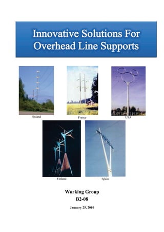
  • 1. Finland France USA Finland Spain Working Group B2-08 January 25, 2010
  • 2. he first man to place a log across a stream was probably criticized roundly by his fellow tribesmen for defacing the countryside. Today we proudly show visitors our bridges as scenic wonders-from the stately George Washington in New York to the harp-stringed Golden Gate in San Francisco. When transmission towers are given the same purity of expression given great bridges, they, too, may be acclaimed as Twentieth Century art form. Of course, there is a difference. We encounter bridges in a personal way: we cross them. On the other hand, our contact with transmission towers is remote. The only thing crossing them is electricity. And so we are conditioned, psychologically, to accept a bridge more easily than a power pole. The towers shown in this book are both simple and functional in form. Particular care was given to fitting them into their environment. Thus in preparing structures for urban areas, we studied urban surroundings and expressed them in the structures. We devoted similar attention to rural structures. All of us would prefer to place electric power underground or to transmit the power on an invisible beam. But until such techniques prove practical, we hope that the work shown here will serve usefully the dedicated designers and engineers who seek to preserve the integrity of our surroundings. Henry Dreyfuss “SOURCE” Elena Paroucheva January 1968
  • 3. Innovative Solutions for Overhead Line Supports Working Group B2-08 TASK FORCE MEMBERS Australia H. Hawes Brazil J.B.G.F. da Silva (TF Leader) Finland V. Numminen / T. Leskinen / K. Nieminen France L. Pellet Iceland E. Thorsteins Norway G. Nesgard Romania G. Gheorghita Spain J. Fernández United States L. Kempner (*)Special Contributor E. Paroucheva Convener: J.B.G.F. da Silva (Brazil), Secretary: D. Hughes (United Kingdom), Regular members: A. Fuchs (Germany), D.I. Lee (Korea), E. Thorsteins (Iceland), G. Nesgard (Norway), J.D. Serrano (R. South Africa), J. Fernandez (Spain), J. Peralta (Portugal), J. Rogier (Belgium), L. Binette (Canada), L. Kempner (United States), L. Pellet (France), N. Masaoka (Japan), R.C. Ramos de Menezes (Brazil), R. Jansson (Sweden), S. Villa (Italy), V. Numminen (Finland), Corresponding members: C.G. Alamo (Venezuela), C. Laub (Czech Republic), C. Thorn (UK), F. Legeron (Canada), F. Meza (Bolivia), G. Brown (Australia), G. Gheorghita (Romania), H Hawes (Australia), I. Magdi (Canada), J.Molé(Cuba), J. Prieto (Spain), J. Toth (Canada), K. Nieminen (Finland), K. Van Dam (Belgium), M. Vanner (UK), R. Guimarães (Brazil), T R. Peixoto (Brazil), Leskinen (Finland). Copyright © 2007 “Ownership of a CIGRE publication, whether in paper form or on electronic support only infers right of use for personal purposes. Are prohibited, except if explicitly agreed by CIGRE, total or partial reproduction of the publication for use other than personal and transfer to a third party; hence circulation on any intranet or other company network is forbidden”. Disclaimer notice “CIGRE gives no warranty or assurance about the contents of this publication, nor does it accept any responsibility, as to the accuracy or exhaustiveness of the information. All implied warranties and conditions are excluded to the maximum extent permitted by law”.
  • 4. TABLE OF CONTENTS 1. INTRODUCTION ............................................................................................................................. 7 2. EVOLUTION ON THE SOLUTIONS ............................................................................................ 8 2.1 FIRST OHL TOWER AESTHETIC STUDIES ......................................................................................... 8 2.2 CIGRÉ STUDIES ................................................................................................................................ 9 2.3 FIRST INITIATIVES .......................................................................................................................... 11 3. THE OVERHEAD LINE MONOPOLE SUPPORTS ................................................................. 12 3.1 MAIN CHARACTERISTICS ............................................................................................................... 12 3.2 STRUCTURAL CHARACTERISTICS ................................................................................................... 14 4. THE CIGRE WGB2.08 STUDIES ................................................................................................. 15 5. ADVANCED INNOVATIVE SOLUTIONS ................................................................................. 15 5.1 SOLUTIONS FOR UNIQUE PLACES: THE FINNISH EXPERIENCE ......................................................... 15 5.2 SOLUTIONS FOR SPECIFIC LINES ..................................................................................................... 19 5.2.1 The Danish Experience .......................................................................................................................... 19 5.2.2 The TL Salmisaari-Meilahti, Helsinki ................................................................................................... 22 5.3 STANDARD AESTHETIC SOLUTIONS - THE FRENCH EXPERIENCE ................................................... 27 6. OVERHEAD LINE TOWERS INTO ARTWORKS ................................................................... 29 6.1 FINNISH SCULPTURES .................................................................................................................... 29 6.2 FRENCH INITIATIVES ...................................................................................................................... 32 6.2.1 Architect / Designers’ Tower Competition............................................................................................ 32 6.2.2 Networks into Artworks ........................................................................................................................ 36 6.3 ICELANDIC STUDIES ....................................................................................................................... 43 7. ANALYSIS OF THE SOLUTIONS............................................................................................... 48 8. CONCLUSIONS .............................................................................................................................. 55 9. ACKNOWLEDGEMENTS ............................................................................................................ 55 10. REFERENCES ................................................................................................................................ 55 ANNEX A: WORLDWIDE OHL AESTHETIC SOLUTIONS......................................................... 57 4
  • 5. TABLE OF FIGURES Figure 1 – H.Dreyfuss Pictorial Index ........................................................................................................ 8 Figure 2 -H.Dreyfuss Proposal ................................................................................................................... 9 Figure 3 - H.Dreyfuss Proposal .................................................................................................................. 9 Figure 4 – Architeture School Students’ Proposals .................................................................................. 11 Figure 5 – First Aesthetic Solutions ......................................................................................................... 11 Figure 6 – Monopole Solutions ................................................................................................................ 12 Figure 7 – Typical Pole Cross-Sections & Joints ..................................................................................... 12 Figure 8 – Typical PoleFoundation Details .............................................................................................. 13 Figure 9 - Pole deflections during Tests ................................................................................................... 14 Figure 10 – SCB2.08 Country Contributors ............................................................................................. 15 Figure 11 - 1994: ”Yellow beak” - Hiversalo, Turku. A. Nurmesniemi ................................................. 16 Figure 12 - 1995: "Blue Cranes", Espoo.Studio Nurmesniemi. ............................................................... 16 Figure 13 - 1995:Petäjävesi, Virkkala. B. Selenius .................................................................................. 17 Figure 14 - 1996: Tuusula. IVO Power Engineering. ............................................................................... 17 Figure 15 - 1998: Jyvaskylan, J. Valkama ............................................................................................... 17 Figure 16 - 2000: "Antinportti”, Hämeenlinna. Studio Nurmesniemi. ..................................................... 18 Figure 17 - 2000: Ilola, Porvoo................................................................................................................. 18 Figure 18 - 2001: Rekola, Vanta,. J. Valkama.......................................................................................... 18 Figure 19 - 2003: Oulu, Kuivasjarvi. ....................................................................................................... 18 Figure 20 - New 400kV line ..................................................................................................................... 19 Figure 21 - The Winning entry – Erik Bystrup......................................................................................... 19 Figure 22 - Transition from Donau- to design-towers .............................................................................. 19 Figure 23 - The lattice top ........................................................................................................................ 20 Figure 24 - Shafts in the landscape ........................................................................................................... 20 Figure 25 - Suspention V-string ............................................................................................................... 21 Figure 26 - Angle tower ............................................................................................................................ 21 Figure 28 - TL Salmisaari-Meilahti, Helsinki .......................................................................................... 22 Figure 27 – Prototype under test ............................................................................................................... 21 Figure 29 - First pencil drawings .............................................................................................................. 22 Figure 31 - A photo montage of the transmission line ............................................................................. 23 Figure 30 – Tower CAD drawings ........................................................................................................... 23 Figure 32 – Towers Manufacturing .......................................................................................................... 24 Figure 33 – Towers Finishing ................................................................................................................... 24 Figure 34 - Body parts Assembly ............................................................................................................. 25 Figure 35 – The Interesting Result ........................................................................................................... 25 Figure 36 – Tower Top Detail .................................................................................................................. 26 Figure 37 - The “ROSEAU” Tower – M. MIMRAM .............................................................................. 27 Figure 38 - The “FOUGERE” Tower - I. Ritchie, K. Gustafson.............................................................. 28 Figure 39 - The “ARVERNE” Tower - Transel, Linuhonnun.................................................................. 28 Figure 40 - Lempäälä.Konehuone / J. Valkama ....................................................................................... 29 Figure 41 – Nummela, Vihti. Konehuone/J. Valkama. ............................................................................ 30 Figure 42 - Vaasa, Palosaari. Konehuone/J. Valkama.............................................................................. 30 Figure 43 - Espoo, Suurpelto. Konehuone/J. Valkama. ........................................................................... 30 Figure 44 – “Antti’s Steps”, Helsinki. A. Nurmesniemi & J. Valkama ................................................. 31 Figure 45 - Eurajoki. Konehuone/J. Valkama. ......................................................................................... 31 Figure 46 - Well-Thought Reeds.Marc Mimram ...................................................................................... 32 Figure 47 - “f”s All The Way-Ritchie, RFR, Gustafson........................................................................... 33 Figure 48 - Slender Stabile. Deslaugiers, RFR,Gerpa Team .................................................................... 33 Figure 49 - “Ecosystem. Wilmotte, Technip, Petit-JeanTeam ................................................................. 34 Figure 50 - Card Game.Perrault, Ove Arup Team.................................................................................... 34 Figure 51 – Swan Neck.Euro RSCG Design,Tallon,Bet Jean Muller International Team ...................... 34 5
  • 6. Figure 52 - The Heron Aesthetics.Giugiaro Design Team ....................................................................... 35 Figure 53 – Haute Couture.Starck,Meda, Arsene-Henry and Triaud, de Miranda Team ......................... 35 Figure 54 - Art Installations on Overhead Line Supports......................................................................... 36 Figure 55 - Towers Sculptures .................................................................................................................. 36 Figure 56 - Sculptures- Electric Tower Models ....................................................................................... 37 Figure 57 - Sculptures- Cellular Antennas ............................................................................................... 37 Figure 58 - Amnéville-les-Thermes Location .......................................................................................... 38 Figure 59 – E. Paroucheva’s Studies ........................................................................................................ 38 Figure 60 - Erection of the artwork of ”Source” ...................................................................................... 39 Figure 61 - “Art Installations” Works on “Amnéville-Mortois OHL” ..................................................... 40 Figure 62 – Aesthetic Works on Amnéville-Mortois OHL .................................................................... 41 Figure 63 – “Source Lumière” – Pylon nº 10 ......................................................................................... 41 Figure 66 - “Source Flame” – Pylon nº 13 ............................................................................................. 42 Figure 64 - “Source Energy” – Pylon nº 12 ............................................................................................ 42 Figure 65 – “Source Water” – Pylon nº 11 .............................................................................................. 42 Figure 67 – “Walking Giants” –The Winner ............................................................................................ 44 Figure 68 – “Superstring” ......................................................................................................................... 45 Figure 69 – Landscape Tower Proposal ................................................................................................... 45 Figure 70 - Landscape Tower Proposal .................................................................................................... 46 Figure 71 - Landscape Tower Proposal .................................................................................................... 46 Figure 72 - Landscape Tower Proposal .................................................................................................... 47 Figure 73 - Landscape Tower Proposal .................................................................................................... 47 Figure 74 - Landscape Tower Proposal .................................................................................................... 48 Figure 75 – Tower Solutions for long OHL ............................................................................................ 49 Figure 76 - 1992 Seville Expo Tower - Spain ........................................................................................ 49 Figure 77 - Vaasa, Palosaari. Konehuone / J. Valkama........................................................................... 50 Figure 78 – Hameenlinna Landscape Tower .......................................................................................... 51 Figure 80 - The McDonald’s towers ........................................................................................................ 52 Figure 79 – The Mouse Head Tower ...................................................................................................... 52 Figure 81 – “Haute Couture pour Pylônes de Haute Tension” ................................................................. 53 Figure 83 – “Source Eau” – Pylône nº 11 ................................................................................................. 53 Figure 82 – “Towers and Arts” ................................................................................................................. 53 Figure 84 – The “Pagoda” Tower ............................................................................................................. 54 Figure 85 – The “Big Hat Towers”........................................................................................................... 54 ANNEX A - FIGURES A1. AUSTRALIA .................................................................................................................................. 59 A2. BRAZIL .......................................................................................................................................... 62 A3. CANADÁ ........................................................................................................................................ 67 A4. DENMARK ..................................................................................................................................... 69 A5. FINLAND ....................................................................................................................................... 71 A6. FRANCE ......................................................................................................................................... 75 A7. ICELAND ....................................................................................................................................... 75 A8. ITALY ............................................................................................................................................. 88 A9. JAPAN ............................................................................................................................................ 82 A10. NORWAY ....................................................................................................................................... 95 A11. ROMANIA ...................................................................................................................................... 96 A12. SOUTH AFRICA .......................................................................................................................... 100 A13. SPAIN ........................................................................................................................................... 101 A14. SWEDEN ...................................................................................................................................... 106 A15. SWITZERLAND .......................................................................................................................... 108 A16. UNITED KINGDOM .................................................................................................................... 110 A17. UNITED STATES ........................................................................................................................ 112 6
  • 7. 1. INTRODUCTION Years ago, aesthetics was not a value taken into account in the design of supports for new transmission lines. Towers were not judged as “pretty” or “ugly”; they were just considered essential elements for transmission of electricity. Many thousands of kilometers of transmission lines were, thus, built in all continents, justified by the benefit of the electricity, considered a privilege of modern societies organized in cities and factories with high consumption of energy. This reality started to change mainly after the 60’s, when the environmental aspects of the lines and the aesthetics of the supports, began to be more and more questioned in the implementation of new designs. These changes can be understood as a result of many factors, such as: - The existence of thousands of kilometers of lines already built in some countries and/or some regions. - The evolution of the benefit of electricity, from “a privilege of few societies” to an “acquired right” of the citizens of the twentieth century. Electricity subtly became a “social right”, and an obligation of the governments to provide it. - The increasing presence of transmission lines in inhabited areas, in such a way, that the towers became familiar elements in the cities. - The difficulty of obtaining new urban corridors for bringing more power to central regions of cities especially those with high vertical growth. - A greater environmental conscience motivated by the various aggressions to the environment in different regions of the world. All this together made that the environmental aspects had become one of the most important premises in the studies for the implementation of new transmission lines. Nowadays, transmission line projects have to start with an environmental impact assessment, where environmental auditors identify and analyze the impacts on the natural and human environment. New line routes have to find a balance between the need of electricity transmission and the environmental perspectives. As part of these studies, the visual appearance and the aesthetic of the towers began to play an important role in the analysis, once they are the most visible elements on the landscape. This Technical Brochure, through a research conducted by the Cigré WGB2.08, has the purpose of reporting how these questions have been treated and solved recently around the world. It will also be shown, how aesthetic towers have been used as solution to mitigate environmental impacts. 7
  • 8. 2. EVOLUTION ON THE SOLUTIONS 2.1 First OHL Tower Aesthetic Studies The subject of the aesthetic of transmission line towers is not a new issue. During the 60’s, designers and power lines engineers had already started to study improvements on their aesthetics. One of the first remarkable initiatives was the studies reported by H. Dreyfuss & Associates, through a publication of Edson Electric Institute in 1968 [1]. The document contains 47 innovative proposals for Overhead Line Supports with different conductor configurations, with single or double circuits, and using different materials such as steel, concrete or wood. Outstanding aesthetic solutions were suggested, perhaps a little advanced for their time, but with a clear vision of the future (figures 1, 2 and 3). Figure 1 – H.Dreyfuss Pictorial Index 8
  • 9. Figure 2 -H.Dreyfuss Proposal Figure 3 - H.Dreyfuss Proposal The Dreyfuss’ studies were carried out in times when more and more power lines began to cohabitate with citizens and cars on the cities, disputing their urban space. Transmission lines had to bring more power to the downtown of big cities growing vertically, and/or cities expanding horizontally reaching existing servitudes of lines already constructed. For these reasons, in different parts of the world, Utilities have started to think more and more seriously on the aesthetic of the overhead line supports. 2.2 Cigré Studies Due to the increasing environmental concerns regarding the impact of overhead lines, and consequently the necessity of discussing solutions to mitigate them, the former Cigré SC22, in the beginning of the 80’s, created the Working Group 02 focusing on the environmental aspects of the lines. This group finalized its works in 1986 publishing the Technical Brochure “The Environmental Impacts of High- Voltage Overhead Transmission Lines”[2]. Many new ideas and suggestions were presented in that Brochure, showing how it is possible to minimize impact of the overhead lines through creative proposals for land occupation. Later on, in 1999, another Technical Brochure entitled High Voltage Overhead Lines-Environmental Concerns, Procedures, Impacts and Mitigations (Technical Brochure nr. 147), was published by Cigré, enlarging the discussions about OHL routes and corridors, visual impact and mitigation measures[3]. 9
  • 10. Motivated by the Cigré studies, in 1988, J. da Silva(Cigré former SC22 member) carried out an interesting survey in the Architectural School of the Federal University of Minas Gerais, Brazil, on the environmental aspects of the Overhead Lines. Forty students, splitted in eight small groups, were invited to investigate the visual impact of the overhead transmission lines crossing the outskirts of the city of Belo Horizonte, Brazil, with specific focus on the aesthetic of the towers. The unique demand to them was the visual aspect, the aesthetic, the beauty of the towers, and/or their impact on the landscape. There was no involvement on economy aspects, and no engagement with the necessity of energy transportation. Eight reports were produced revealing interesting perspectives from the vision of the common citizen, and in this particular case, also from qualified citizens with an already acquired capability of making critical analysis in terms of aesthetic. From this exercise, the following comments were considered relevant, being interesting to be noted: • “To be honest, we should assume that we have never paid attention to this matter before”. • “In our cities, in general, there are many other constructions that have worse visual impact than the towers”. • “From the architectural point of view, the transmission lines are characterized by the presence of the vertical element”. • “Concerning the visual aspect of the transmission lines, all attention should be given to the towers. They should be treated as if they were sculptures”. • “Looking a little bit closer and paying more attention, we could verify that there are beautiful and ugly towers”. • “The towers cannot be ignored in the context: They should be camouflaged or exhibited”. • “There are green and brown insulators. The green insulators are more beautiful”. • “In special locations in the cities, the towers should be painted with live colors: lemon-green, shock-pink, blood-red, electric-yellow, etc.” (Figure 4) • “Some towers could be used to decorate the cities like in Christmas Season by dressing them with chains of lights. Some others could also be used to support cable cars in parks and in other recreational areas”. (Figure 4). • “The majority of the towers we found were latticed ones, but there are others from a more compact type. • “From the aesthetical point of view, the most interesting tower we found was that from the compact type with box section like poles! They are slender, having an agreeable aspect and requiring a reduced base area to be settled”. • “It is a pity, but we were informed that, as a general rule, the architects don’t participate in the transmission line projects”. • “A sample of the population should be consulted about the preferable type of towers to be specified. We think that, if they were involved, they could accept more easily the existence of the transmission lines”. 10
  • 11. Figure 4 – Architeture School Students’ Proposals 2.3 First Initiatives The first practical initiatives in terms of “aesthetic towers” were not so ambitious and, basically, oriented by the following principles: - To compact the lines and the supports as much as possible, - To reduce the number of structural elements on the towers, - To try to put them invisible or camouflaged in the landscape. The compact solutions like the monopoles, the portal and V guyed, the chainette and the “cross-rope suspension - CRS”, were solutions that have fulfilled with those objectives (Figure 5). Thousands of kilometers of lines were constructed around the world using these solutions, which aesthetic principles were based on simplicity, slenderness, symmetry, invisibility, reduced number of structural elements, transparence. Monopole Support Portal Guyed Invisible Cross rope Brazil Sweden Argentina Figure 5 – First Aesthetic Solutions 11
  • 12. 3. THE OVERHEAD LINE MONOPOLE SUPPORTS The most attractive solution for urban or suburban OHL towers has been the monopole supports. They have been extensively used in all over the world, having adaptations and characteristics according to local necessities. There are many reasons for the extensive use of monopoles as the main aesthetic solution. Among them it can be noteworthy: the simplicity, the slenderness, the low visual impact, the elegance, the beauty and the reduced area for settlement. As a summary, they are attractive solutions having appropriate painting system to fit them into special environmental circumstances (Figure 6). Monopole Support Aesthetic Pole Compact Plus - Top insulated Support Brazil Japan Sweden Figure 6 – Monopole Solutions 3.1 Main Characteristics Currently, the steel poles are made from carbon steel, mainly from high strength low alloy quality, being shaped in modulus from 9 up to 12m length and with continuously variable polygon cross sections. Depending on the dimensions involved (height and pole base width), the cross section used can be from the square (or rectangular) to the dodecagonal or circular type (Figure 7). The most common joints used are from the “overlapping splices” type, more suitable for suspension or light angle poles. The flanged joints are currently used for the heavy angle or dead-end poles (Figure 7). SQUARE HEXAGONAL OCTAGONAL DODECAGONAL CIRCULAR Overlapping Flanged Figure 7 – Typical Pole Cross-Sections & Joints 12
  • 13. The finishing types are specified basically to meet two needs: the corrosion protection and the aesthetic. For this purpose, the poles can be only externally painted with complete sealed joints, or hot-dip galvanized. The first solution provides an excellent aesthetic finishing, while the second one excellent protection. Therefore, some clients usually specify both finishing procedures, hot-dip galvanizing plus painting to obtain both advantages. For this, it is mandatory to use an appropriate “shop primer” over the galvanized coating in order to create a sufficient / necessary anchorage surface. As far as the pole foundations are concerned, they have been constructed using two different principles: the “direct embedment” or the “flanged base plate with anchor bolts”. The directly embedment on densed sand box, is a very economic solution mainly when designed for light suspension poles. The flanged base plate proposal is specially recommended for angle/dead-end poles, since the “two nuts adjustable system” helps to adjust the pole top deflection (Figure 8). Top seal Nuts for adjusting Densed sand Anchor bolt templates Sand box directly embedment type Flanged base plate type Figure 8 – Typical PoleFoundation Details 13
  • 14. 3.2 Structural Characteristics From the structural analysis point of view, it is important to observe that the monopoles are very flexible structures with high level of elastic deformation (up to 5% of the height or even more) especially when compared with similar latticed towers. For this reason, it is recommended that the calculations should be carried out through “physical and geometric non linear” analysis. Second order effects, may be of great relevance in the case of structural analysis for monopoles. To limit pole top deflection, however, can be very expensive. For this reason, to reach both aesthetic and economic targets, it is suggested to verify the pole top deformation at the following stages: - At EDS condition: maximum top deformation equal or smaller than 1.5 to 2% of the pole height, - At Ultimate Stage: 4 to 5% of the pole height. Figure 9 illustrates how deformable are the monopoles during the prototype tests. Figure 9 - Pole deflections during Tests 14
  • 15. 4. THE CIGRE WGB2.08 STUDIES During the 90’s, the aesthetic of the OHL towers became a real issue in some regions, and the first “landscape towers” were installed. New approaches and techniques were applied envisaging a better public acceptance. Aiming to collect all those new ideas, the Cigré WGB2.08 created a new Task Force entitled “Innovative Solutions for Overhead Line Supports”. The main objective of this new TF was to collect all the initiatives around the world on aesthetic towers, and to produce a Brochure that could be a reference book. Contributions were received from 17 countries: Australia, Brazil, Canada, Denmark, Finland, France, Iceland, Italy, Japan, Norway, Romania, South Africa, Spain, Sweden, Switzerland, United Kingdom and United States(Figure 10). All contributions were equally received as innovative and aesthetics. An interesting databank was created showing the great variety of aesthetic solutions adopted in different parts of the world. The solutions collected can be seen on the Annex A attached to this Brochure. Australia Iceland Spain Brazil Italy Sweden Canada Japan Switzerland Denmark Norway United Kingdom Finland Romania United States France South Africa Figure 10 – SCB2.08 Country Contributors 5. ADVANCED INNOVATIVE SOLUTIONS Analyzing the solutions reported on the data bank, it could be identified that the so called “aesthetic proposals” already adopted by the Utilities, follow three basic principles: to design aesthetic solutions for unique places, for a single line, or standard aesthetic solutions. Examples of these trends can be found, for example, in Finland, in Denmark and in France. 5.1 Solutions for unique places: The Finnish Experience In Finland, there are good examples of unique tower solutions for specific places. The first landscape towers were constructed in the early 90's by Fingrid Plc, the national grid operator in Finland. The company wanted to get better public acceptance for the lines and, in some cases, to use them as landmarks in public places. Fingrid hired for that purpose a well-known interior architect, Prof. Antti Nurmesniemi to look at structures from a designer's point of view. The idea of Nurmesniemi was not to hide the towers into the environment but, quite the opposite, to exhibit them. He wanted to show that transmission line structures are not only functionally necessary objects but can also be visually attractive and, in some cases, seen almost like pieces of art. First landscape towers were installed in 1994, in the Southwest of Finland coast in the city of Turku. It was a series of six towers, the design of which was matched with the gabled one-family houses of the residential area nearby. Colour schemes were inspired by the surroundings (Figure 11). 15
  • 16. Figure 11 - 1994: ”Yellow beak” - Hiversalo, Turku. A. Nurmesniemi Few years later, a multi-level junction in Espoo was provided with a unique landmark and piece of environmental art: a series of three 400 kilovolt towers, referred to as “Espoon sinikurjet” (Blue cranes of Espoo) on account of their blue colour, (Figure 12). Figure 12 - 1995: "Blue Cranes", Espoo.Studio Nurmesniemi. After this, towers adapted to the surroundings were erected at the cities of Virkkala (Figure 13), Tuusula(Figure 14), Jyvaskylan (Figure 15), Hameenlinna(Figure 16), Porvoo (Figure 17), Vantaa (Figure 18) and Oulu(Figure 19) [4]. 16
  • 17. Figure 13 - 1995:Petäjävesi, Virkkala. B. Selenius Figure 14 - 1996: Tuusula. IVO Power Engineering. Figure 15 - 1998: Jyvaskylan, J. Valkama 17
  • 18. Figure 16 - 2000: "Antinportti”, Hämeenlinna. " Figure 17 - 2000: Ilola, Porvoo. Studio Nurmesniemi. Studio Nurmesniemi. Figure 18 - 2001: Rekola Vanta,. J. Valkama. Rekol Rekola, J Figure 19 - 2003: Oulu, Kuivasjarvi. 18
  • 19. 5.2 Solutions for specific lines The most common approach for reaching environmental friendly power lines, is to propose an aesthetic solution for a specific line (or just a segment of the line) which crosses a sensitive region. A good example of that, is the 400kV connection line between the cities of Aarhus and Aalborg in Denmark. Another remarkable case is the transmission line Salmisaari-Meilahti in Helsinki, Finland. 5.2.1 The Danish Experience According to [5], “Eltra is the system operator for the western part of Denmark and owner of 400 kV grid. In March 2001, Eltra received a license to construct a new 400 kV connection between the cities of Aarhus and Aalborg, finalizing a major 400 kV ring (Figure 20). This connection consists of overhead lines (117 km) with intermediate sections of underground cables (14 km). A minor part of the connection (27 km, shown on the map in green) is placed going through a rural area with few technical installations. For this part the Danish Minister for Energy decided to demand a new type of tower based on a design competition. Figure 20 - New 400kV line The winning entry, selected from among 48 entries, was based on a tower with a cylindrical shaft of weathering steel and a tower top constructed as a lattice structure built of very few tubular members, all in stainless steel (Figure 21). Figure 21 - The Winning entry – Erik Bystrup The overall design strategy for the new 400kV tower was to design a tower which, unlike the existing Donau towers, did not add visual “noise or interference” to the landscape. It is a tower consisting of few elements and simplicity in the design. A tower that would be read as aesthetic, calm, and repetitive elements strolling through the landscape contours. (Figure 22). To achieve this, a hierarchy on how a technical installation is perceived in the landscape was developed: -At a distance, only the body of the poles is visible, standing quietly measuring out the landscape. -A little closer the insulators, the high voltage strings and the lattice top become visible. -Close on the tower the details of the lattice top, the joints, the Figure 22 - Transition from Donau- to connections and the electrical components become visible. design-towers 19
  • 20. To support this hierarchy a choice of materials for the different elements was suggested: Weathering steel for the shaft and Stainless Steel for the lattice top (Figure 23). Figure 23 - The lattice top Thus, in colour and texture the weathering steel becoming to the soil and the Stainless Steel lattice top becoming part of the sky. Together these materials would strengthen each other giving character to both elements and underline the design strategy. Due to local public opposition, the weathering steel for the shaft was abandoned and replaced with hot dip galvanized steel. (Figure 24). Figure 24 - Shafts in the landscape The new 400 kV tower accomplishes a variety of assignments in one unique design: - Creating a continuous visual appearance, thus, - Minimizing the visual impact on the landscape. - Angle tower capabilities allow a harmonious, ”bent” alignment of overhead line and landscape. - Due to a straight-forward and inexpensive foundation method, the tower leaves a minimal footprint. - Fitting lattice tubes with cast stainless steel joints allows faster in site assembling. - The overall design allows a reduction of the magnetic fields. One of the main adjustments of the winning entry was to change the vertical strings to V-strings in order to be able to use the same tower as a suspension tower and as a running angle tower for minor angles, to lower magnetic fields and to achieve a narrow right of way (Figure 25, 26). The tower head is constructed as a lattice structure of stainless steel tubes welded together. The joints of the tubes are casted in stainless steel. Developing the moulds for the castings and executing the castings were difficult tasks due to the complicated geometry. 20
  • 21. Figure 25 - Suspention V-string Figure 26 - Angle tower A tower family with 3 types of supports was developed: - Suspension tower - Running angle tower for max. 5º deflection - Angle tension tower for 5 to 45º line angle A prototype of the suspension tower was constructed and mechanically tested up to 105% of the maximum design loads (Figure 27). Figure 27 – Prototype under test 21
  • 22. 5.2.2 The TL Salmisaari-Meilahti, Helsinki The towers for the transmission line between Salmisaari and Meilahti are located in the sea area in front of the urban Helsinki district (Figure 28). Figure 28 - TL Salmisaari-Meilahti, Helsinki The line is 3.5 km long, and it includes nine new towers being 5 of them, the ones located on the sea area, landscape towers designed by Prof. A. Nurmesniemi (Figures 29, 30, 31). The TL Salmisaari-Meilahti, Helsinki Figure 29 - First pencil drawings 22
  • 23. Figure 30 – Tower CAD drawings Figure 31 - A photo montage of the transmission line Due to the line's central location, it was the wish of the client, Helsinki Energy, to use these environmentally amenable structures. Design and construction of foundations are generally very difficult in offshore sites. In this line, two offshore towers were based on piled foundations. The longest piles used had 21 m with 610 mm of diameter. The tension capacity was secured by drilling and 23
  • 24. grouting the bar (length of 5 m) into the rock. After the concrete hardening, the tension capacities of the piles were tested. The foundations themselves were made in the traditional way: with “pad and chimney” and casting in dry circumstances. In order to keep the water away from the foundation works, and to enable the underwater constructions, a steel coffer was used. A temporary bridge was constructed for moving piling machine and the coffer to the place of the tower. Special attention was paid on the positioning of the anchor bolts (16 pcs/tower leg). The profiles used on the fabrication of the landscape towers were not of a standard type. Suitable manufacturing method had to be chosen. A half oval profile was made from two pieces which were fabricated by using a trimming press. Half profiles were welded together using a submerged arc welding against backing. The maximum length of tower parts was designed not to exceed 12 m (Figure 32). Figure 32 – Towers Manufacturing The erection of the towers had to be designed in such a way that the weight of the single parts did not become too heavy. All joints between body parts were bolted with flange connections. Special lifting and guiding devices had to be designed in order to get two leg parts assembled together (Figures 33, 34). Figure 33 – Towers Finishing 24
  • 25. Figure 34 - Body parts Assembly Upper parts were lifted as single modules while an additional frame had to be designed so that the members could be assembled to body parts (Figures 35, 36). Figure 35 – The Interesting Result 25
  • 26. Figure 36 – Tower Top Detail 26
  • 27. 5.3 Standard Aesthetic Solutions - The French Experience To develop “standard aesthetic tower solutions” is one of the approaches used by RTE, the French Transmission Grid Operator, for the integration of Overhead Lines into the environment. Aiming to reach this objective, RTE has promoted two experiences for development of innovative supports: the architects and the tower manufacturers design competitions. The first architects design competition was carried out in 1994 and had, as main target, to develop standard aesthetic solutions for 400kV Overhead Line Towers, to be used when and where it would be necessary. As per [6], the specifications were very limited without any restriction, for example, to the selection of materials to be used or phase arrangements. The only exception was the attendance to the electrical clearances. The objective of this first experience was to give, as much freedom as possible to the creativity of the designer. In most of the cases, the proposals were made by architects in association with technical engineers. At the end of the process, eight competitors were selected among 121 candidates and two winners appointed. The jury was composed by RTE representatives, as well as members of the fields of architecture, design and environment. The competition process lead to the definition of two standard aesthetic tower families: the “Roseau (reed)” and the “Fougère (fern)”. The “Roseau”, designed by M. Mimram, is a slender structure, exploring the verticality of the support element. An original technology was used based on open-work modules of casting material for the lower part of the tower (Figure 37). Eleven Roseau type towers have been installed in France so far. Photo montage Real Figure 37 - The “ROSEAU” Tower – M. MIMRAM The “Fougère” type support was designed by I. Ritchie and K. Gustafson (RFR Architects), and consists of a tube tower whose originality lies on the distribution of conductors in a horizontal position spread over two independent structures in the shape of an “f”. In this solution the architects were looking for a very pure form (Figure 38 ). Two Fougère towers have already been installed in France. 27
  • 28. Photo montage Real Figure 38 - The “FOUGERE” Tower - I. Ritchie, K. Gustafson The main advantage of this first RTE experience was the great innovation in shapes obtained. As disadvantages, it can be appointed the difficulty to transform a concept into industrial product, the time taken for development and tests, and the high costs involved. All these lead to limit the use of that aesthetic towers to exceptional sites. The second experience was proposed only among support manufacturers and performed along 2004/2005. Differently from the architects’ competition of ten years ago, in this case, the functional specifications were more restrict. It were defined the position of the phases, the number of circuits (single or double), the materials to be used and suggestions of silhouette. The main objective of this le experience was to obtain a tower design on the basis of technical solutions, thus, avoiding industrialization difficulties. This way, the proposals were expected to come from the industry, either OHL manufacturer or pylon suppliers. The advantages of that procedure were basically the use of tested/existing solutions, with little industrialization difficulties, reduced development times and at reasonable costs. The main disadvantage, as compared with the architects’ competition, is that, the creativity is reduced and, as a consequence, the innovation is much more limited, resulting in shapes and formats more traditional. With this procedure, a new wood support was developed for using in the 225kV OHL of RTE named as “The Arverne”. The prototype tower was a proposal from Transel - Linuhonnun team, and 78 pylones were installed in France in 2005 (Figure 39). Figure 39 - The “ARVERNE” Tower - Transel, Transel 28 Linuhonnun
  • 29. 6. OVERHEAD LINE TOWERS INTO ARTWORKS The various experiences carried out in the world with aesthetic towers were, generally, very successful in terms of public acceptance. Those initiatives motivated the Utilities that had lines in sensitive areas, to expand the concepts and the use of “landscape towers”. Since the 90’s, slowly, the towers were evolving from OHL Supports to “Urban Electrical Sculptures”, as envisaged by H. Dreyfuss’ Studies and Da Silva’s architecture students Consultation, in 1968 and 1988 respectively (see items 3.1 and 3.2). 6.1 Finnish Sculptures In Finland, according to [7], “the transmission line towers designed by Studio Nurmesniemi represent a straightforward design approach. The towers have an important downright vital purpose as a part of the electricity transmission system, and their design naturally stems from proper functionality. In large objects, an aesthetic appearance often means eliminating details; this is also the case with these towers. The towers adapted to their background scenery and to the built-up environment represent technical aesthetics at its best.” After the well succeeded first experiences, landscape towers have continued to be designed and constructed. As examples, Figures 40, 41, 42, 43, 44 and 45, show new solutions in the cities of Lempäälä, Vihti, Vaasa, Espoo, Helsinki, Eurajoki, that are really sophisticated sculptures used as towers to support conductors [4]. Figure 40 - Lempäälä.Konehuone / J. Valkama 29
  • 30. Figure 41 – Nummela, Vihti. Konehuone/J. Valkama. Figure 42 - Vaasa, Palosaari. Konehuone/J. Valkama Figure 43 - Espoo, Suurpelto. Konehuone/J. Valkama. Konehuone/ Konehuone/J 30
  • 31. Figure 44 – “Antti’s Steps”, Helsinki. A. Nurmesniemi & J. Valkama Figure 45 - Eurajoki. Konehuone/J. Valkama. 31
  • 32. 6.2 French Initiatives In France, to mitigate overhead line impacts, EDF/RTE has adopted the philosophy of “the best integration into the environment at a reasonable cost”. Currently, such integration is achieved by means of: - The best route selection for the line, - Aesthetic towers when necessary, - Specific paintings or artistic treatment of lattice towers. 6.2.1 Architect / Designers’ Tower Competition For developing “aesthetic towers”, as seen in item 6.3, RTE has promoted architects/designers’ competitions. As per [6], from the first competition carried out in 1994, when as much freedom as possible was given to the proponents, eight solutions were chosen as most innovative and aesthetics among 121 proposals. The photomontage of them can be seen on figures 46, 47, 48, 49, 50, 51, 52, 53. Figure 46 - Well-Thought Reeds.Marc Mimram 32
  • 33. Figure 47 - “f”s All The Way-Ritchie, RFR, Gustafson Figure 48 - Slender Stabile. Deslaugiers, RFR,Gerpa Team 33
  • 34. Figure 49 - “Ecosystem. Wilmotte, Technip, Petit-JeanTeam Figure 50 - Card Game.Perrault, Ove Arup Team Figure 51 – Swan Neck.Euro RSCG Design,Tallon,Bet Jean Muller International Team 34
  • 35. Figure 52 - The Heron Aesthetics.Giugiaro Design Team Figure 53 – Haute Couture.Starck,Meda, Arsene-Henry and Triaud, de Miranda Team Looking at these solutions chosen by the Selection Committee, it can be perceived that they are more “sculptures” than towers and, not by a coincidence, at the end of the selection process, the two winners (Figures 46 and 47) were exactly those more OHL Towers oriented. “Artworks” and “Engineeringworks” were side by side on the definition of the “Standard Aesthetic Solutions” in France. 35
  • 36. 6.2.2 Networks into Artworks A new technique has been recently utilized by RTE for improving the aesthetic of the transmission Lines: The artistic treatment of lattice towers by Elena Paroucheva. The works of E. Paroucheva aim at emphasizing the above ground networks such as, energy transmission and distribution, renewable energy windmills, cellular relay–antennas, lighting–highways, stadiums, public spaces, etc. Instead of trying to hide the support elements of these facilities in the landscape, she transforms them into “artworks”[9]. Generally, she applies two kinds of techniques: “Art Installations” and “Sculptures”. The “Art Installations” solutions treat the transformation of existing infrastructures elements or buildings in the environment. They are investigated according to their reception areas and allow the modification of their visual aspect into artistic works (Figure 54). Figure 54 - Art Installations on Overhead Line Supports The “Sculptures” explore new forms of towers to be implanted in the landscape, in both urban and rural areas (Figure 55). Figure 55 - Towers Sculptures 36
  • 37. The sculptures use "symbolically" the same modules of metallic constructions for the conception of “pylons – sculptures”, “antennas – sculptures”, “wind energy – sculptures” and “lighting – sculptures”(Figures 56 and 57). Figure 56 - Sculptures- Electric Tower Models Figure 57 - Sculptures- Cellular Antennas 37
  • 38. In the city of Amnéville les Thermes, France (figure 58), "SOURCE", the artwork of E. Paroucheva, has transformed 1.3kms of an existing segment of line into a monumental piece of art[10]. At its inauguration in 1950, the 225 kV "Amnéville-Montois" line, crossed a former heap of steel in Lorraine. Afterwards, a tourist and thermal centre has been developed around the line creating, thus, a complaint from the population and the 5 million tourists that currently visit the city per year. Figure 58 - Amnéville-les-Thermes Location In 2003, an agreement was signed between RTE and the City of Amnéville-les-Thermes, for the implementation of an artistic treatment of the line. Rather than burying the line and removing the towers, the choice made was exactly the opposite, to highlight them in the landscape. The artist E. Paroucheva was then contacted and her artwork "SOURCE" implemented, transforming the existing transmission line and its 4 support towers in “dressed illuminated creatures” (Figure 59). Figure 59 – E. Paroucheva’s Studies The technique has utilized guy wires and stay cables and tubes of stainless steel over the high-voltage structures, comprising 3 km of steel cables, 2.71 km of stays, 525m of plastic canvas, 576m of stainless steel tubes, 384 fixations and 40 floodlights controlled by satellite. 38
  • 39. The 4 towers of the segment of line crossing the village, numbers 10, 11, 12 and 13 were nominated, "Source - light", "Source – water”, "Source – energy” and "Source - flame" respectively. The realization of the works has comprehended casting foundations, painting of the pylons, assembling of the guy wires and the dressing of the towers up down to their feet. Each installation has been highlighted by monochrome illumination on the ground, ordered by satellite to illuminate the work at nightfall (Figure 60). Figure 60 - Erection of the artwork of ”Source” Figure 61 shows the four towers of the “Amnéville-Mortois OHL” before and after they were treated by the works of “Art Installations”, while the figures 62, 63, 64, 65 and 66 exhibit the complete works and the results. 39
  • 40. Figure 61 - “Art Installations” Works on “Amnéville-Mortois OHL” 40
  • 41. Figure 62 – Aesthetic Works on Amnéville-Mortois OHL Figure 63 – “Source Lumière” – Pylon nº 10 41
  • 42. Figure 64 - “Source Energy” – Pylon nº 12 Figure 65 – “Source Water” – Pylon nº 11 Figure 66 - “Source Flame” – Pylon nº 13 42
  • 43. 6.3 Icelandic Studies Another interesting initiative that results in outstanding proposals of “electrical sculptures” for OHL Supports, was that carried out in Iceland by Landsnet. Again, this was done through a competition among architect/artist and engineer/designer teams. According to [8], “the competitors’ goal was to look for new types of towers, that would blend well into the environment and, thus, minimize the visual impact that the line towers undeniably have. In addition, emphasis was placed on minimizing electrical and magnetic fields. The Selection Committee has considered that, the majority of the proposals received for the competition, have fully addressed these goals. In addition, the Selection Committee has also found the competitors’ diverse approaches regarding the appearance and visual impact of the transport structures especially interesting. The competitors have chosen to either, glorify the towers, or blend them carefully into the landscape and urban areas. It is the Selection Committee’s view that both approaches have their place, and the competitors have succeeded well in showing the diversity of possibilities. The competitors’ goal was to obtain new ideas on types and appearances of a tower or towers for 220 kV high-voltage lines. Landsnet emphasized that specific consideration should be given to the visual impact of towers (or lines), and that the competitors make proposals on the appearance of towers that would take this into account as much as possible, regarding towers or lines both near urban areas and in unsettled regions. It was left up to the competitors whether all the towers would have a new look, particular towers and selected environments would have a new or altered look, or whether the appearance of known types of towers would be altered, one way or another. In addition, it was left up to the competitors whether the tower/towers were blended well into the landscape in rural and urban areas, or the tower/towers would stand out at specific sites”. The main goal of the competition was that an idea for a new type of tower/towers would emerge, an idea on the overall appearance of line routes, and that a proposal would emerge on a tower/towers that could be developed further with respect to environmental impact, the electromagnetic field, lifetime and costs.” A total amount of 98 proposals were received from different regions of the world. The eight winner solutions (in real order) selected are shown in the figures 67, 68, 69, 70, 71, 72, 73 and 74, where it can also be seen the Selection Committee’s arguments justifying their choice. 43
  • 44. Figure 67 – “Walking Giants” –The Winner S. Krehn Comment: Extremely beautiful and living support structure. “The walking giant” takes its basic structure from the human body without becoming particularly anthropomorphized. The beauty springs from utility, but the artistic purpose is not far ahead. The proposal nevertheless suffers from limited installation, which is entirely out of step with the precious content. Technical opinion: A technically possible solution that needs further development regarding the hanging of insulator suspensions and Guy wires. 44
  • 45. Figure 68 – “Superstring” Yong-ho Shin Comment: A very dynamic and innovative form of support structure and extremely exquisite connection between crossbars and the main support structure. These towers are prominent structures with artistic value. The artistic implementation could go well in demarcated areas. Technical opinion: Technically doable Figure 69 – Landscape Tower Proposal Bystrup Archtects and Designers Comment: An especially well implemented proposal. The proposal provides for the insulators being utilized as part of the support structure. Such an arrangement would have a revolutionary impact on the development of high-voltage line towers. Falls technically short regarding implementation of insulators. Technical opinion: For the tower to meet electrical requirements, the core must be made of insulating material. Today it is not possible to manufacture a sufficiently strong core with respect to the strength required for the stress that must be expected. 45
  • 46. Figure 70 - Landscape Tower Proposal T. Leung Comment: Simple, innovative and strong proposal. Offers extensive possibilities for emphasizing line routes in selected locations. Technical opinion: The insulation system is not realistic and must therefore be further developed as to how power lines go through the tower and are not isolated from it. The support structure also requires development. Figure 71 - Landscape Tower Proposal Hornsteinar arkitektar ehf Comment: Very good presentation. Towers well formulated as a convincing line support structure. It would fit well into the environment visually. Technical opinion: Technically developed solution. 46
  • 47. Figure 72 - Landscape Tower Proposal J. Winchester Comment: Revolution, vision or science fiction? There is no possibility of orienting oneself to how realistic this proposal is within the time we are given. The proposal is nevertheless admirable, and it is clear that resolving energy and environmental affairs in an idealized oscillation was very much on the author’s mind. Figure 73 - Landscape Tower Proposal T. Shine Comment: An ingenious Idea as a reference to giants in folktales and robots in modern times. Technical opinion: Technically possible. The support system requires more work. 47
  • 48. Figure 74 - Landscape Tower Proposal Bystrup Archtects and Designers Comment: Singularly simple but thoroughly thought-out proposal. Each tower would have a strong artistic impact on viewers, not least at close quarters. The delicate design makes the towers nearly invisible from a distance except perhaps on bright, sunny days when the steel glint. Technical opinion: Technically possible. 7. ANALYSIS OF THE SOLUTIONS Analyzing the aesthetic solutions collected, and the arguments justifying them, interesting aspects can be reported. Firstly, it can be observed an increasing environmental concern in almost all new OHL projects around the world. This is valid for short or long lines, and for both, urban and rural landscapes. There are, however, different policies regarding the OHL Lines and the environment in different regions or countries. In the case of long lines, normally crossing rural areas, cost is an absolute relevant issue which targets of economy cannot, currently, be reached with aesthetic towers. In these cases, premises for environmental friendly supports are, as already mentioned before, the invisibility, the transparence, slenderness, compaction, camouflaged structures, all together driven by cost reduction (Figure 75). 48
  • 49. Figure 75 – Tower Solutions for long OHL In urban areas (or even rural ones sometimes), aesthetic solutions have been more and more been used in different parts of the world, aiming to reach public acceptance. As seen in chapter 6, to achieve this, different policies have been implemented such as to design “unique landscape towers” for specific places, sometimes for a line or a segment, and even to design “standard aesthetic solutions”(Figures 76,77). Figure 76 - 1992 Seville Expo Tower - Spain 49
  • 50. Figure 77 - Vaasa, Palosaari. Konehuone / J. Valkama For the specific case of the so called “landscape towers”, according to the Finnish experiences, the procedure for reaching desirable environmental needs can be summarized as follows: - A visit to the site. Special attention is paid on nearby line structures, on space limits, on the place itself and on the height of a new tower. The area is photographed from different angles. - First drafts are made by the architect. First pencil sketches, then CAD pictures - A design meeting is arranged with the architect, requester and design engineer. The meeting is held in a cooperative spirit. - A collective decision for the both technically and aesthetically suitable solution for the environment is reached. - Design meetings (4-5) are held at different stages of design. - After dimensioning different manufacturing issues concerning the tower members had to be negotiated with the workshop. Necessary modifications to detail drawings are also made. - Possible painting colour is defined as well as the need for illumination. Analyzing carefully the solutions collected around the world, a curious aspect could be observed. Aiming to have public acceptance or to create a familiar atmosphere among towers and people, some solutions are designed envisaging to link them “symbolically” with “icons" of their societies like, for instance, the architecture, the history, the culture, traditional symbols, etc. As example of such observation, it can be highlighted the aesthetic tower installed in Hameenlinna, Finland in 1999. The city of Hameenlinna, the oldest inland town in Finland, is also Professor Antti Nurmesniemi’s (Finnish design legend 1927-2003) hometown. The geometry of the tower was based 50
  • 51. on the city’s landmark, Hame Castle, which is one of Finland’s medieval royal castles. It is believed to have been built at the end of the 13th century. Some similarities can be seen in the geometry of the towers, e.g., two pitched roofs of the Hame Castle’s fortress tower which are reflected on the surface of Lake Vanajavesi (Figure 78). The upper part of the tower is painted with ultra marine blue, which links up the tower with the lake and the surroundings. Figure 78 – Hameenlinna Landscape Tower The tower was named “Antti’s gate” after the designer A. Nurmesniemi’s death, and it can be seen from the highway when arriving to the city from the South. Other good examples of innovative tower solutions linked with “symbols” of the populations or integrated with the surroundings, are the “Mouse Head Towers” constructed in the city of Orlando (Figure 79 ) and those herein called “The McDonald’s towers” (Figure 80 ) ,both in USA. 51
  • 52. Figure 79 – The Mouse Head Tower Figure 80 - The McDonald’s towers 52
  • 53. As already shown in chapter 7, another excellent experience focusing on the same objective is the “Haute Couture Pour Pylônes de Haute Tension” proposed by E. Paroucheva for the artistic decoration of the 225 kV OHL crossing the city of Amnéville les Thermes in France. The towers were modeled with illuminated dressing like “top models” for a fashion exhibition (Figure 81). “Towers and art” sharing the same space (Figures 82 and 83) Figure 81 – “Haute Couture pour Pylônes de Haute Tension” Figure 82 – “Towers and Arts” Figure 83 – “Source Eau” – Pylône nº 11 53
  • 54. In line with these perceptions, in Japan, “Pagoda tower” [11] and [12], has been designed, while in Mexico, “Big Hat Towers” are common solutions (Figures 84, 85) Figure 84 – The “Pagoda” Tower Figure 85 – The “Big Hat Towers” There is no doubt, that people, conscious or unconsciously appreciate those solutions that lovely remind them images on the landscape. 54
  • 55. 8. CONCLUSIONS Demand for electricity has grown dramatically over the last three decades, and the need for electricity will continue to grow. As a consequence, different regions of the world will face different challenges concerning the environmental impacts to supply more power. As far as transmission lines are concerned, some Utilities will have to construct long (up to 2500 kms) UHV overhead lines in the near future. For such lines, as reported in item 3, the so called “aesthetic solutions” will still be designed based on simplicity, invisibility, slenderness, compaction, all together driven by costs. On the other hand, in other regions of the world, the construction of new lines arouses more environmental and aesthetic concerns. With the growing demand, there will be more requests for alternative design solutions i.e. for visually attractive landscape towers. In the majority of the cases, the desirable solution is to hide the structures, putting them invisible or camouflaged. When, for any reason, this is not feasible, for sure it is always possible to make them more aesthetic, more beautiful! 9. ACKNOWLEDGEMENTS The group acknowledges the support received from Elena Paroucheva, Hugo Carvalho, Marta Nascimento and Mauro H.B. da Costa. The convener also thanks Bernard Dalle and Pekka Riisio, SCB2 official reviewers, for their work and comments. 10. REFERENCES [1] Electric Transmission Structures – A design Research Program”, Henry Dreyfuss & Associates, Elecric Research Council, Edison Electric Institute Pub. No. 67-61, 1968. [2] Cigré SC22 WG02 - “The Environmental Impacts of High-Voltage Overhead Transmission Lines”, 1986. [3] Cigré SC22 WG14, Brochure 147 – “High Voltage Overhead Lines Environmental Concerns, Procedures, Impacts and Mitigations”, 1999. [4] Pettersson, M. – “Aesthetic in Power Systems” – Helsinki University of Technology, August 2008. [5] Öbro, H. et al – “New Type of Tower for Overhead Lines”. Cigré Report B2-305, Paris Session 2004. [6] EDF Brochure - International Competition - Very High-Tension Pylons - An Innovative Spark, April 1995. [7] Exhibition “Suuret Linja” – Exhibition on Technology in Everyday Infrastructure - Antti Nurmesniemi’s 75th Anniversary Exhibition, Fingrid Oyj, Helsinki, January 2003 – Pamphlet. [8] Selection Committee’s Report for Competition on High-Voltage Transmission Line Towers – Landsnet, April 2008. [9] Paroucheva, E. “Networks into Artworks” – Pamphlet, 2007. 55
  • 56. [10] Paroucheva, E. “Source” – Des pylônes se métamorphosent en oeuvres d’Art” – Booklet, 2007. [11] CIGRE SC22. Sendai Meeting - Colloquium Environmental Impact of OHL in Japan,1997. [12] AG Ajikawa Corporation Catalogue: “Aesthetic Towers & Monopoles”. [13] Cigré, Paris Session 2002, SC22 Proceedings. [14] Clark, M. – “Innovative Overhead Line Tower Concepts for National Grid Transco”, Edinburgh Symposium, Paper 17 - 2003. [15] Thomas & Betts Utility Division Catalogue. [16] Kauniskangas,M et al – Form and Colour in the Landscape, History of the Finnish Landscape Tower, Fingrid, 2009. 56
  • 57. ANNEX A: WORLDWIDE OHL AESTHETIC SOLUTIONS Australia Iceland Spain Brazil Italy Sweden Canada Japan Switzerland Denmark Norway United Kingdom Finland Romania United States France South Africa Note: The names of the authors of the projects are indicated when informed. Complementary information such as, names, localization of the project, voltage of the lines, quantity of structures installed, costs, etc., can eventually be obtained through the contributors which names can be found on page 59. 57
  • 58. WORLDWIDE OHL AESTHETIC SOLUTIONS This annex contains the contributions received by WGB2.08 TF3.1 about innovative/ aesthetic OHL solutions in response of an international Cigré call. All contributions were equally received as innovatives and aesthetics. No judgment or comments were made about their aesthetic whatsoever. CONTRIBUTORS Australia: Henry Hawes - hhawes@bigpond.com Graham Brown - grbrown@odg.com.au Brazil João BGF da Silva – jbgfsilva@damp.com.br Ruy Menezes - ruyrm@engelineas.com.br Canada Paul Mèyere - In memoriam Luc Binette - Binette.Luc@hydro.qc.ca Denmark Henning Øbro - henning.oebro@eltra.dk Finland Veikko Numminen - veikko.numminen@eltelnetworks.com Kai Nieminen - Kai.Nieminen@eltelnetworks.com Tapio Leskinen - Tapio.Leskinen@eltelnetworks.com France Laure Pellet - laure.pellet@edf.fr Bruno Rassineux - bruno.rassineux@rte-france.com Elena Paroucheva – contact@art-elena.com Iceland Egil Thorsthein - egill.thorsteins@efla.is Italy Stefano Villa - stefano.villa@sae-pl.com Japan Toshinaga Okamura - to_okamu@tomoe-corporation.co.jp Norio Masaoka. - n_masaok@tomoe-corporation.co.jp Norway Geir Nesgard - gen@norconsult.no Romania Georgel Gheorghita - GheorghitaG@roeng.ro South Africa José Diez Serrano - josed@taprojects.co.za Rob Stephen – stepherg@eskom.co.za Spain Emilio Palazuelos - emilio.palazuelos@iberdrola.es José Fernández - jfernandez@mafersl.com Juan Prieto – juprieto@ree.es Sweden Roger Jansson – roger.jansson@vattenfall.com Ralf Hartings - ralf.hartings@se.abb.com Switzerland Paul De Weck – In memoriam United Kingdom David Hughes – DHughes@skm.co.nz Michelle Clark - michelle.clark@uk.ngrid.com United States Joe Pohlman - joepohlman@comcast.net Leon Kempner – lkempnerjr@bpa.gov 58
  • 60. 60
  • 61. 61
  • 63. 63
  • 64. 64
  • 65. 65
  • 66. 66
  • 68. 68
  • 69. A4. Denmark Erik Bystrup/ Eltra 69
  • 70. 70
  • 71. A5. Finland "Blue Cranes", Espoo.Studio Nurmesniemi. ”Yellow beak” - Hiversalo, Turku. A.Nurmesniemi Pertajaves, Virkkala. B. Selenius Jyvaskylan, J. Valkama 71
  • 72. ”Antinportti”, Hämeenlinna. Studio Nurmesniemi. Oulu, Kuivasjarvi. 72
  • 73. Nummela, Vihti. Konehuone/J. Valkama. Lempäälä.Konehuone / J. Valkama Vaasa, Palosaari. Konehuone/J. Valkama ”Antti’s Steps”,Helsinki. A. Nurmesniemi & J. Valkama 73
  • 75. Eurajoki. Konehuone/J. Valkama. A6. France Well-Thought Reeds. Marc Mimram “f”s All The Way-Ritchie. RFR, Gustafson 75
  • 76. Note: Aesthetic solution studies carried out by EDF/RTE as reported in reference [6] Slender Stabile. Deslaugiers RFR,Gerpa Team “Ecosystem. Wilmotte, Technip, Petit-JeanTeam Card Game.Perrault, Ove Arup Team 76
  • 77. Note: Aesthetic solution studies carried out by EDF/RTE as reported in reference [6] Swan-Neck.Euro RSCG Design,Tallon,Bet Jean Muller International Team The Heron Aaesthetics.Giugiaro Design Team Haute-Couture.Starck,Meda, Arsene-Henry and Triaud, de Miranda Team 77
  • 78. Note: Aesthetic solution studies carried out by EDF/RTE as reported in reference [6] The “ROSEAU” Tower – M. MIMRAM The “ARVERNE” Tower - Transel, Linuhonnun 78
  • 79. The “FOUGERE” Tower - I. Ritchie, K. Gustafson 79
  • 80. Source Lumière – E. Paroucheva Source Flame – E. Paroucheva 80
  • 81. Source Energy - E. Paroucheva Source Water - E. Paroucheva 81
  • 83. 83
  • 84. 84
  • 85. 85
  • 86. Note: Aesthetic solution studies carried out by Landsnet as reported in reference [8]. 86
  • 87. Note: Aesthetic solution studies carried out by Landsnet as reported in reference [8]. 87
  • 88. A8. Italy 88
  • 89. 89
  • 90. Note: Aesthetic solution studies carried out by ENEL / TERNA spa as reported by R.Rendina in reference [13] 90
  • 91. A9. Japan 91
  • 92. 92
  • 93. 93
  • 94. 94
  • 95. A10. Norway 95
  • 96. 96
  • 97. A11. Romania 97
  • 98. 98
  • 99. 99
  • 101. A13. Spain 101
  • 102. 102
  • 103. 103
  • 104. 104
  • 105. 105
  • 106. A14. Sweden Note: The Compact Plus solution developed by Svenska Kraftnät and others as reported by Hartings according to reference [13]. 106
  • 107. Note: The Compact Plus solution developed by Svenska Kraftnät and others as reported by Hartings according to reference [13]. 107
  • 108. A15. Switzerland 108
  • 109. 109
  • 110. A16. United Kingdom One pole V pole Lattice Note: Aesthetic solution studies carried out by National Grid Transco as reported by M.Clark according to reference [14]. 110
  • 111. Single Pole with Arms Windmill Double Pole with Arms Note: Aesthetic solution studies carried out by National Grid TRANSCO as reported by M.Clark according to reference [14]. 111
  • 113. 113
  • 114. 114
  • 115. 115
  • 116. 116
  • 117. 117
  • 118. 118
  • 119. 119