1. 1
POWER BIPOLAR JUNCTION TRANSISTORS AND
POWER DARLINGTONS
Types, Ratings
The Power Transistors are widely used as static switches in power
electronic converters and available both in the npn and the pnp format
These are high power versions of conventional small signal junction
transistors with individual current ratings of several hundred amperes and
voltage ratings of several hundred volts
The available current and voltage ratings are higher for npn devices.
The junction power transistors do not have any significant ability to
block reverse voltages, and should be used in such a way that they are only
required to block forward voltages.
Transistors are current controlled devices i.e. the operation of the
switch is specified by the current input at its control terminal.
There is a minimum threshold current to ensure the proper ON state
specified by the parameter hFE = IC/IB .
The hFE values for high power transistors are relatively low compared
with low power devices, and may be as low as 20 or even less. This means
that to switch 200 A using a transistor that has an hFE of 20, we shall need
to input at least 200/20 = 10 A at its base terminal.
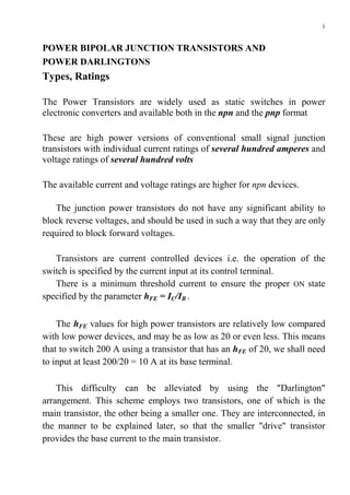
This difficulty can be alleviated by using the "Darlington"
arrangement. This scheme employs two transistors, one of which is the
main transistor, the other being a smaller one. They are interconnected, in
the manner to be explained later, so that the smaller "drive" transistor
provides the base current to the main transistor.
2. 2
The hFE values Darlington circuit is hFEd = hFEA hFEM
Junction Structure, Static Characteristics
The junction structure of a double diffused npn power transistor.
The starting material is an n-type silicon wafer.
First a p layer is formed, by diffusion of impurities, on one side.
A second diffusion, after masking the base terminal area, creates an n
zone, which is the emitter layer.
In some power transistors, an additional low resistivity n region
labeled the n+ layer is formed on top of the collector layer to provide a low
resistance ohmic contact between the collector and the collector metal
layer with good mechanical properties.
3. 3
When a transistor is used as a controlled switch, the control current
input is provided at the base terminal. The control circuit is connected
between the base and emitter. The power terminals of the switch are the
collector and the emitter.
Figure. NPN bipolar junction power transistor.
The output characteristic is a plot of the current Ic through the switch
versus the voltage VCE across it for a fixed value of the current Iв.
Let us assume that V = 150 V, R = 30 Ω and decide to keep Iв at 0.6
A. The voltage VCE across the switch and the current Ic through it must be
given by a point on the characteristic for Iв = 0.6 A. To locate this point,
we used a second relationship by a straight line called the "load line."
VCE = V − I C R = 150V − I C ⋅ 30Ω
What will happen if we progressively reduce the base current IB.
IB IC VCE PDIS=VCE IC
0.6 A ≈5A VCE(SAT)≈2.5V 12.5W
0.4 A ≈5A VCE(SAT)≈2.5V 12.5W
0.2 A 3A 60 V 180W
For Iв = 0.2 A, the intersection point gives VCE = 60 V and a current
of 3 A. The transistor is no longer in the saturated ON state. Such a
condition is to be avoided, because, there is excessive power dissipation in
the transistor (180W), which can result in its damage.
4. 4
It is necessary to ensure a saturated ON state, by providing adequate
base drive current, for the safe and satisfactory operation of the switch.
Therefore, the minimum base current to ensure the saturated ON state is
given by IB=IC/hFE where hFE is a parameter specified in the data sheet of
the transistor.
Often it will be advisable to use a somewhat higher value of base
current than that indicated by the above formula, as a safety feature, to
take care of possible increases in Ic above the anticipated value.
Example
The transistor in the circuit has the following data:
VCE(sat) = 1.5V;
hFE=50;
VBE(sat)=1.8V
(a) Determine the minimum value of Vin necessary to ensure a
satisfactory ON state.
(b) Determine the total ON state power dissipation in the switch and its
break up into collector dissipation and base dissipation.
(c) A transient over-voltage spike occurs in this circuit due to external
causes, resulting in V going up from 100 V to 150V for a short interval.
Since the current is limited by Iв, assume that there is no significant
change in Ic. What will be the power dissipation in the device under these
conditions?
Solution
(a) The ON state current is given by [V-VCE(sat)]/R= (100 - 1.5)/5 = 19.7 A
The minimum Iв is given by 19.7/hFE = 19.7/50 = 0.394 A
Vin = 0.394 x 10 +1.8= 5.74V
(b) The collector power dissipation
P1 =Ic VCE(sat)= 19.7 X 1.5 = 29.55 W
The base power dissipation
P2 = IB VBE(sat) = 1.8 X 0.394 = 0.71 W
The total internal power dissipation is given by p1+p2= 30.26 W
5. 5
(c) If Ic is limited to the same value of 19.7 A, because Iв is unchanged
when the voltage goes up to 150 V, the new value of VCE will be
VCE = 150 - (19.7 X 5) = 51.5 V
The new value of collector power dissipation is given by
VCE IC = 51.5 X 19.7 = 1014.55 W
This shows how the internal power dissipation can go up to potentially
destructive levels, because the existing base drive is inadequate to handle
the transient condition.
Proportional drive.
The above example serves to highlight the fact that the minimum base
current drive needed to ensure the saturated ON state of the transistor
switch depends on the ON state current. In practical converters, the ON state
current through the switch may vary according to load conditions.
Therefore, if we employ a fixed base current drive, this should be
sufficient for the highest ON state current to be expected. This implies that
the base will be over-driven whenever the ON state current is less than the
maximum value.
A major disadvantage of over-driving the base is the increase in the
transition time for turn OFF switching. This happens because excessive
base current will cause excessive injection of minority carriers into the
base region of the transistor, from the emitter side. Because of this, the
collector current will persist for a longer time, until the excess minority
carriers are removed, during turn OFF switching. To overcome this
difficulty, circuit designers some times use "proportional drive." In such a
scheme, the base current is automatically increased or decreased according
to the magnitude of the collector current.
6. 6
SAFE OPERATING AREA (SOA)
When a transistor functions in an electrical circuit, we can define its
"operating point" at any given instant of time by means of the voltage VCE
across it and the current Ic through it. Whenever there is a change of VCE
or Ic, or both, the operating point moves to a different location on this
plane. The transition will be along a curve on the Ic versus VCE plane,
whose path will be determined by the instantaneous values of Ic and VCE
during the change. To ensure safe operation of the transistor without
damage to it, all the operating points should be within finite boundaries on
the Ic versus VCE plane during transitions between operating points, which
may occur during switching or for other reasons. This is called the Safe
Operating Area (SOA). The boundaries of the SOA are usually specified
by the manufacturer of the device, for stated conditions of working. Figure
shows a typical safe operating area.
We shall examine the nature of the SOA and the parameters that determine
each of the boundary lines.
7. 7
1 Maximum Voltage—Available Breakdown Limit.
A transistor has a maximum collector-to-emitter voltage VCE(sat) that it
can withstand, above which avalanche breakdown at the collector junction
will occur. This determines the maximum voltage limit P in the SOA in
Fig. 1.22 and the vertical boundary line PU. An indication of the
maximum voltage capability is also provided in the data sheet of the
transistor, by a parameter labeled as the "sustaining voltage" (VCE(sus)).
2. Cut Off And Saturation Boundaries.
Since Normal operation is above the cut-off line PQ and to the right of
the saturation line QR, these two lines constitute two other boundaries of
the SOA.
3. Peak Current Limit.
The lines RS corresponding to the maximum permissible collector
current constitutes another boundary of the SOA.
4. Maximum Power.
Neglecting the small base power dissipation, the total power
dissipation in the transistor is equal to the collector power dissipation
given by p = VCEIC. The maximum permissible value Pmах = VCEIC
constitutes the bounary of the SOA indicated as ST .
5. Second Breakdown.
In addition to the five boundaries of the SOA already described, there
is another one, shown as TU and labeled "second breakdown." This is a
phenomenon that can occur in a junction power transistor when voltage
current and power dissipation are high, but still below the levels indicated
by the limits discussed earlier. If we assume that during the turn OFF
switching transition the collector current is uniformly distributed over the
collector junction area, the power distribution will also be uniform over
this area. If, on the other hand, the current distribution is nonuniform, local
hot spots can occur due to excessive power dissipation, in locations in the
junction area that experience high current densities. A failure of the device
due to such occurrence of local hot spots is described as "second
breakdown."
In the case of avalanche breakdown, the voltage across the device does
not collapse, but stays at the VCE(sus) level. While avalanche breakdown
need not necessarily result in permanent damage, second breakdown
always does.
8. 8
SWITCHING TIMES
Typical waveforms of collector current during turn ON and turn OFF
transitions are shown in Figure. The instants of time marked therein have
the following significance:
t0 the instant at which the turn ON switching is initiated by the arrival of
the base current pulse
t1 the instant at which the collector current has risen to 10% of its final
value
t2 the instant at which /c reaches 90% of its final value
t3 the instant at which turn OFF switching is initiated
t4 the instant at which the collector current has fallen to 90% of its ON
state value
t5 the instant at which the collector current has fallen to 10% of its on
value
The time delays stated in a typical data sheet of the device are defined as
follows:
tR "rise time" = t2 – t1
tS "storage time" = t4 – t3
tF "fall time" = t5 – t4
9. 9
POWER MOSFETS
TYPES, COMPARISON WITH BJT
The power MOSFET is the high power version of the low power metal
oxide semiconductor field effect transistor (MOSFET) with typical ratings of
tens of amperes and hundreds of volts.
Both "n-channel" and "p-channel" devices are being made, but the
former are available in higher ratings because the electrons have a higher
mobility than holes inside the silicon crystal.
Although the working principle of a power MOSFET is the same as
that of its low power version, there are significant differences in the
internal geometry.
IC MOSFETs have a "planar" structure. This means that all the
terminals of the device are on one side of the silicon pellet. Therefore the
internal current flow paths are parallel to the surface of the pellet.
Power MOSFETs have a vertical structure, meaning that the current
flow is across the pellet, between its power terminals, which make contact
on opposite sides of it. This results in lower internal voltage drop and
higher current capability.
A power MOSFET can be used either as a static switch or for analog
operation. The main considerations in the choice between power
MOSFETs and power junction transistors (BJT) are summarized below.
1. In contrast to BJT the power MOSFET is a voltage controlled device,
which requires negligible current in its control terminal to maintain the
ON state.
2. Power MOSFETs have relatively shorter switching times. Therefore
they can be used at higher switching frequencies.
3. The internal junction structure of a power MOSFET is such that there
exists a diode path in the reverse direction across the main terminals of
the switch. Therefore it is, in effect, a parallel combination of two static
switches—a controlled switch for forward current flow and an
uncontrolled diode switch for reverse currents.
4. BJTs generally have lower ON state voltage drop than power
MOSFETs. Therefore they have less static power dissipation.
5. BJTs are available in much higher current and voltage ratings than
power MOSFETs.
10. 10
JUNCTION STRUCTURE
Power MOSFETs are fabricated in the form of arrays. This means that
a single power MOSFET is in reality a parallel combination of thousands
of individual cells, each cell being a MOSFET in itself.
The device has three external terminals, called Drain, Source and
Gate. The control voltage to implement turn ON is applied between the
gate and the source terminals. The direction of forward current flow in an
n-channel device is from the drain to the source, through it.
The junction structure one cell of an n-channel device is shown bellow.
All the cells have a common drain surface. The source (gate) metal
depositions for all the cells are connected in parallel and constitute the
source (gate) terminal of the device.
11. 11
PRINCIPLE OF OPERATION
OFF state: If there is no input on the gate terminal, no current can
flow from drain to source, because the junction between the n drain
region and the p island is reverse biased. The only current that flows is the
reverse leakage current of this junction, which is negligibly small.
ON state: If a positive voltage (higher than some threshold value) is
applied to the gate, the electric field so created pulls electrons from the n+
zone into the p zone immediately near the gate. In this way an n "channel"
is created linking the source n+ region and the drain n region. This n
channel now provides the path for flow of current from drain to source.
Above this threshold, the cross-sectional area of the channel will increase
with increasing VGS.
For a given value of VGS however, there is a limit to the maximum
current that can flow through the channel. If we keep increasing the drain-
to-source voltage VDS in an attempt to increase the current, there will
initially be a steep increase in current. Afterwards, the current will reach a
saturation value current will reach a saturation value IDS.which is limited
by VGS.
FIGURE (a) Output characteristics and (b) safe operating area.
12. 12
Once the saturation value is reached, further increase in VDS will only
cause increased voltage drop across the device and increased power
dissipation in it, without increase in current. These statements are evident
from the output characteristics shown in Fig. (b). These characteristics
show the relationship between the drain current ID, and VDS for different
values of VGS . A power MOSFET, when used as a switch, should be in the
"unsaturated" region of the output characteristic.
In practice, a VGS value of +12 to +15V will be adequate to turn the switch
fully ON, in the case of most power MOSFETs. Power MOSFETs are also
being manufactured that can be turned fully ON by lower positive voltage
levels such as 5V used in TTL logic ICs. These are called logic level
MOSFETs.
The integral reverse diode or the "body diode" of the power
MOSFET.
If the source is made positive with respect to the drain, there is a direct
path for current flow across the junction between the p region and the
drain n¯ region, which becomes forward-biased under this condition.
Therefore the device functions like a power diode in this direction. This
integral antiparallel diode is an advantageous feature for most switching
applications of the power MOSFET.
OUTPUT CHARACTERISTICS
For any value of VGS above the threshold level, initially for low values of
VDS, the device behaves like a resistance, the current increasing linearly
with voltage. The ratio VDS/ID is the total resistance in the ON state, equal to
RDS(ON). The magnitude of RDS(ON) determines the forward voltage drop and
the internal power dissipation in the device, in its ON state, for a drain
current ID. These are given by
v f = I D RDS (ON ) Pdis = I D RDS ( ON )
2
13. 13
SAFE OPERATING AREA (SOA)
A typical safe operating area (SOA) is shown in Figure (b).
The boundaries are set by
(1) the maximum permissible drain current,
(2) the maximum power dissipation and
(3) the maximum drain-to-source voltage.
There is no second breakdown phenomenon in power MOSFETs.
GATE ELECTRODE CAPACITANCE
Since the gate electrode layer is insulated from the pellet by a silicon
dioxide layer, the gate input current in the static ON state may be
considered zero for all practical purposes. But the conducting surface of
the gate layer has appreciable capacitance with the drain electrode metal
layer and also with the source electrode metal layer. These capacitances
cause charging and discharging currents to flow in the gate terminal during
switching, and therefore affect the design of the gate control circuit. Figure
shows the three interelectrode capacitances Cgd, Cgs and Cds,.
Ciss=Cgs+Cgd
Coss=Cds+Cgd
Crss= Cgd
Device data sheets usually specify the capacitances in the following form:
Ciss is the input capacitance of the gate terminal with the source and drain
Coss is the output capacitance measured with the gate tied to source.
Crss is called the reverse transfer capacitance.
An aspect of circuit behavior that is very important in the design of the
gate control circuit is the magnification of Cgd due to the "Miller effect."
14. 14
INSULATED GATE BIPOLAR TRANSISTORS (IGBTs)
IGBT COMPARED WITH POWER MOSFETS AND POWER BJTS
The IGBT has appeared on the scene relatively recently as a successful
static power switch that combines advantages of MOSFET and BJT.
Like the power MOSFET,
• it is a voltage controlled switch,
• its switching control requirements are practically the same as for a
power MOSFET.
• The switching speeds of IGBTs are higher than those of BJTs
•
Like the power BJT,
• Its ON state voltage drop is typically lower than that of a power
MOSFET .
• The IGBT has no integral reverse diode.
• The IGBT has no significant reverse voltaic blocking capability. The
maximum reverse voltage is typically well below 10 V.
IGBTs are manufactured in voltage and current ratings extending well
beyond what are normally available in power MOSFETs - devices with a
voltage lilting of 1200V and current rating of 600 A are available.
The turn ON times are about the same as in MOSFETs. But turn OFF
times are longer. Therefore, the maximum converter switching frequencies
possible with IGBTs are intermediate between BJTs and power
MOSFETs.
15. 15
JUNCTION STRUCTURE, PRINCIPLE OF WORKING
JUNCTION STRUCTURE. Figure shows the junction structure of a
typical IGBT cell. This should be compared with the structure of an n-
channel power MOSFET.
There is only one difference. In the IGBT, there is an additional p+ layer
over the n+ drain layer of the power MOSFET structure. This p+ region
constitutes the "collector" of the IGBT. As in the power MOSFET, the
adjacent n region consists of an n+ and an n¯ region. Comparison with the
power MOSFET structure shows that the emitter's place in the structure is
identical to that of the source in the power MOSFET. This statement
applies also to the "gate," which is the control terminal in both devices.
The switching control voltage for IGBT is applied across the gate
and the emitter, and this controls the switching in exactly the same way as
in the power MOSFET.
PRINCIPLE OF WORKING. The operation of the IGBT is very similar
to that of the power MOSFET. The basic difference is that the resistance
offered by the n region when current flows through the device in its ON
state is very much smaller in the IGBT. This decrease in resistance occurs
because of the injection of holes from the top p+ zone into this n zone. This
effect is called conductivity modulation of the n region. Because of this,
the current ratings go up from five to ten times in a chip of the same area,
compared with a power MOSFET.
16. 16
Figure shows the current flow paths in an IGBT cell when a positive
gate-to-emitter control voltage above the threshold level is applied.
A positive gate voltage greater than the threshold value creates an n
channel. The n channel so created in the IGBT is shown in Fig. (a) This
channel connects the n+ emitter zone of the IGBT to the middle n region.
The top p+ zone, the middle n region and the lower p island constitute a
pnp transistor. The top p+ region, which is the collector of the IGBT,
functions as the emitter of this pnp transistor under the normal circuit
voltage polarities. A circuit model on this basis is drawn in Fig. (b). The p,
n and p regions of the transistor in this model are labeled with appropriate
subscripts to identify them with the corresponding regions in the structure
in Fig. (a). We notice that the middle n region constitutes the base of the
pnp transistor.
Terminal Capacitances, Gate Drive Requirements, Switching Times
The terminal capacitances of the IGBT are specified in the same
manner as was indicated for the power MOSFET but Cgc capacitance for
the IGBT is significantly smaller than Cgd of the MOSFET, this is an
advantage resulting in a reduction of the effective input capacitance seen
by the gate drive circuit.
The gate drive circuits for IGBTs are similar to those for power
MOSFETs.
17. 17
THE THYRISTOR
The thyristor, also known as the silicon controlled rectifier (SCR), was
the first solid state power semiconductor device to be developed to
function as a controlled static switch, with large current and voltage
capability.
Junction Structure, Packaging, Circuit Symbol
The junction structure is shown in Fig. 1.(a). This is a four-layer structure
with three internal junctions shown labeled as J1, J2, and J3. The device
has three terminals. The "anode" (A) and "cathode" (K) are the power
terminals of the switch. Control input is between the "gate" (G) and K.
When a forward voltage (positive voltage polarity at the anode terminal)
exists across the main terminals of the thyristor, a short current pulse
from gate to cathode will "fire" the thyristor, that is, trigger it into the ON
state. Once the thyristor is fired, the gate has no further control over the
current flow through the device. During the subsequent conduction, it
behaves like a diode. It cannot be turned OFF by a reverse current pulse on
the gate.
The two commonly available types of casings in which thyristor pellets are
packaged are shown in Figs. 1(b) and (c).
Figure 1(d) shows the circuit symbol for the thyristor. This is derived from
that for the diode, with the addition of the gate terminal. The gate terminal
location near the cathode is in conformity with the internal geometry and
the fact that the firing control input is always between the gate and the
cathode.
18. 18
Operating States of the Thyristor
The thyristor can exist in one of three alternative states in circuit
operation.
1. Reverse blocking OFF state
2. Forward blocking OFF state.
3. Forward conducting ON state.
It can stay in each of these states without an electrical input being present
on the gate terminal. The gate serves only to implement the transition from
the forward blocking OFF state to the forward conducting ON state.
Figures 2 (a), (b) and (c) show the three operating states of the thyristor.
Figure 2 Operating states of the thyristor switch.
In (a), the source polarity is such as to reverse-bias the thyristor. With such
a polarity, the thyristor can only exist in the OFF state. The reverse
blocking voltage between A and К is distributed serially across the three
junctions.
In (b), the source voltage polarity is such as to forward-bias the thyristor.
Now J2 is reverse-biased and the thyristor still cannot conduct. We now
have the forward blocking on state. The forward blocking voltage
capability of thyristor is therefore determined by the breakdown limit of
the junction J2. In practical thyristors, the forward blocking voltage rating
is about the same as the reverse blocking voltage rating. The thyristor is a
"symmetrical voltage blocking" device.
19. 19
Turn ON Switching, Two-Transistor Analogy
The turn ON switching of a thyristor is best explained using the "two-
transistor" analogy. Figure 2(a) shows the thyristor junction structure as a
composite of a pnp transistor T1 and an npn transistor T2, by visualizing
an imaginary plane through the pellet as shown by the broken line. For
greater clarity, the two transistors are shown physically separated in (b),
but with the common layers connected together. The thyristor is shown
forward-biased by external source.
In the case of the npn transistor, the cathode layer n; functions as the
emitter. On this basis, the circuit is redrawn in (c) using the appropriate
transistor symbols.
Initially Ig is zero. Both transistors are OFF. If we now send a small gate
current, this serves as the base current Ib2 for the transistor T2. Therefore
a collector current Ic2 results. Inspection of the circuit shows that Ie2
serves as the base current Ib1 for transistor T1. Because of Ib1, a collector
current Ic1 is initiated, Ic1 serves as additional base current for T2,
causing further increase in Ic2. This in turn causes further increase of the
base current of T2 and therefore of Ic1. In this way, a regenerative current
build up process takes place, and both T1 and Т2 drive each other into the
saturated ON state. This happens in a matter of a few microseconds. Once
turned ON, the two transistors mutually supply each other's base current,
and there is no need for an external gate current to maintain the ON state.
The thyristor stays in the ON state with a small forward voltage drop,
which is usually in the neighborhood of 2 V for a high power device.
After turn ON, the gate loses control and it is not possible to implement
turn OFF switching by means of a reverse gate current.
In practical thyristors there is a minimum current necessary to maintain the
device in the ON state. If we decrease V or increase R, the thyristor will
turn OFF when the current tends to fall below this minimum level. The
minimum current necessary to keep the thyristor in the ON state is called
the "holding current." The holding current is lower than the latching
current in practical thyristors.
20. 20
EXAMPLE 1. The thyristor in has a latching current of 300mA. Neglect
forward voltage drop across the thyristor from the instant of
commencement of the gate pulse. Determine the minimum duration of the
gate pulse necessary to ensure turn ON.
Solution. The loop equation for the power circuit from the instant of
commencement of the gate pulse may be written as
di
L = Ri = V
dt
The solution of this equation with (i = 0 at t = 0) will be
i=
V
R
−t
(
1 − e τ = 5 1 − e )
− 20 t
A where τ =
L
R
The gate pulse should be present at least until the current i rises to the
latching level, given as 0.3 A. Therefore
0.3 = 5(1 -е-20t)
This gives the minimum duration of the gate pulse to ensure turn ON as t =
3.094 ms.
EXAMPLE 2 The thyristor in Fig. has a holding current of 150 mA.
When it was turned ON, R was at a low value. Now if R is progressively
increased, at what value of R will the thyristor turn OFF? Neglect ON state
forward drop
Solution. The specified holding current implies that the thyristor will
turn OFF if the current tends to fall below this value of 0.15 A.
Therefore the highest value of R possible with the thyristor ON will be
R = 300/0.15 = 2000 Ω.
21. 21
THE ASYMMETRICAL THYRISTOR
The asymmetrical thyristor, also known us the asymmetrical silicon
controlled rectifier (ASCR) is a modified version of the thyristor. Its turn
OFF time is much shorter. Therefore it can be used for switching at a
higher repetitive frequencies than the ordinary thyristor. The shorter turn
OFF time is made possible at the cost of the ability to block reverse
voltages.
The junction structure is exactly the same pnpn
four-layer structure of the thyristor, with one
difference. The middle n layer now consists of a
low resistivity (high impurity) region labeled as
n+, and the usual high resistivity (low impurity)
region labeled as n¯.
The reason for the long turn OFF time in the conventional thyristor is
that, during the reverse recovery transient, the flow of reverse current
causes holes to be injected across the junction J2 from the p2 to the n1
layer. These holes have to disappear, mainly by recombination, before the
junction J2, winch is the junction responsible for blocking forward
voltages, recovers its Mocking ability. In normal thyristors, this
recombination process takes a longer time because of the high purity level
of the n1 layer. In the asymmetrical thyristor, the presence of the higher
impurity n+ layer speeds up the recombination process and so shortens the
turn OFF time.
.
22. 22
THE GATE TURN OFF THYRISTOR (GTO)
In the conventional thyristor, the gate serves only to implement the turn
ON switching. It has no role to play in the turn OFF switching operation.
But the GTO can be turned ON like a conventional thyristor, and can also
be turned OFF by means of a reverse gate current pulse. The conventional
thyristor has a symmetrical voltage blocking ability, which means that it
has the ability to block forward as well as reverse voltages of
approximately equal magnitude.
There are two types of GTOs—
1. the reverse blocking type, which has symmetrical voltage blocking
capability, and
2. the "anode short" type, which can block only large forward voltages.
The reverse voltage blocking ability of the anode short type of GTO
is very small, typically below 15 V.
In recent years, the GTO has become a popular switching device for high
power applications. At the higher end of the power range, a single GTO of
the anode short type may have a voltage rating of 4500 V and a current
rating of 300 A. The corresponding values for a symmetrical GTO will be
4500 V and 2500 A.
Junction Structures of Symmetrical and Anode Short Types of GTOs
The junction structures of both types of GTOs have evolved from the
conventional thyristor structure
In the conventional thyristor, the major part
of the gate p layer, labeled p2 in the figure,
can be seen to be sandwiched between the
cathode n layer (n2) and the middle n layer
(nl). The gate metallization, which is the
electrical terminal connection to the gate
through which gale current flows into the
gate layer, is limited to a small area of the gate layer, which is labeled as
X. It is physically distant from areas such as Y of the cathode layer.
Therefore, once the Thyristor has been latched into conduction, a reverse
gate current pulse of reasonable amplitude cannot influence the cathode
current in remote regions of the cathode such as Y.
23. 23
In GTO the distance between the gate metallization areas and the cathode
areas is very much reduced. The location on the cathode is in close
proximity to the boundaries of the gate metallization. Therefore, with a
reverse gate current pulse, it is possible to reduce the current through the
gate layer to the level at which the sequence of switching that was initiated
by a positive gate current and resulted in the turn ON switching of the
device can be made to take place in reverse, resulting in the turn OFF
switching.
The turn ON switching was explained by using the two-transistor
equivalent structure of the thyristor in which the two transistors
regeneratively increase each other's base current, when once the gate
current of the npn transistor is initially brought to a high enough level at
which this mutual regenerative current build up can commence.
But, the turn OFF switching is also implemented by lowering the current
through the gate layer by a reverse gate current pulse to a level below
which the two transistors begin to mutually reduce each other's base
current and drive both to the OFF state.
The minimum gate current pulse amplitude to turn ON the device is
independent of the actual ON state current through the device that flows
after turn ON. But the minimum amplitude of the reverse gate current pulse
to successfully turn OFF the device is dependent on the current I to be
turned OFF.
It is given by the following relationship: Ig = I / βoff ,
where βoff is the "turn OFF current gain." The turn OFF current gain of a
GTO is low, and can be typically in the range 4-5. This means that, to turn
OFF a current of 100 A, the minimum reverse current peak has to be in the
range of 20-25 A.
The turn OFF current gain depends also on circuit conditions such as
rate of rise of reverse current. A higher —dig/dt will generally be
associated with a higher turn OFF gain, but may lead to greater power
dissipation.
A consequence of the higher level of interdigitization in a GTO is that,
although a GTO is turned ON by a positive gate current pulse of short
duration, like a conventional thyristor, it also normally needs a continuous
current of small magnitude lasting for the entire duration of the ON state, to
maintain it stably in the ON state.
24. 24
Gate Control Circuit for a GTO
The typical If.itures of a gate control circuit are illustrated by the scheme
shown bellow
This circuit employs two isolated power supplies, labeled PS1 and PS2.
The common point of both the power supplies is connected to the cathode
of GTO. PS1 provides an isolated positive voltage labeled +VGG and PS2
provides an isolated negative voltage labeled +VGG with respect to the
calhode of GTO.
In this scheme, the switching control circuit of the converter, in which the
GTO is used as a switching element, should provide a positive pulse
lasting for the entire duration of the ON period. The instant of initiation of
the turn on switching is the instant labeled t2. The switching control
circuit should provide a positive pulse of short duration, as shown from t2
to t3, by the lower waveform in Figure to implement turn OFF.
This scheme employs optocouplers to isolate the turn ON and turn OFF
pulses. The turn ON pulse sends current through the light-emitting diode of
the optocoupler module labeled OC1. This causes the phototransistor of
this module, labeled Q1, to turn ON. The turn ON of Q1 causes Q1 to turn
ON by providing base current to it. The collector current of Q2 serves as
the positive gate current input to the GTO. Initially, this current has a
larger amplitude, because initially the capacitor С is uncharged and
functions as a short circuit. Therefore the initial current magnitude is
determined by the value of R1, which is low. As the capacitor С gets
25. 25
charged, the current is diverted through R2, which has larger value and
therefore limits the gate current to the low value needed for the rest of the
duration of the ON state.
The turn OFF switching is achieved through the optocoupler ОС2. The turn
OFF switching signal current through the LED of the optocoupler causes
turn ON of its phototransistor, labeled Q3. This turns on Q4 and thereby
Q5. The collector current of Q5 will be determined by its base current
input, which in turn will be determined by the value of the base resistance,
labeled R3. The collector current of Q5 is the reverse gate current that
turns OFF the GTO. In a high power converter, in which the ON state
current through the GTO may be of the order of 1000 A, the magnitude of
the reverse gate current may be several hundred amperes and it may be
necessary to have several individual transistors in parallel to serve as Q5.
In such cases, the negative power supply PS2 may be of higher current
rating than the positive gate supply PS1.
THE TRIAC
The thyristor is a unidirectional device that permits current flow only in
the anode to cathode direction through it. For the controlled switching of
currents in an AC circuit, in which the current flow is bi-directional, we
need to use two thyristors in "antiparallel" as shown in Fig.(a). The
resulting current waveform is shown in Fig. (b), when the switching in
each AC half-period is delayed by an angle labeled α.
This type of switching scheme is widely used for control of AC
heating and lighting loads. The "triac" is a three-terminal power
semiconductor switching device with which such a switching scheme can
be implemented more simply, using a single device. The triac is a bi-
directional device that is functionally equivalent to two thyristors in
antiparallel. However, it has only one gate terminal, and this serves to
switch current in either direction.
26. 26
FIGURE Controlled bi-directional switching in an AC circuit.
The bi-directional current flow feature of the triac is indicated by the
arrows in both directions in the circuit symbol for the device. For this
reason, the power terminals of the device are not called anode and cathode
as in a thyristor. They are given the names "main terminal 1" (MT1) and
"main terminal 2" (MT2). The control terminal is called "gate."
The switching control terminals are the gate and MT1, irrespective of the
direction of the current to be switched through the main terminals.
The triac is a latching device like a thyristor, and needs only a short pulse
to latch into the ON state. The gate loses control once the device has been
latched into conduction, and it continues to conduct like a diode as long as
the current flow is in the same direction. It turns OFF when the current
tends to reverse, due lo reversal of voltage polarity across the main
terminals.
Although it is more convenient to use a triac instead of two antiparallel
thyristors, the high frequency switching capabilities of triacs are inferior to
those of thyristors. Triacs are seldom used in AC systems of over 400 Hz.
Their most common use is at the power system frequencies of 50 and 60
Hz for the control of low and medium power loads, such as lighting and
heating.