1. armfield
AIR FLOW STUDIES
F6
issue 8
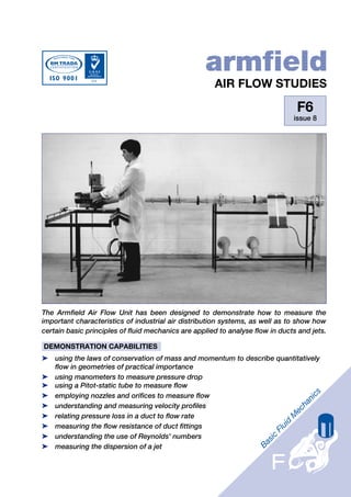
The Armfield Air Flow Unit has been designed to demonstrate how to measure the
important characteristics of industrial air distribution systems, as well as to show how
certain basic principles of fluid mechanics are applied to analyse flow in ducts and jets.
DEMONSTRATION CAPABILITIES
➤ using the laws of conservation of mass and momentum to describe quantitatively
flow in geometries of practical importance
➤ using manometers to measure pressure drop
➤ using a Pitot-static tube to measure flow
➤ employing nozzles and orifices to measure flow
➤ understanding and measuring velocity profiles
➤ relating pressure loss in a duct to flow rate
➤ measuring the flow resistance of duct fittings
➤ understanding the use of Reynolds' numbers
➤ measuring the dispersion of a jet
2. DESCRIPTION
The equipment comprises a long smooth A conventional flow measuring orifice
walled pipe connected to the suction side plate is supplied for installing in the pipe
of an electrically driven centrifugal fan. upstream of the fan for additional
The fan discharge pipe terminates in a demonstrations of pressure loss and
flow control damper for closed conduit recovery.
work or a plate containing a small Air jet studies are carried out on the
aperture for jet dispersion discharge side of the fan. A Pitot tube is
measurements. traversed vertically and horizontally at
Air enters the smooth walled pipe different distances from the discharge
through one of the two flow measurement orifice to investigate the dispersion
nozzles provided. Pressure tappings properties.
along the length of the pipe permit the The equipment is mounted on a floor
pressure gradient to be determined. standing steel frame with an adjacent
A bend or mitred cascade elbow may be support for the extended suction pipe.
fitted at the inlet to the smooth wall pipe Pressure measurements are made on a
for comparison of pressure losses. multi-tube inclinable manometer
Boundary layer growth is determined by mounted on the support frame.
the measurement of the velocity profile at
five stations along the pipe using a
traversing Pitot tube.
Jet
Pitot traverse
Jet traverse
pitot assembly Orifice plate
Alternative bends
& bell mouth
Schematic diagram of Air Flow Unit
3. TECHNICAL DETAILS
Centrifugal fan capacity: 218 l/s at STP
Pipe velocity range: 0-35m/s
Inlet pipe: dia. 80mm
length 2.75m
Interchangeable nozzles: dia. 50mm
and 80mm
Internal pipe orifice: dia. 50mm
Jet discharge pipe orifice: dia. 30mm
Jet traverse range
(downstream LxW): 600mm x 140mm
Manometer range: 0 - 283mm H2O
Manometer fluid: Kerosene
(s.g.0.78)
Pitot tube and discharge orifice
mm
Direction of flow 170
160
150
mm 140
0 130
10
120
20
mm
mm
30 110 100mm m
200m
400
Velocity m/s
300
40 100
40 30 20 10 0
50 90
60
80
70
80 70
Position 1 - 0 60
Position 2 - x 50
Position 3 -
Position 4 - 40
30
Velocity profile in a pipe Jet dispersion at various distances from orifice plate
2534mm
1574mm
774mm
294mm
54mm
5 4 3 2 1
Pipe entrance
Pitot tube position in pipe
4. ORDERING SPECIFICATION ● An instruction manual is supplied that
describes how to perform the airflow
● The unit is self-contained and only experiments and interpret the results, as
requires connection to a single-phase well as how to install, commission and
mains electrical supply. maintain the equipment.
● Turbulence in the 80 mm diameter test
pipe is minimised by locating the pipe at
the inlet of the centrifugal fan.
● A profiled bellmouth inlet prevents air-
separation from the wall of the pipe at the
entrance and straightening vanes
suppress the formation of vortices.
● Tappings along the test pipe allow the
pressure gradient to be measured with air
velocity variable up to a maximum of
35 m/s.
● A Pitot tube can be traversed across the
pipe at five locations to allow boundary
layer growth/development of velocity
profile to be determined.
● Air flowrate is determined from
differential pressure measurements
across an orifice plate or two different
inlet nozzles.
● Different bends and elbows can be fitted
to allow frictional losses in fittings to be A 14-tube manometer board for measuring pressure drops
compared.
● Air jet dispersion experiments are carried COMPLEMENTARY PRODUCTS
out on the discharge side of the fan.
F1: Hydraulics Bench and Accessories
● A Pitot tube can be traversed laterally
F1-301: Computer-aided Learning Programs
(across) and longitudinally (along) the jet
(PC Windows™)
to measure the changes in velocity as the
F5: Osborne Reynolds' Demonstration
jet disperses.
F9092: Fluid Properties & Hydrostatics
● All pressure measurements are performed
Bench
using a bank of fourteen manometer
F10: Cavitation Demonstration
tubes that can be inclined to increase
F12: Particle Drag Coefficients
sensitivity.
F14: Hydrogen Bubble Flow Visualisation
System
SERVICES REQUIRED
Armfield Limited
Electrical supply:
Bridge House West Street Ringwood
F6-A: 220-240V/1ph/50Hz
Hampshire England BH24 1DY
F6-B: 120V/1ph/60Hz
Tel: +44 (0)1425 478781
Fax: +44 (0)1425 470916 OVERALL DIMENSIONS
E mail: sales@armfield.co.uk
URL: http://www.armfield.co.uk Height: 0.7m
Width: 3.8m
USA Office: Depth: 1.9m
Armfield Inc. SHIPPING SPECIFICATION
436 West Commodore Blvd (#2)
Jackson NJ 08527 Volume: 2.3m3
Gross weight: 220kg
Tel: (732) 928-3332
Fax: (732) 928-3542 Specifications may change without notice
E mail: armfield@optonline.net iss8/5k/1203/B&S.