
Empfohlen
Weitere ähnliche Inhalte
Was ist angesagt?
Was ist angesagt? (20)
Ähnlich wie Cam profile
Ähnlich wie Cam profile (20)
Mehr von physics101
Mehr von physics101 (20)
Cam profile
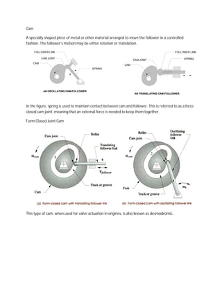
- 1. Cam A specially shaped piece of metal or other material arranged to move the follower in a controlled fashion. The follower’s motion may be either rotation or translation. FOLLOWER LINK FOLLOWER LINK CAM JOINT SPRING CAM JOINT CAM CAM SPRING AN OSCILLATING CAM-FOLLOWER AN TRANSLATING CAM-FOLLOWER In the figure, spring is used to maintain contact between cam and follower. This is referred to as a force closed cam joint, meaning that an external force is needed to keep them together. Form Closed Joint Cam This type of cam, when used for valve actu actuation in engines, is also known as desmodromic.
- 2. Kinematically, cam follower systems are four bar linkages. Classification of Cams: 1. Type of follower motion - Rotating or swinging or oscillating - Translating or sliding 2. Type of joint closure - Forced closure requires an external force to be applied to the joint. Forced closed requires joint can only push, not pull. - Form closure closes the joint by geometry 3. Type of follower
- 3. 4. Follower constraints - Gravity constraints. Weight of follower system is sufficient to maintain contact. - Spring constraints. The spring must be strong enough to maintain contact. - Positive constraints. The groove maintains positive action. 5. Type of cam
- 4. 6. Follower position 7. Type of motion constraints - Critical Extreme Position (CEP) also called end point specification refers to the case in which design specifications define only the start and finish position of the follower, but do not specific any constraints on the path of motion between those extreme positions. - Critical Path Motion (CPM) is a more constrained problem than CEP because the path motion and/or one or more of its derivatives are defined over all or part of the interval motion. 8. Type of motion program - Dwell-rise-dwell cam (DRD). This is the most common type. It has a dwell at the beginning and at the end of the rise. - Dwell-rise-return-dwell cam (DRRD). There is no dwell between the rise and return. - Rise-return-rise cam (RRR). There are no dwells. This type has little applications, as the motion is more adapted to an eccentric.
- 5. Cam Nomenclatures: Trace point: A theoretical point on the follower, corresponding to the point of a fictitious knife- edge follower. It is used to generate the pitch curve. In the case of a roller follower, the trace point is at the center of the roller. Pitch curve: The path generated by the trace point at the follower is rotated about a stationary cam. Working curve: The working surface of a cam in contact with the follower. For the knife-edge follower of the plate cam, the pitch curve and the working curves coincide. In a close or grooved cam there is an inner profile and an outer working curve. Pitch circle: A circle from the cam center through the pitch point. The pitch circle radius is used to calculate a cam of minimum size for a given pressure angle. Prime circle (reference circle): The smallest circle from the cam center through the pitch curve. Base circle: The smallest circle from the cam center through the cam profile curve. Stroke or throw:The greatest distance or angle through which the follower moves or rotates. Follower displacement: The position of the follower from a specific zero or rest position (usually its the position when the f ollower contacts with the base circle of the cam) in relation to time or the rotary angle of the cam. Pressure angle: The angle at any point between the normal to the pitch curve and the instantaneous direction of the follower motion. This angle is important in cam design because it represents the steepness of the cam profile.
- 6. Reference: Cam Design and Manufacturing Handbook 2nd Edition by Robert L. Norton © 2009 by Industrial Press Inc., New York. Cam Design AMCO (Commercial Cam Co., Inc.) by Clyde H. Moon, P.E. Introduction to Mechanism by Yi Zhang with Susan Finger and Stephannie