SlideShare ist ein Scribd-Unternehmen logo
1 von 17
Downloaden Sie, um offline zu lesen
01
Technical paper on major energy saving potential in thermal power plant & effective implementation of EC Act
2001 in Power Sector (Issue#28)By

   Name: Mr. Santosh Mahadeo Mestry
   Designation: Sr. Manager
   Company name: Reliance Energy
   Complete postal address: C-8/5, Reliance Energy staff Qtrs, Dahanu      Thermal power Station, Dahanu Road,
   Thane Pin-401608
   Fax no:       +912528222576
   Email ID: santosh.mestry@relianceada.com,smmestry74@yahoo.com
   User ID: smmestry74
   Mobile Number: 9325119771

                                                         INDEX

    S r.                                      Particulars
    No .

     1      Profile

     2      Energy Saving Potential Areas in Thermal Power Plant

     3      Success Stories (Major ENCON Projects)

     4      Energy management Cell Constitution & Function

     5      Energy Management Policy

     6      Suggestion for effective implementation of EC ACT 2001 in Power sector


     7      Conclusion


                                                      1. Profile


               1.     Power Plant Name                 Reliance Energy Dahanu thermal Power Stn
               2.     Location                         Dahanu
               3.     State/UT                         Maharashtra
               4.     Power Plant Capacity             500 MW

    A.
           Photograph


                                                                                                                 1
B.    Personal Details:
              1. Name :                                  Santosh Mahadeo Mestry
              2. Regd. No. (EM/EA)/ Year of passing:     EM/EA- 4760           Year:2006
              3. Designation:                            Sr. Manager
              4. Qualifications:                         MBA(Finance), BE(Instrumentation)
              5. Email Address:                          Smmestrry74@yahoo.com
              6. Complete postal address                 C-8/5, Staff qtrs, REL colony, Dahanu Road Thane,
             7. Fax No:                                  Maharashtra-401608
                                                         +912528222576

    C.
          Total experience in years Energy               10 years
          Management related experience details          5 years


    D.
          Area of Specialization                         Six Sigma project, Energy audit. ENCON proposal


    E.    Major Achievements                             Implemented various ENCON projects


    F.
          Details of Energy Management Projects          VFD installation in CEP, PA fan. Use of turbo ventilators,
          undertaken, if any                             Coal Optimizer software.


                            2. Major energy saving potential areas in Thermal Power Plant

Thermal power plant is designated sector as per EC act 2001. Most thermal power plant uses 30-40% of energy value of
primary fuels. The remaining 60-70% is lost during generation, transmission and distribution of which major loss is in the
form of heat.
Thermal power consist of various sub cycles / systems like air & flue gas cycle, main steam, feed water & condensate
cycle , fuel & ash cycle, Equipment cooling water (ECW), auxiliary cooling water (ACW) system, Compressed air system,
Electrical auxiliary power & lighting system, HVAC system etc.. There is tremendous scope of energy saving potential in
each system/cycle which is given below.

1. Air & flue gas cycle:-

a. Optimizing excess air ratio: - It reduces FD fan & ID fan loading.

b. Replacement of oversize FD and PA fan: - Many thermal power plants have oversize fan causing huge difference
between design & operating point leads to lower efficiency. Hence fan efficiency can be improved by replacing correct
size of fan. If replacement is not possible, Use of HT VFD for PA & ID fan can be the solution.

c. Attending the air & flue gas leakages: - Leakages in air & flue gas path increases fan loading. Use of Thermo vision
monitoring can be adopted to identify leakages in flue gas path. Air preheater performance is one crucial factor in leakage
contribution. If APH leakage exceeds design value then it requires corrective action.

2. Steam, Feed water and condensate cycle:-

a. BFP scoop operation in three element mode instead of DP mode: - In three element mode throttling losses across
FRS valve reduces leads to reduction in BFP power.


                                                                                                                         2
b. Optimization of level set point in LP & HP heater: - Heater drip level affects TTD & DCA of heater which finally
affect feed water O/L temp. Hence it requires setting of drip level set point correctly.

c. Charging of APRDS from CRH line instead of MS line: -APRDS charging from cold reheat (CRH) is always more
beneficial than
from MS line charging.

d. Isolation of steam line which is not in use: - It is not advisable to keep steam line unnecessary charge if steam is not
utilized since   there energy loss occurred due to radiation. For example deareator extraction can be charged from
turbine Extraction/CRH or from APRDS. In normal running APRDS Extraction is not used so same can be kept isolated.

e. Replacement of BFP cartridge: - BFP draws more current If Cartridge is wore out, causing short circuit of feed water
Flow inside the pump. It affects pump performance. Hence cartridge replacement is necessary.

f. Attending passing recirculation valve of BFP: - BFP Power consumption Increases due to passing of R/C valve. It
requires corrective action.

g. Installation of HT VFD for CEP: - CEP capacity is underutilized and also there is pressure loss occurs across
Deareator level control valve. There is large scope of energy saving which can be accomplished by use of HT VFD for
CEP or impeller trimming.

3. Fuel & ash Cycle:-

a. Optimized ball loading in Ball tube mill: - Excessive ball loading increases mill power. Hence ball loading is to be
Optimized depending upon coal fineness report.

b. Use of Wash Coal or Blending with A- grade coal: - F-grade coal has high ash content. Overall performance can be
improved by using Wash coal or blending of F-grade coal with A- grade coal instead of only using F- grade coal.

c. Avoiding idle running of conveyors & crusher in CHP

d. Use of Dry ash Evacuation instead of WET deashing System: - Dry deashing system consumes less power & also
minimizes waste reduction.

e. Optimize mill maintenance:-Mill corrective/preventive maintenance is to be optimized depending parameter like-
running hrs, mill fineness, bottom ash unburnt particle, degree of reject pipe chocking etc.

4. Electrical & lighting system:-

a. Optimizing Voltage level of distribution transformer: - It is found that Operating voltage level is on higher side than
required causing more losses. It is required to reduce the voltage level by tap changing.

b. Use of Auto star/delta/star converter for under loaded motor
Lighting: - Use of electronic chock instead of conventional use copper Chock, Use of CFL, Replacement of mercury
vapor lamp by metal Halide lamp. Use of timer for area lighting is the methods can be used. Lighting has tremendous
potential of saving.

5. ECW & ACW system:-

a. Isolating ECW supply of standby auxiliaries: - Many times standby coolers are kept charged from ECW side. Also
Standby equipment’s auxiliaries like Lube oil system kept running for reliability. We can isolate Standby cooler from ECW
system & switching of standby auxiliaries, doing trade off between return & reliability.

b. Improving condenser performance by condenser tube cleaning & use of highly efficient debris filter: - Tube
cleaning by bullet shot method increases condenser performance, condenser tube cleaning is necessary which is to be
carried out in overhaul. Also highly advanced debris filter contribute condenser performance.

c. Application of special coating on CW pump impeller: - It improves pump impeller profile condition, increasing pump
performance.
                                                                                                                             3
6. Compressed air system:-

a. Optimizing discharge air pressure by tuning loading/unloading cycle: - It helpful to reduce sp. Power
consumption.

b. Use of heat of compression air dryer instead of electrically heated air dryer: - Heat of compression air dryer use
heat generated in compression cycle, thus reduces sp. Power consumption.

c. Use of screw compressor instead reciprocating compressor: - Sp. Power consumption of screw compressor is
less than reciprocating air compressor leads to reduce aux. power consumption.

7. HVAC system

a. Cooling tower performance improvement

b. Installing absorption refrigeration system instead of vapor compression system

c. Use of wind turbo ventilators instead of conventional motor driven exhauster

                                              3. Success stories (Encon projects)

 3.1. Installation of Fabric Expansion Compensator at Primary, Secondary Air Duct and Furnace-Wind Box Duct


Background

In a coal based power plant PA & FD fans supply primary and secondary air required for combustion. This air is heated in
air pre heater to a temperature of 300°C. The hot secondary air is supplied to the boiler from wind box. The joints of air
preheater with primary and secondary air ducts and joints of the wind box are exposed to high wear and tear and results
in heavy leakage of hot dust laden air. The surroundings become very hot and difficult to work.
O bs e rv ati on s
There were severe ash / hot Air leakages in all four corners from wind box & primary, secondary hot air leakages from
expansion bellows.

Technical & Financial analysis

    1. MS plate of 3 mm thickness welded from inside the wind box to cover the metallic expansion bellow to avoid
       direct contact of hot secondary air.
    2. Fabric expansion bellow provided from outside the wind box to cover metallic expansion bellow.
    3. Fabric expansion bellow provided at APH outlet duct in primary & secondary metallic expansion bellow.


               Fabric Expansion Compensator

                                                                                                                         4
Imp a ct of i mp le me nt a t ion


    1. To reduce respective fan loading.
    2. To reduced the ash accumulation around furnace and APH guide bearing area.
    3. To reduced hot air leakages around furnace and APH guide bearing area.
    4. Cost savings of Rs 112.12 Lakh. Per year for both units.

Simple Pay Back Period: 0.11 Years with 12.34 Lakh Rs. Investment

                                 3.2 Modification in Hopper and Shaft Support Insulator
Ba c kg roun d

In any Thermal Power Plant electrostatic precipitation (ESP) forms an integral part of fly ash collecting system, which
plays a vital role in control of TPM present in the flue gases.

For the smooth functioning of ESP, the heating elements provided at hopper and support & shaft insulators play an
important role. The heater in ESP hoppers are provided to avoid clinker formation of the ash being collected at bottom of
ESP. Whereas the heaters provided at support and shaft insulators are required to maintain the temperature above acid
dew point which lies between 80 to 1150C. If temperature fall below the range as mentioned, there will be continuous
tracking of electrical field over the surface of insulator which will result into the damage of insulator and non-availability of
field for collecting the fly ash.

O bs e rv ati on


                                    Location of thermostat before
                                            modification


                                           Location of thermostat
                                           after modification


There was a frequent problem of the T.B. of the heaters circuit and cables getting burnt. This was observed mainly in the
TBs and cables of the incoming junction boxes. After constant monitoring, it was observed that the heaters remained in
service continuously and
as a result there was a continuous flow of current. Whereas heaters are supposed to be in intermittent duty cycle and
designed for controlled operation through thermostat. The heat generated due to Continuous flow of current in the J.B. did
not get dissipated, resulting into the burning of cable, lugs and the terminal blocks, as JBs were only designed for
controlled operation through thermostat.

Technical & Financial analysis
The reason for none switching off of the heaters was evaluated and it was concluded that due to the wrong positioning of
thermostat, the circuit used to never switch off.

The OEM had provided thermostat in support insulator of HVR transformer duct at a height of 1380 mm above support
insulator heater. The improper sensing of the temperature by thermostat probe kept heaters continuously on. The
temperature recorded were 750C and 1300C at thermostat and heater elevations respectively. Then it was decided to
shift the location of thermostat at near the support insulator whose temperature was actually supposed to be sensed. The
matter was also referred to BHEL (OEM) who also vouched for this modification. Accordingly the thermostat were
removed from its current position and installed near the vicinity of support insulator for efficient control of heater circuit
                                                                                                                               5
Impact of implementation

As a result of modification following results were achieved. The energy consumption drastically fell to about 50 %. As
earlier, the heaters were never to get switch off whereas after modification, the heaters are in service for less than 50% of
time in order to maintain the required temperature.

a) The recurring problem of burning of cable, lugs and TB stopped.
b) Energy consumption by support insulator heaters before modification was 24 KW X [4 passes X 2 units] X 24 Hrs. X
   365 days = 16, 81,920 Units.
c) Energy Consumption after modification. The energy consumption after modification was measured for a month and it
   was found that the consumption reduced to around 50% of its earlier consumption.
   d) Hence financial saving on account of reduced energy consumption @ Rs. 3.50 per unit comes to be Rs.
      30,00,000/- Per annum (Recurring).
Simple Pay Back Period: Immediate with zero investment

                                  3.3 Replacement of Cartridge of Boiler Feed Pump
Ba c kg roun d

One of the major auxiliaries of DTPS is Boiler Feed Pump (9000 KW). The purpose of Boiler Feed Pump is to pump feed
water to boiler drum, provide spray water to HPBP, APRDS, De-super heater station. One BFP caters to entire
requirement of the process. The second pump remains as an auto stand by equipment.

O bs e rv ati on

The Boiler Feed Pump at DTPS is of multistage (three stage) type. It was observed that the BFP-2B is taking much higher
current than other BFPs. From performance curve of the pump also it was clear that it is consuming much higher power
corresponding to the flow.
Technical & Financial analysis
It was concluded that loss is taking place due to interstage leakage or recirculation. Hence decision was taken to replace
the cartridge of pump.


Impact of Implementation

After replacing the cat ridge the current drawn by current reduced by 70 Amp.
Power saved per day= 1.73*6.6*70*.85*24=16304 KWH
Power saved per year=5951290 KWH
Saving of cost= 5951290*3.5=Rs20829515
Simple Pay Back Period: 0.19 Years with 40 Lakh Rs. Investment

                                                                                                                           6
3.4 Drum Level Controlled by BFP SCOOP operation in three Element mode instead of DP mode

Background:

Boiler drum level control is done by BFP scoop & feed water regulating station (FRS) control valve in two ways,
1. DP mode
2. Three element mode,
In DP mode BFP scoop maintain the DP across the FRS as per set point & control valve regulate feed water flow as per
three element errors to maintain drum level as per set point. Whereas in three element mode, scoop maintain the drum
level as per three element error keeping FRS control valve wide open.

Observation:

In most of units having MD BFP only, drum level control is accomplished through DP mode because it believed that is
robust control. But it results in appreciable energy loss due to throttling of FRS valve. DP set point for scoop is observed
between the range of 7-10 kg/cm2; hence same is the pressure drop across FRS valve. Reason of high DP set point to
increase differential pressure to improves the control. Disadvantage of DP mode is increased pressure loss & Energy
loss.

Technical & Financial Analysis:

Energy Saving potential in throttled FRS valve is given below which clearly indicates pump power loss can be optimized
by minimizing pressure drop across the valve.


                                             Pressure drop across the valve x Pump Power        DP optimization in DP
 Energy Saving Potential          =          -------------------------------------------------------
                                                                                                mode        gives     no
                                                  Total Pressure Rise across the Pump           substantial       energy
                                                                                                saving due controlling
action of FRS valve. Further pressure drop reduction is only possible in three element mode scoop operation where FRS
valve is kept fully open.


                                             Pump power (100- efficiency)
       Pump losses % =                       -------------------------------------
                                                 Generated Load

In 250 MW capacity unit having overall efficiency of 38 % and for pump power= 7 MW, DP =7.5 kg/cm2, Total pr.
Developed by pump = 180 kg/cm2, Energy saving potential & Calculated pump loss is given below which are unusually
high figure.
Energy saving potential =29 %
Calculated pump loss = 1.736 % of Boiler Heat I/P
As flow control by throttling in case of high power pump like BFP is inefficient, flow control by speed regulation by means
of BFP scoop is adopted.

Effect on System Curve with Throttling


                                                                                                                          7
HEAD


                                FLOW

In the above system, pump system curve get shifted to lower efficiency region as throttling increases. Point A is the best
efficiency point (BEP) where valve is full open at the pump’s best efficiency point (BEP). But, in actual operation, amount
of flow in valve full open condition is not necessary hence we throttle the valve. To point B to get desired flow. The
reduction in flow rate has to be effected by a throttle valve. In other words, we
are introducing an artificial resistance in the system. Due to this additional resistance, the frictional part of the system
curve increases and thus the new system curve will shift to the left -this is shown as the red curve. So the pump has to
overcome additional pressure in order to deliver the reduced flow. Now, the new system curve will intersect the pump

curve at point B. At point B, pump head is increased the red double

arrow line shows the additional pressure drop due to throttling. You may note that the best efficiency point has shifted
from 82% to 77% efficiency. So what we want is to actually operate at point C which is
on the original system curve for the same required flow. The head required at this point is reduced. What we now need is
a new pump

which will operate with its best efficiency point at C. But there are other simpler options rather than replacing the pump.

The speed of the pump can be reduced or the existing impeller can be trimmed (or new lower size impeller). The blue
pump curve represents either of these options. It is not feasible to replace pump or trimming of impeller, best solution is to
reduce the speed. Hence flow control by speed control method is more efficient.


DP control mode & three element mode schematic is given below.

    1. Scoop operation in DP mode


                                                                                                                              8
2. Scoop operation in three element mode


Changeover philosophy from DP mode to three element mode. (SCOOP Operation- DP mode & Auto. FRS valve- Auto)
   1. Take SCOOP and FRS control Valve in MAN.
   2. Select three element mode of scoop operation.
   3. Put scoop in AUTO. Observe scoop operation.
   4. Gradually open the FRS valve fully.

Changeover philosophy from Three element mode to DP mode. (SCOOP Operation- Three element mode & Auto. FRS
valve- Manual)
    1. Set the required DP set point
    2. Gradually close the FRS valve so that DP across valve matches the DP set point
    3. Take SCOOP in MAN. Select DP mode from three element mode.
    4. Put SCOOP & FRS valve in AUTO. Observe the response.

DP mode is suitable in case of emergency & fluctuating load condition whereas three element mode is suitable in steady
load condition.

Impact of Implementation:

In DTPS, BFP scoop operation successfully tested in three element mode for each BFP.
Pressure drop across FRS valve is observed to be @ 3.5 kg/cm2 in valve full open condition.

                                                                                                                    9
Ampere saving achieve is given below.

                   AMP. Gain/Hr        KW saving/Hr         GHG reduction KG/Hr
1    BFP-1A        10                  97                   83
2    BFP-1B        2.6                 25                   21
3    BFP-2A        4.2                 40                   35
4    BFP-2B        14.2                137                  118

Difference in energy saving may be due to change in vacuum, operating drum pressure & metering error.
BFP hydraulic coupling’s response time and subsequent change in drum level shows that drum level control directly
through BFP scoop operation in three element mode variation is quite feasible especially under steady operating
condition.

Simple Pay Back Period: Immediate with Nil investment

                           3.5 Increased Reliability & Availability Of CW Debris Filter System

Background


At DTPS cooling water used in condenser is seawater. Condenser is two pass once through cooling type. With seawater
floating debris, shells, foreign materials may come and choke the condenser tubes. To avoid choking of condenser tubes
a Debris filter is provided at the inlet of each pass of condenser cooling water inlet. The floating debris, shells, foreign
materials gets filtered in Debris filter screen and gets cleaned by filter online cleaning system which gets started as filter
DP increases.
O bs e rv ati on

Debris filter cleaning system was failing frequently for which there was falling of vacuum in condenser, which led to
generation loss.

Technical & Financial analysis

The following modification has been carried out in the Debris filter system. Modified cleat design of screen basket for firm
fixing with shell.
         Introducing special non-metallic, non-corrosive high wear resistance polymer bearing material in place of
         aluminium Bronze.
         Modified design of gear sealing support to have more rigidity to rotary mechanism
         Introducing smart type debris extraction arm to have excellent debris extraction.
         Introducing one quicker opening manhole at the rear end of the Debris filter shell for easy maintenance.
         Introduction of simplified DP System.
The modified Debris Filter was installed in Unit # I & II during July-August 01 and June-July 02 captive overhaul
respectively. No defects
were raised for U # I from August 2001 to Dec2002. Internal inspection could not be done during the period as Unit was
continuously running. Hence problems had come subsequently after Dec-02.It clearly indicates that the inspection &
repair if any had to be done in every available opportunity. Inspection is not included in PM, as opportunity cannot be
predicted. Secondly every Inspection will cause Generation Loss. The inspection and servicing of Debris filter was done
during unit # I shutdown in Nov-Dec-03 and no defects were raised.
 No defects were raised for U # II after installation of Modified Debris Filter in June-July 02.The Debris filter inspection &
servicing done during unit # II shutdown in Dec-03.

Impact of Implementation

    1. The graph clearly indicates that                                                                        the defects due
       to Debris Filter were reduced                                                                           drastically. This
       has saved partial generation loss,                                                                                 which
       otherwise would have been taken                                                                         up to attend the
       Debris filter problem. This has also                                                                    helped         in
       reducing       the   inventory     &                                                                          manpower
       cost.

                                                                                                                             10
2. The cost savings of Rs 33.6 Lakh has been achieved

Simple Pay Back Period: 1.48 Years with 50 Lakh Rs. Investment


                                                 Condenser inlet pressure zero


                           UNIT # I MODIFIED DEBRIS FILTER REPLACED IN JULY-AUGUST-2001
                          20                                                               UNIT # II SERVICING DONE IN DEC-03
    occurance


                                                    UNIT # II MODIFIED DEBRIS FILTER
                                                    REPLACED IN JUNE-JULY-2002
                                                                                                                                UNIT # I
                                                                10             UNIT # I SERVICING DONE IN NOV-DEC-03            UNIT # II
                                   8
                          7
                                   6                  6                                      6
                                             3
                                             0        0         0         0        0         0          0         0
                             1


                                                         2


                                                                                      04
                    0


                                     1

                                              1


                                                                  2

                                                                           2


                                                                                        3
                                                                                       3
                  -0


                                   -0

                                            -0


                                                                -0

                                                                         -0


                                                                                     -0
                          -0


                                                      -0


                                                                                     -0


                                                                                    b-
                ec


                                          ec


                                                                       ec


                                                                                   ec
                           n


                                    l


                                                      n


                                                                l


                                                                                  ov
                                 Ju


                                                             Ju


                                                                                 Fe
                        Ju


                                                   Ju
                D


                                         D


                                                                      D


                                                                                 D
                                                                               N

                                                               year
                                                                      3.6 condenser tube cleaning

BACKGROUND:-

Sea water source used for cooling causes different tube fouling problems that affect heat transfer and life expectancy of
Heat Exchanger and Condenser Tubing in Power Stations. Hence we employ Bullet Cleaning as an effective and efficient
way of cleaning condenser tubes.

Spring loaded tube cleaner (Bullets) are shot through fouled Condenser Tubes using specially designed water guns at 15-
         2
25 kg/cm water pressure. The bullets moving through the tube from one end to the other scrape off the deposits and
corrosion scales. Water from the gun flushes out scraped deposits resulting in a clean inside surface for the tube, ideal for
good heat transfer. Tube cleaners exit at the end of the condensers, hitting a collection screen hung at the other end.
These cleaners are collected, cleaned and used again. Normally a bullet can be used 10 to 15 times.


                                                                                                                                            Tube Cleaning
                                                                                                                                              Procedure

                                           Bullets


                                                                                                                                                        11
Observations:-

Fouled tubes cause reduction in Heat Transfer, leading to deterioration in Condenser Vacuum then rated. During Unit-2
Shutdown condenser tube cleaning was done by above method. The contribution in condenser vacuum due to tube
cleaning is 7 mm Hg, and gain in Heat rate is 7 Kcal/kWh.

Technical and financial analysis:-

Annual coal saving in Tonnes =
(Heat Rate gain * Unit-2 annual generation)
--------------------------------------------------------
(Avg. GCC of coal *1000)

= (7*2072.689 Lakh kWh)/ (4259*1000) = 340.66 Tonnes.=@340 T

Annual saving in Coal cost = 340 T * 2185.43 Rs/T (Delivered Price) =7.43 Lakh Rs


Impact of Implementation:-
It is summarized in the following table.

                   Improvement                                            Quantity
           Reduction in coal consumption                          By 340 Tonnes per annum
             Total savings in Rs. Lakh                                      7.43
            Total Investment Rs. Lakh                                       3.15
              Simple Payback Period                                      0.42 Years

     Other benefits are:-

     1. TG Heat rate is reduced.
     2. Condensate flow rate is reduced which reduces Condensate extraction pump loading.
     3. CW differential temp. across I/L & O/L of condenser is increased.

                                           3.7 Reduction in steam consumption by fuel switching.

Background:-

Energy conservation can be achieved at fuel oil handling plant terms of steam conservation or electrical energy
conservation or the oil itself. DTPS has been able to achieve major energy saving due to substitution of fuel oil from HFO
to LDO.
Fuel oil system is an important part of a coal based thermal power station, in the absence of which the plant cannot take
off from zero condition.

Observation Made:-

HFO is highly viscous oil, which requires heating to reduce the viscosity up to 15 CST to make it suitable for combustion
in the Boiler. Since the HFO is under constant circulation between the boiler and the fuel oil handling plant, which always
remains at some distant from Boiler, steam tracing lines are used for the heating purpose. The heating medium being
steam, the loss in terms steam energy and condensate through steam traps are quite high.
Looking at the reliability, availability and history of oil consumption
for last few years, it was being decided to stop use of HFO. Since LDO firing system is in place at DTPS, no extra
investment was required.

In case of HFO system, steam is consumed due to

          1.        Steam tracing of HFO lines
          2.        Atomizing
          3.        Heating in heater, Tank and unloading from tanker


                                                                                                                        12
To quantify the losses, measurement of steam consumed for different purpose is done. The details are as follows;

T echn ic al & F in an ci a l An a l ys is M ade: -

Fixed steam consumption

Steam consumed due to condensation in atomizing header = 9.55 T/day (approx.)
Steam consumed due to condensation in steam tracing line= 6.5 T/day (approx.)

Steam consumed in FOPH (Tank heating, line heating, and heater) = 6.5 T/day (approx.)

Variable consumption

Extra steam is consumed during oil firing while raising temperature of oil - 106 kg/ kL of oil fired

The average HFO consumption in previous three financial year was - 150 kL

Steam consumed for heating of oil - 15.90 T

Total steam consumption per day 9.55+6.5+6.50= 22.55 T/day

Total steam consumption per year -22.55*365+ 15.90 = 8246.65t (approx.)

Now if Boiler efficiency =88%, &

Total enthalpy content of steam= 2867 kJ/kg = 686 kcal/kg

Then total heat loss due to steam consumption=686*8246.65*1000

=5657201900 kcal

Calorific value of coal = 4259 kcal/kg

Annual Coal quantity in Tonnes required to produce above steam
          = (5657201900/ (0.88 *4259*1000)) =1509 @ 1500 T.

Coal cost = 1509 T * 2185.43 Rs/T (Delivered Price) =32.97 Lakh Rs.
                                              = @33 Lakh Rs.

Impact of Implementation:-

There is direct saving of 1509 Tonnes of coal per Annum saving in Rs. 33 Lakh.

Simple Pay Back Period: Immediate with Nil investment

Indirect Benefit:-

        Since steam lines for heating of HFO are isolated there is indirect benefit due to reduction in maintenance cost.
        Reliability of oil firing system has increased as LDO is less viscous; the combustion of LDO is less problematic.
        Delay in start up time is avoided.
        Unburnt oil soot deposition in furnace as well as in flue gas ducts, ESP, chimney.
        Reduction in environment pollution in term of Sox (Sulphur percentage in HFO is 4% in comparison to 1.5% in
        LDO)


                                                                                                                      13
3.8 Optimised Ball Loading In Coal Mill

Ba c kg roun d

Coal mills are required in Power Plant for grinding or pulverisation of coal before firing in Furnace. At DTPS we have three
Ball and Tube Mill for each unit. Grinding inside the mill takes place due to impact of alloy steel balls on liners of the Mill
shell and due to friction and attrition.

O bs e rv ati on

In a ball and tube mill for proper grinding certain quantity of balls has to be loaded in mill. The practice at DTPS was to
charge the balls till approximately 160 Amp of current that is drawn by Mill motor at full load. It was observed that due to
ball-to-ball attrition the balls were getting worn out. And after certain running hours certain balls were not taking part in the
grinding process but these balls were increasing the loading of the coal mill.

Technical & Financial analysis
Since the power consumed by mill is very high so to optimise the loading of mill it was decided to reduce the ball charging
in mill so as to reduce loading of mill motor by 10 amps. There was no difference in output and performance of Mill after
reducing ball-charging quantity.

Impact of implementation

Power saved = 1.73*10*6.6*.85*24=2329 KWH
Cost saved per year= 2329*3.5*365=Rs 2975644

Simple Pay Back Period: Immediate with Nil investment

                                Summary of other energy saving measures implemented

( a)      Ret rof itt ing /M inor M odif i c at io ns of e x ist in g e qui pm ent – Low i n v est men t o ptio ns .


Sr. No.        Energy Saving Measures                  Investment             Money saving
                                                       (Rs. Lakhs)            (Rs. Lakhs)
02             Installation of on-line additional      16.00                  250.00
               Oxygen sensors in boiler.
03             Interconnection of U-1 & U-2 chilled    0.20                   28.00
               Water line of centralized air
               conditioning system- to reduce
               power consumption in AC system.
04             Modification in HP heaters.             0.00                   83.00
05             To attend various steam, air, oil,      2.00                   10.00
               ash leakages in day-to-day
               maintenance work.

(b) Replacement/Installation/ Modernization of old and inefficient existing equipment and systems – High
    investment options.
Sr. No.        Energy Saving Measures                  Investment             Money saving
                                                       (Rs. Lakhs)            (Rs. Lakhs)
01             Installation of Variable Frequency      45                     60
               Drive (VFD) in condensate
               extraction Pump.
02             Modernization/ Up gradation of          23.00                  540.00
               Boiler tubes by surface coating with
               High Velocity Oxy Fuel Processes.
03             Replacement of Efficient Purge air      800.00                 3000.00
               Dampers in Milling system.
                                                                                                                              14
( c ) En e rg y sub st it ut i on/ sw it ch ing m e as ur es .
   Sr. No.        Energy Saving Measures                  Investment        Money saving
                                                          (Rs. Lakhs)       (Rs. Lakhs)
   01             Solar Photovoltaic Lighting and         10.00             1.17
                  Solar Water heater.

   (d) Waste Heat Recovery systems (Low Temperature - less than 350/400 C)
   Sr. No.    Energy Saving Measures            Investment           Money saving
                                                (Rs. Lakhs)          (Rs. Lakhs)
   01         Condenser Tube cleaning by Bullet 3. 1 5               800.00
              shot.
   02         To detect air in leakages in      2.70                 1400.00
              condenser by use of Helium based
              air in leakage detector.

       ( e) P ro c es s M onit or ing and Co nt rol s
   Sr. No.       Energy Saving Measures               Investment            Money saving
                                                      (Rs. Lakhs)           (Rs. Lakhs)
   01            Up gradation of ACW controls         05.00                 200.00
   02            Up gradation of ECW controls         05.00                 200.00
   03            Development of PMS initialization    05.00                 20.00
                 floppy’s
   04            Modification of BFP and Mill change 00.00                  61.00
                 over process.

                                                  4. Energy Management Cell

   We have established energy management cell formed as per EC act 2001. EMC structure is given below. It consists of
   cross functional team of certified energy managers & energy auditors.

                                                       4.1 EMC Structure


                                               STATION HEAD


                                                       DGM
                                                      (O & E)


                                                    ENERGY
                                                   MANAGER


                                                   ENERGY
                                                   AUDITOR


MANAGER (C&I)                 MANAGER                           MANAGER              MANAGER
                              (ELECTRICAL)                      (CHP)                (MECHANICAL)


              MANAGER                                                      DEPUTY
              (OPERATIONS)                                                 MANAGER                                15
                                                                           (OPERATIONS)
4.2 EMC Objective
    Objectives of EMC are
       -To operate the power station at highest energy efficiency & optimum cost
       -To create awareness about energy conservation amongst all stakeholders

        EMC achieve objective of “highest energy efficiency and at optimum cost “through following steps.

           Regular internal Energy Audits
           Documentation for energy management activity
           Regular energy audits through accredited energy audit firms
           Regular filling of energy returns to state level designated agency
           Enhancement of employees knowledge through internal training programme
           Energy conservation projects – Identification, Evaluation & Implementation
           Application of energy conservation techniques in the entire gamut of activities of DTPS including purchase,
            Training ,O&M, Inspection & Testing etc.
           Establishing the efficiency test procedures & schedules for all equipments & systems
           MIS

        EMC achieve objective of “Awareness drive” through following initiatives.

           Display of posters and slogans in plant area
           On going sensitization campaign for all employees
           Create awareness among local school children about energy conservation
           Employees suggestion scheme
           Celebration of Energy Conservation week
           Competition of posters & slogans
           Film show
           Display of energy conservation projects
           Technical training sessions from internal & external faculty
           Energy conservation walk involving all employees

                                           4.3 Energy monitoring & targeting

Objectives & targets are set for departmental level as well as individual level. All objectives & target are in line with
corporate strategy & objectives. Everybody is responsible for energy productivity through KRI & KPI. KRA & KPI
dashboards are reviewed on plant level as well as corporate level.
Plant Level Review consist review of Plant performance, Maintenance, Condition monitoring, Generation cost, Heat rate
losses and analysis reports. on Shift basis / Daily / Weekly / Monthly / Half Yearly Calendar year / Financial year basis
       Corporate review macro level in nature & consist of Plant performance, Profitability, Environmental reports
aspects. Not meeting the target is noncompliance product & it is resolved by CA/PA actions.

                                              5. Energy Management Policy
        Reliance Energy Limited is committed to be the most efficient integrated energy utility in the world.
        Our mission is to use all energy resources most efficiently and thereby minimizing the impact of our operations on
        environment and conserving the scarce natural resources.
        This we plan to achieve by,
        Adopting appropriate energy efficient and clean technologies in process design, procurement, implementation and
        also continually upgrade our performance
        Managing efficient use of all forms of energy by adopting industry wide best practices
        Continually benchmarking our energy performance against the best in the world and improving our
        competitiveness by training and knowledge sharing.
        Creating awareness about efficient use of energy and conservation methods amongst all our stakeholders
        Carrying out regular energy audits to identify areas for improvement
        Complying with all relevant state regulatory and statutory requirements on energy management.

                                                                        (Anil D. Ambani)
                                                         Chairman & Managing Director

                                                                                                                        16
Reliance Energy Limited
                      6. Suggestion for effective implementation of EC act 2001 in power sector

Thermal power sector has challenge of meeting growing demand by increasing generation. Bridging of supply & demand
gap is difficult since generation is not increasing with same ratio as demand increases. Generation is lagging behind
supply because thermal power plant is capital intensive & need long lead time for plant construction & modification. Due to
uncertainty in surrounding environment, generation utilities can not develop comprehensive long term capital investment
strategy. If it prepared, it remain on paper most of the time due to uncertain environmental factor like difficulty to get all
clearance. Hence generation addition requires economical, sensible & rational way of business decision approach while
making investment strategy.
As it is known fact that thermal power plant utilizing only 30% of energy value of primary fuel, there is 70% loss mostly in
the form of heat, all generation utilities should be made more responsible for energy productivity. To increase energy
productivity, most essential step is to upgrade generation, transmission & distribution efficiency. As we know that saving
of one electrical unit is equivalent to two units generated, energy conservation plays vital role to bridge the gap between
supply & demand. This is possible by implementing EC act 2001 by reducing auxiliary power consumption we convert
waste unit into salable unit. In fact energy conservation is negative concept, it is more important to talk about energy
efficiency. EC act 2001, take care of both aspect energy conservation & efficiency. Suggestion for effective
implementation of EC act 2001 in power sector is given below.
Top management support: - Energy management programme need total support of top management for success. Top
management should give energy efficiency equal importance in their corporate objective as manpower, raw materials,
production & sales.
Training: - Human capital plays important role in implementation of EC act 2001, training & awareness is necessary to all
employees. A well trained employee can increase energy productivity.
Formation of Energy Management cell (EMC):- It will execute energy management activities across different part of
organization.

Management by objective (MBO):- While setting Key performance indicator (KPI) & Key result area (KRA) energy
conservation & efficiency aspect must be considered. All plant personnel must be involved in energy management
programme. Due to KRA & KPI everybody is responsible for energy productivity and cost effectiveness.

Quality system: - Quality control system like total productive maintenance (TPM), Six sigma, Kaizaen, 5-S, Kanban,
TQM must be adopted by management & need to focus on continuous improvement.

Monitoring & control: - Regular evaluation of energy programme is necessary. Regular monitoring of KPI dashboard will
gives idea of deviation if any. Necessary corrective, preventive action plant is prepared to achieve target.

Adoption of best practices: - Best practice is a process, technique or innovative use of resources & has a proven record
of success in providing significant improvement in performance. Thanks to energymanagertraining.com portal on which no
of success cases are displayed. Website gives concrete examples that demonstrate how to introduce them, shows the
potential payoffs in both qualitative & quantitative terms.

Award & Recognition: - It will motivate the people & increase participation in energy conservation.
Conclusion:-
Thermal power plants contribute 70% of India’s power generation installed capacity. Thermal power plant is designated
sector as per EC ACT-2001. It is not possible to meet the growing demand due to long gestation period of power plant.
Only solution is to reduce auxiliary power consumption by energy conservation & energy efficiency practices. There is
tremendous scope in power sector for reducing auxiliary power consumption (APC) Purpose of EC Act 2001 is same. In
India, It is estimated that; reduction in APC by 1%, equvivalant of generation of 5000 Mu of energy per annum. Saved
energy can be sold out. to minimize the gap between supply & demand. EC act 2001 enable to do energy audit & analysis
& help us to identify number of energy conservation options. To implement EC Act-2001, everybody made responsible for
energy productivity.
EC Act-2001 & Electricity act-2003 has change the scenario of power sector & made it more accountable. This changed
scenario impacted the bottom line of power generation utilities.
Hence the ways to retains one’s competitive edge in the fiercely competitive industry are:-
          Increase in Plant load factor (PLF)
          Improvement in Heat rate
          Improvement in APC
          Reduction in O & M expenditure
          Reduction in distribution losses
          Better cost management.

                                                                                                                           17

Weitere ähnliche Inhalte

Was ist angesagt?

Thermal power plant efficiency
Thermal power plant efficiencyThermal power plant efficiency
Thermal power plant efficiencyManohar Tatwawadi
 
210 MW BHEL Turbine Cycle Heat Balance
210 MW BHEL Turbine Cycle Heat Balance210 MW BHEL Turbine Cycle Heat Balance
210 MW BHEL Turbine Cycle Heat BalanceManohar Tatwawadi
 
210 mw turbine cycle heat rate
210 mw turbine cycle heat rate210 mw turbine cycle heat rate
210 mw turbine cycle heat rateManohar Tatwawadi
 
THERMAL POWER PLANT EFFICIENCY AND HEAT RATE
THERMAL POWER PLANT EFFICIENCY AND HEAT RATETHERMAL POWER PLANT EFFICIENCY AND HEAT RATE
THERMAL POWER PLANT EFFICIENCY AND HEAT RATEManohar Tatwawadi
 
Turbine cycle heat rate calculation
Turbine  cycle heat rate calculationTurbine  cycle heat rate calculation
Turbine cycle heat rate calculationSHIVAJI CHOUDHURY
 
Heat rate of thermal power plant
Heat rate of thermal power plantHeat rate of thermal power plant
Heat rate of thermal power plantManohar Tatwawadi
 
rajwest thermal power plant
rajwest thermal power plantrajwest thermal power plant
rajwest thermal power plantRama Charan
 
27. COGENERATION.ppt
27. COGENERATION.ppt27. COGENERATION.ppt
27. COGENERATION.pptRENERGISTICS
 
Power plant performance_efficiency
Power plant performance_efficiencyPower plant performance_efficiency
Power plant performance_efficiencyKeyur Patel
 
Energy conservation Activites of thermal power plant
Energy conservation Activites of thermal power plantEnergy conservation Activites of thermal power plant
Energy conservation Activites of thermal power plantMANOJ KUMAR MAHARANA
 
Energy audit of Condenser and CW System
Energy audit of Condenser and CW SystemEnergy audit of Condenser and CW System
Energy audit of Condenser and CW SystemManohar Tatwawadi
 
Thermal Power Plant Basic to Knowledge
Thermal Power Plant Basic to KnowledgeThermal Power Plant Basic to Knowledge
Thermal Power Plant Basic to KnowledgeAnshuman Tyagi
 
Hp/ lp bypass system for steam turbines
Hp/ lp bypass system for steam turbinesHp/ lp bypass system for steam turbines
Hp/ lp bypass system for steam turbinesBoben Anto Chemmannoor
 
TPS EFFICIENCY AND HEAT RATE
TPS EFFICIENCY AND HEAT RATE TPS EFFICIENCY AND HEAT RATE
TPS EFFICIENCY AND HEAT RATE Manohar Tatwawadi
 
Large scale energy recovery ppt HRSG
Large scale energy recovery ppt HRSGLarge scale energy recovery ppt HRSG
Large scale energy recovery ppt HRSGlorenzo Monasca
 
01 regenerative feed heating
01 regenerative feed heating01 regenerative feed heating
01 regenerative feed heatingAnil Palamwar
 
Fans in thermal power plants
Fans in thermal power plantsFans in thermal power plants
Fans in thermal power plantsSHIVAJI CHOUDHURY
 
Feedwater heaters in thermal power plants
Feedwater heaters in thermal power plantsFeedwater heaters in thermal power plants
Feedwater heaters in thermal power plantsSHIVAJI CHOUDHURY
 

Was ist angesagt? (20)

Thermal power plant efficiency
Thermal power plant efficiencyThermal power plant efficiency
Thermal power plant efficiency
 
210 MW BHEL Turbine Cycle Heat Balance
210 MW BHEL Turbine Cycle Heat Balance210 MW BHEL Turbine Cycle Heat Balance
210 MW BHEL Turbine Cycle Heat Balance
 
210 mw turbine cycle heat rate
210 mw turbine cycle heat rate210 mw turbine cycle heat rate
210 mw turbine cycle heat rate
 
THERMAL POWER PLANT EFFICIENCY AND HEAT RATE
THERMAL POWER PLANT EFFICIENCY AND HEAT RATETHERMAL POWER PLANT EFFICIENCY AND HEAT RATE
THERMAL POWER PLANT EFFICIENCY AND HEAT RATE
 
Turbine cycle heat rate calculation
Turbine  cycle heat rate calculationTurbine  cycle heat rate calculation
Turbine cycle heat rate calculation
 
Heat rate of thermal power plant
Heat rate of thermal power plantHeat rate of thermal power plant
Heat rate of thermal power plant
 
Super critical boiler
Super critical boilerSuper critical boiler
Super critical boiler
 
rajwest thermal power plant
rajwest thermal power plantrajwest thermal power plant
rajwest thermal power plant
 
27. COGENERATION.ppt
27. COGENERATION.ppt27. COGENERATION.ppt
27. COGENERATION.ppt
 
Power plant performance_efficiency
Power plant performance_efficiencyPower plant performance_efficiency
Power plant performance_efficiency
 
Energy conservation Activites of thermal power plant
Energy conservation Activites of thermal power plantEnergy conservation Activites of thermal power plant
Energy conservation Activites of thermal power plant
 
Energy audit of Condenser and CW System
Energy audit of Condenser and CW SystemEnergy audit of Condenser and CW System
Energy audit of Condenser and CW System
 
Thermal Power Plant Basic to Knowledge
Thermal Power Plant Basic to KnowledgeThermal Power Plant Basic to Knowledge
Thermal Power Plant Basic to Knowledge
 
Dry heat losses in boiler
Dry heat losses in boilerDry heat losses in boiler
Dry heat losses in boiler
 
Hp/ lp bypass system for steam turbines
Hp/ lp bypass system for steam turbinesHp/ lp bypass system for steam turbines
Hp/ lp bypass system for steam turbines
 
TPS EFFICIENCY AND HEAT RATE
TPS EFFICIENCY AND HEAT RATE TPS EFFICIENCY AND HEAT RATE
TPS EFFICIENCY AND HEAT RATE
 
Large scale energy recovery ppt HRSG
Large scale energy recovery ppt HRSGLarge scale energy recovery ppt HRSG
Large scale energy recovery ppt HRSG
 
01 regenerative feed heating
01 regenerative feed heating01 regenerative feed heating
01 regenerative feed heating
 
Fans in thermal power plants
Fans in thermal power plantsFans in thermal power plants
Fans in thermal power plants
 
Feedwater heaters in thermal power plants
Feedwater heaters in thermal power plantsFeedwater heaters in thermal power plants
Feedwater heaters in thermal power plants
 

Ähnlich wie Energy saving areas in TPP

IRJET- Electric Supercharger
IRJET-  	  Electric SuperchargerIRJET-  	  Electric Supercharger
IRJET- Electric SuperchargerIRJET Journal
 
Improve energy efficiency for distillate hydrotreaters retrofit options hyd...
Improve energy efficiency for distillate hydrotreaters retrofit options   hyd...Improve energy efficiency for distillate hydrotreaters retrofit options   hyd...
Improve energy efficiency for distillate hydrotreaters retrofit options hyd...Bhavesh kanani
 
IRJET- Construction of Fuel Oil Pump House at 1x800mw North Chennai Therm...
IRJET-  	  Construction of Fuel Oil Pump House at 1x800mw North Chennai Therm...IRJET-  	  Construction of Fuel Oil Pump House at 1x800mw North Chennai Therm...
IRJET- Construction of Fuel Oil Pump House at 1x800mw North Chennai Therm...IRJET Journal
 
Thermal Power Plant - Manual
Thermal Power Plant - ManualThermal Power Plant - Manual
Thermal Power Plant - ManualSheel Shah
 
IRJET- Improve the Efficiency of Combined Cycle Power Plant
IRJET- Improve the Efficiency of Combined Cycle Power PlantIRJET- Improve the Efficiency of Combined Cycle Power Plant
IRJET- Improve the Efficiency of Combined Cycle Power PlantIRJET Journal
 
IRJET- Fatigue Life Estimation of Turbine Bypass Valve
IRJET- Fatigue Life Estimation of Turbine Bypass ValveIRJET- Fatigue Life Estimation of Turbine Bypass Valve
IRJET- Fatigue Life Estimation of Turbine Bypass ValveIRJET Journal
 
IRJET- Heat Storing Sand Battery
IRJET- Heat Storing Sand BatteryIRJET- Heat Storing Sand Battery
IRJET- Heat Storing Sand BatteryIRJET Journal
 
thermo piezoelectric power generation from wheel
thermo piezoelectric power generation from wheelthermo piezoelectric power generation from wheel
thermo piezoelectric power generation from wheelashish565656
 
Energy Auditing of Thermal Power plant
Energy Auditing of Thermal Power plantEnergy Auditing of Thermal Power plant
Energy Auditing of Thermal Power plantIRJET Journal
 
Energy Based Analysis of a Thermal Power Station for Energy Efficiency Improv...
Energy Based Analysis of a Thermal Power Station for Energy Efficiency Improv...Energy Based Analysis of a Thermal Power Station for Energy Efficiency Improv...
Energy Based Analysis of a Thermal Power Station for Energy Efficiency Improv...IJMER
 
Analysis of Process Parameters to Improve Power Plant Efficiency
Analysis of Process Parameters to Improve Power Plant EfficiencyAnalysis of Process Parameters to Improve Power Plant Efficiency
Analysis of Process Parameters to Improve Power Plant EfficiencyIOSRJMCE
 
Energy Saving and Water Cooling Facility in an Industry Using Prgrammable Log...
Energy Saving and Water Cooling Facility in an Industry Using Prgrammable Log...Energy Saving and Water Cooling Facility in an Industry Using Prgrammable Log...
Energy Saving and Water Cooling Facility in an Industry Using Prgrammable Log...IJERA Editor
 
rajghat-power-house-new-delhi-training-report
rajghat-power-house-new-delhi-training-reportrajghat-power-house-new-delhi-training-report
rajghat-power-house-new-delhi-training-reportRaj Sharma
 
SOLAR STIRLING ENGINE seminar report
SOLAR STIRLING ENGINE seminar reportSOLAR STIRLING ENGINE seminar report
SOLAR STIRLING ENGINE seminar reportEagle .
 
IRJET- Performance and Evaluation of Aqua Ammonia Air Conditioner System ...
IRJET-  	  Performance and Evaluation of Aqua Ammonia Air Conditioner System ...IRJET-  	  Performance and Evaluation of Aqua Ammonia Air Conditioner System ...
IRJET- Performance and Evaluation of Aqua Ammonia Air Conditioner System ...IRJET Journal
 
Assement of-bag-filter-vs-esp-cpcb
Assement of-bag-filter-vs-esp-cpcbAssement of-bag-filter-vs-esp-cpcb
Assement of-bag-filter-vs-esp-cpcbmkpq pasha
 

Ähnlich wie Energy saving areas in TPP (20)

IRJET- Electric Supercharger
IRJET-  	  Electric SuperchargerIRJET-  	  Electric Supercharger
IRJET- Electric Supercharger
 
Improve energy efficiency for distillate hydrotreaters retrofit options hyd...
Improve energy efficiency for distillate hydrotreaters retrofit options   hyd...Improve energy efficiency for distillate hydrotreaters retrofit options   hyd...
Improve energy efficiency for distillate hydrotreaters retrofit options hyd...
 
report on VTPS
report on VTPSreport on VTPS
report on VTPS
 
IRJET- Construction of Fuel Oil Pump House at 1x800mw North Chennai Therm...
IRJET-  	  Construction of Fuel Oil Pump House at 1x800mw North Chennai Therm...IRJET-  	  Construction of Fuel Oil Pump House at 1x800mw North Chennai Therm...
IRJET- Construction of Fuel Oil Pump House at 1x800mw North Chennai Therm...
 
Thermal Power Plant - Manual
Thermal Power Plant - ManualThermal Power Plant - Manual
Thermal Power Plant - Manual
 
IRJET- Improve the Efficiency of Combined Cycle Power Plant
IRJET- Improve the Efficiency of Combined Cycle Power PlantIRJET- Improve the Efficiency of Combined Cycle Power Plant
IRJET- Improve the Efficiency of Combined Cycle Power Plant
 
IRJET- Fatigue Life Estimation of Turbine Bypass Valve
IRJET- Fatigue Life Estimation of Turbine Bypass ValveIRJET- Fatigue Life Estimation of Turbine Bypass Valve
IRJET- Fatigue Life Estimation of Turbine Bypass Valve
 
IRJET- Heat Storing Sand Battery
IRJET- Heat Storing Sand BatteryIRJET- Heat Storing Sand Battery
IRJET- Heat Storing Sand Battery
 
thermo piezoelectric power generation from wheel
thermo piezoelectric power generation from wheelthermo piezoelectric power generation from wheel
thermo piezoelectric power generation from wheel
 
Energy Auditing of Thermal Power plant
Energy Auditing of Thermal Power plantEnergy Auditing of Thermal Power plant
Energy Auditing of Thermal Power plant
 
Heat rate- pulse rate of power plant
Heat rate-  pulse rate of power plantHeat rate-  pulse rate of power plant
Heat rate- pulse rate of power plant
 
Energy Based Analysis of a Thermal Power Station for Energy Efficiency Improv...
Energy Based Analysis of a Thermal Power Station for Energy Efficiency Improv...Energy Based Analysis of a Thermal Power Station for Energy Efficiency Improv...
Energy Based Analysis of a Thermal Power Station for Energy Efficiency Improv...
 
C5693028319.pdf
C5693028319.pdfC5693028319.pdf
C5693028319.pdf
 
Analysis of Process Parameters to Improve Power Plant Efficiency
Analysis of Process Parameters to Improve Power Plant EfficiencyAnalysis of Process Parameters to Improve Power Plant Efficiency
Analysis of Process Parameters to Improve Power Plant Efficiency
 
Energy Saving and Water Cooling Facility in an Industry Using Prgrammable Log...
Energy Saving and Water Cooling Facility in an Industry Using Prgrammable Log...Energy Saving and Water Cooling Facility in an Industry Using Prgrammable Log...
Energy Saving and Water Cooling Facility in an Industry Using Prgrammable Log...
 
rajghat-power-house-new-delhi-training-report
rajghat-power-house-new-delhi-training-reportrajghat-power-house-new-delhi-training-report
rajghat-power-house-new-delhi-training-report
 
[IJET-V1I6P8] Authors: Priyanka Bonde ,R.R.Borase,J.G.Patil
[IJET-V1I6P8] Authors: Priyanka Bonde ,R.R.Borase,J.G.Patil[IJET-V1I6P8] Authors: Priyanka Bonde ,R.R.Borase,J.G.Patil
[IJET-V1I6P8] Authors: Priyanka Bonde ,R.R.Borase,J.G.Patil
 
SOLAR STIRLING ENGINE seminar report
SOLAR STIRLING ENGINE seminar reportSOLAR STIRLING ENGINE seminar report
SOLAR STIRLING ENGINE seminar report
 
IRJET- Performance and Evaluation of Aqua Ammonia Air Conditioner System ...
IRJET-  	  Performance and Evaluation of Aqua Ammonia Air Conditioner System ...IRJET-  	  Performance and Evaluation of Aqua Ammonia Air Conditioner System ...
IRJET- Performance and Evaluation of Aqua Ammonia Air Conditioner System ...
 
Assement of-bag-filter-vs-esp-cpcb
Assement of-bag-filter-vs-esp-cpcbAssement of-bag-filter-vs-esp-cpcb
Assement of-bag-filter-vs-esp-cpcb
 

Kürzlich hochgeladen

Unveiling the Soundscape Music for Psychedelic Experiences
Unveiling the Soundscape Music for Psychedelic ExperiencesUnveiling the Soundscape Music for Psychedelic Experiences
Unveiling the Soundscape Music for Psychedelic ExperiencesDoe Paoro
 
How To Simplify Your Scheduling with AI Calendarfly The Hassle-Free Online Bo...
How To Simplify Your Scheduling with AI Calendarfly The Hassle-Free Online Bo...How To Simplify Your Scheduling with AI Calendarfly The Hassle-Free Online Bo...
How To Simplify Your Scheduling with AI Calendarfly The Hassle-Free Online Bo...SOFTTECHHUB
 
20220816-EthicsGrade_Scorecard-JP_Morgan_Chase-Q2-63_57.pdf
20220816-EthicsGrade_Scorecard-JP_Morgan_Chase-Q2-63_57.pdf20220816-EthicsGrade_Scorecard-JP_Morgan_Chase-Q2-63_57.pdf
20220816-EthicsGrade_Scorecard-JP_Morgan_Chase-Q2-63_57.pdfChris Skinner
 
The-Ethical-issues-ghhhhhhhhjof-Byjus.pptx
The-Ethical-issues-ghhhhhhhhjof-Byjus.pptxThe-Ethical-issues-ghhhhhhhhjof-Byjus.pptx
The-Ethical-issues-ghhhhhhhhjof-Byjus.pptxmbikashkanyari
 
Technical Leaders - Working with the Management Team
Technical Leaders - Working with the Management TeamTechnical Leaders - Working with the Management Team
Technical Leaders - Working with the Management TeamArik Fletcher
 
Jewish Resources in the Family Resource Centre
Jewish Resources in the Family Resource CentreJewish Resources in the Family Resource Centre
Jewish Resources in the Family Resource CentreNZSG
 
The McKinsey 7S Framework: A Holistic Approach to Harmonizing All Parts of th...
The McKinsey 7S Framework: A Holistic Approach to Harmonizing All Parts of th...The McKinsey 7S Framework: A Holistic Approach to Harmonizing All Parts of th...
The McKinsey 7S Framework: A Holistic Approach to Harmonizing All Parts of th...Operational Excellence Consulting
 
trending-flavors-and-ingredients-in-salty-snacks-us-2024_Redacted-V2.pdf
trending-flavors-and-ingredients-in-salty-snacks-us-2024_Redacted-V2.pdftrending-flavors-and-ingredients-in-salty-snacks-us-2024_Redacted-V2.pdf
trending-flavors-and-ingredients-in-salty-snacks-us-2024_Redacted-V2.pdfMintel Group
 
digital marketing , introduction of digital marketing
digital marketing , introduction of digital marketingdigital marketing , introduction of digital marketing
digital marketing , introduction of digital marketingrajputmeenakshi733
 
Cyber Security Training in Office Environment
Cyber Security Training in Office EnvironmentCyber Security Training in Office Environment
Cyber Security Training in Office Environmentelijahj01012
 
Appkodes Tinder Clone Script with Customisable Solutions.pptx
Appkodes Tinder Clone Script with Customisable Solutions.pptxAppkodes Tinder Clone Script with Customisable Solutions.pptx
Appkodes Tinder Clone Script with Customisable Solutions.pptxappkodes
 
Darshan Hiranandani [News About Next CEO].pdf
Darshan Hiranandani [News About Next CEO].pdfDarshan Hiranandani [News About Next CEO].pdf
Darshan Hiranandani [News About Next CEO].pdfShashank Mehta
 
WSMM Technology February.March Newsletter_vF.pdf
WSMM Technology February.March Newsletter_vF.pdfWSMM Technology February.March Newsletter_vF.pdf
WSMM Technology February.March Newsletter_vF.pdfJamesConcepcion7
 
Strategic Project Finance Essentials: A Project Manager’s Guide to Financial ...
Strategic Project Finance Essentials: A Project Manager’s Guide to Financial ...Strategic Project Finance Essentials: A Project Manager’s Guide to Financial ...
Strategic Project Finance Essentials: A Project Manager’s Guide to Financial ...Aggregage
 
WSMM Media and Entertainment Feb_March_Final.pdf
WSMM Media and Entertainment Feb_March_Final.pdfWSMM Media and Entertainment Feb_March_Final.pdf
WSMM Media and Entertainment Feb_March_Final.pdfJamesConcepcion7
 
Effective Strategies for Maximizing Your Profit When Selling Gold Jewelry
Effective Strategies for Maximizing Your Profit When Selling Gold JewelryEffective Strategies for Maximizing Your Profit When Selling Gold Jewelry
Effective Strategies for Maximizing Your Profit When Selling Gold JewelryWhittensFineJewelry1
 
PSCC - Capability Statement Presentation
PSCC - Capability Statement PresentationPSCC - Capability Statement Presentation
PSCC - Capability Statement PresentationAnamaria Contreras
 
Healthcare Feb. & Mar. Healthcare Newsletter
Healthcare Feb. & Mar. Healthcare NewsletterHealthcare Feb. & Mar. Healthcare Newsletter
Healthcare Feb. & Mar. Healthcare NewsletterJamesConcepcion7
 
Church Building Grants To Assist With New Construction, Additions, And Restor...
Church Building Grants To Assist With New Construction, Additions, And Restor...Church Building Grants To Assist With New Construction, Additions, And Restor...
Church Building Grants To Assist With New Construction, Additions, And Restor...Americas Got Grants
 

Kürzlich hochgeladen (20)

Unveiling the Soundscape Music for Psychedelic Experiences
Unveiling the Soundscape Music for Psychedelic ExperiencesUnveiling the Soundscape Music for Psychedelic Experiences
Unveiling the Soundscape Music for Psychedelic Experiences
 
How To Simplify Your Scheduling with AI Calendarfly The Hassle-Free Online Bo...
How To Simplify Your Scheduling with AI Calendarfly The Hassle-Free Online Bo...How To Simplify Your Scheduling with AI Calendarfly The Hassle-Free Online Bo...
How To Simplify Your Scheduling with AI Calendarfly The Hassle-Free Online Bo...
 
20220816-EthicsGrade_Scorecard-JP_Morgan_Chase-Q2-63_57.pdf
20220816-EthicsGrade_Scorecard-JP_Morgan_Chase-Q2-63_57.pdf20220816-EthicsGrade_Scorecard-JP_Morgan_Chase-Q2-63_57.pdf
20220816-EthicsGrade_Scorecard-JP_Morgan_Chase-Q2-63_57.pdf
 
The-Ethical-issues-ghhhhhhhhjof-Byjus.pptx
The-Ethical-issues-ghhhhhhhhjof-Byjus.pptxThe-Ethical-issues-ghhhhhhhhjof-Byjus.pptx
The-Ethical-issues-ghhhhhhhhjof-Byjus.pptx
 
Technical Leaders - Working with the Management Team
Technical Leaders - Working with the Management TeamTechnical Leaders - Working with the Management Team
Technical Leaders - Working with the Management Team
 
Jewish Resources in the Family Resource Centre
Jewish Resources in the Family Resource CentreJewish Resources in the Family Resource Centre
Jewish Resources in the Family Resource Centre
 
The Bizz Quiz-E-Summit-E-Cell-IITPatna.pptx
The Bizz Quiz-E-Summit-E-Cell-IITPatna.pptxThe Bizz Quiz-E-Summit-E-Cell-IITPatna.pptx
The Bizz Quiz-E-Summit-E-Cell-IITPatna.pptx
 
The McKinsey 7S Framework: A Holistic Approach to Harmonizing All Parts of th...
The McKinsey 7S Framework: A Holistic Approach to Harmonizing All Parts of th...The McKinsey 7S Framework: A Holistic Approach to Harmonizing All Parts of th...
The McKinsey 7S Framework: A Holistic Approach to Harmonizing All Parts of th...
 
trending-flavors-and-ingredients-in-salty-snacks-us-2024_Redacted-V2.pdf
trending-flavors-and-ingredients-in-salty-snacks-us-2024_Redacted-V2.pdftrending-flavors-and-ingredients-in-salty-snacks-us-2024_Redacted-V2.pdf
trending-flavors-and-ingredients-in-salty-snacks-us-2024_Redacted-V2.pdf
 
digital marketing , introduction of digital marketing
digital marketing , introduction of digital marketingdigital marketing , introduction of digital marketing
digital marketing , introduction of digital marketing
 
Cyber Security Training in Office Environment
Cyber Security Training in Office EnvironmentCyber Security Training in Office Environment
Cyber Security Training in Office Environment
 
Appkodes Tinder Clone Script with Customisable Solutions.pptx
Appkodes Tinder Clone Script with Customisable Solutions.pptxAppkodes Tinder Clone Script with Customisable Solutions.pptx
Appkodes Tinder Clone Script with Customisable Solutions.pptx
 
Darshan Hiranandani [News About Next CEO].pdf
Darshan Hiranandani [News About Next CEO].pdfDarshan Hiranandani [News About Next CEO].pdf
Darshan Hiranandani [News About Next CEO].pdf
 
WSMM Technology February.March Newsletter_vF.pdf
WSMM Technology February.March Newsletter_vF.pdfWSMM Technology February.March Newsletter_vF.pdf
WSMM Technology February.March Newsletter_vF.pdf
 
Strategic Project Finance Essentials: A Project Manager’s Guide to Financial ...
Strategic Project Finance Essentials: A Project Manager’s Guide to Financial ...Strategic Project Finance Essentials: A Project Manager’s Guide to Financial ...
Strategic Project Finance Essentials: A Project Manager’s Guide to Financial ...
 
WSMM Media and Entertainment Feb_March_Final.pdf
WSMM Media and Entertainment Feb_March_Final.pdfWSMM Media and Entertainment Feb_March_Final.pdf
WSMM Media and Entertainment Feb_March_Final.pdf
 
Effective Strategies for Maximizing Your Profit When Selling Gold Jewelry
Effective Strategies for Maximizing Your Profit When Selling Gold JewelryEffective Strategies for Maximizing Your Profit When Selling Gold Jewelry
Effective Strategies for Maximizing Your Profit When Selling Gold Jewelry
 
PSCC - Capability Statement Presentation
PSCC - Capability Statement PresentationPSCC - Capability Statement Presentation
PSCC - Capability Statement Presentation
 
Healthcare Feb. & Mar. Healthcare Newsletter
Healthcare Feb. & Mar. Healthcare NewsletterHealthcare Feb. & Mar. Healthcare Newsletter
Healthcare Feb. & Mar. Healthcare Newsletter
 
Church Building Grants To Assist With New Construction, Additions, And Restor...
Church Building Grants To Assist With New Construction, Additions, And Restor...Church Building Grants To Assist With New Construction, Additions, And Restor...
Church Building Grants To Assist With New Construction, Additions, And Restor...
 

Energy saving areas in TPP

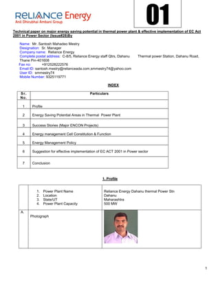
  • 1. 01 Technical paper on major energy saving potential in thermal power plant & effective implementation of EC Act 2001 in Power Sector (Issue#28)By Name: Mr. Santosh Mahadeo Mestry Designation: Sr. Manager Company name: Reliance Energy Complete postal address: C-8/5, Reliance Energy staff Qtrs, Dahanu Thermal power Station, Dahanu Road, Thane Pin-401608 Fax no: +912528222576 Email ID: santosh.mestry@relianceada.com,smmestry74@yahoo.com User ID: smmestry74 Mobile Number: 9325119771 INDEX S r. Particulars No . 1 Profile 2 Energy Saving Potential Areas in Thermal Power Plant 3 Success Stories (Major ENCON Projects) 4 Energy management Cell Constitution & Function 5 Energy Management Policy 6 Suggestion for effective implementation of EC ACT 2001 in Power sector 7 Conclusion 1. Profile 1. Power Plant Name Reliance Energy Dahanu thermal Power Stn 2. Location Dahanu 3. State/UT Maharashtra 4. Power Plant Capacity 500 MW A. Photograph 1
  • 2. B. Personal Details: 1. Name : Santosh Mahadeo Mestry 2. Regd. No. (EM/EA)/ Year of passing: EM/EA- 4760 Year:2006 3. Designation: Sr. Manager 4. Qualifications: MBA(Finance), BE(Instrumentation) 5. Email Address: Smmestrry74@yahoo.com 6. Complete postal address C-8/5, Staff qtrs, REL colony, Dahanu Road Thane, 7. Fax No: Maharashtra-401608 +912528222576 C. Total experience in years Energy 10 years Management related experience details 5 years D. Area of Specialization Six Sigma project, Energy audit. ENCON proposal E. Major Achievements Implemented various ENCON projects F. Details of Energy Management Projects VFD installation in CEP, PA fan. Use of turbo ventilators, undertaken, if any Coal Optimizer software. 2. Major energy saving potential areas in Thermal Power Plant Thermal power plant is designated sector as per EC act 2001. Most thermal power plant uses 30-40% of energy value of primary fuels. The remaining 60-70% is lost during generation, transmission and distribution of which major loss is in the form of heat. Thermal power consist of various sub cycles / systems like air & flue gas cycle, main steam, feed water & condensate cycle , fuel & ash cycle, Equipment cooling water (ECW), auxiliary cooling water (ACW) system, Compressed air system, Electrical auxiliary power & lighting system, HVAC system etc.. There is tremendous scope of energy saving potential in each system/cycle which is given below. 1. Air & flue gas cycle:- a. Optimizing excess air ratio: - It reduces FD fan & ID fan loading. b. Replacement of oversize FD and PA fan: - Many thermal power plants have oversize fan causing huge difference between design & operating point leads to lower efficiency. Hence fan efficiency can be improved by replacing correct size of fan. If replacement is not possible, Use of HT VFD for PA & ID fan can be the solution. c. Attending the air & flue gas leakages: - Leakages in air & flue gas path increases fan loading. Use of Thermo vision monitoring can be adopted to identify leakages in flue gas path. Air preheater performance is one crucial factor in leakage contribution. If APH leakage exceeds design value then it requires corrective action. 2. Steam, Feed water and condensate cycle:- a. BFP scoop operation in three element mode instead of DP mode: - In three element mode throttling losses across FRS valve reduces leads to reduction in BFP power. 2
  • 3. b. Optimization of level set point in LP & HP heater: - Heater drip level affects TTD & DCA of heater which finally affect feed water O/L temp. Hence it requires setting of drip level set point correctly. c. Charging of APRDS from CRH line instead of MS line: -APRDS charging from cold reheat (CRH) is always more beneficial than from MS line charging. d. Isolation of steam line which is not in use: - It is not advisable to keep steam line unnecessary charge if steam is not utilized since there energy loss occurred due to radiation. For example deareator extraction can be charged from turbine Extraction/CRH or from APRDS. In normal running APRDS Extraction is not used so same can be kept isolated. e. Replacement of BFP cartridge: - BFP draws more current If Cartridge is wore out, causing short circuit of feed water Flow inside the pump. It affects pump performance. Hence cartridge replacement is necessary. f. Attending passing recirculation valve of BFP: - BFP Power consumption Increases due to passing of R/C valve. It requires corrective action. g. Installation of HT VFD for CEP: - CEP capacity is underutilized and also there is pressure loss occurs across Deareator level control valve. There is large scope of energy saving which can be accomplished by use of HT VFD for CEP or impeller trimming. 3. Fuel & ash Cycle:- a. Optimized ball loading in Ball tube mill: - Excessive ball loading increases mill power. Hence ball loading is to be Optimized depending upon coal fineness report. b. Use of Wash Coal or Blending with A- grade coal: - F-grade coal has high ash content. Overall performance can be improved by using Wash coal or blending of F-grade coal with A- grade coal instead of only using F- grade coal. c. Avoiding idle running of conveyors & crusher in CHP d. Use of Dry ash Evacuation instead of WET deashing System: - Dry deashing system consumes less power & also minimizes waste reduction. e. Optimize mill maintenance:-Mill corrective/preventive maintenance is to be optimized depending parameter like- running hrs, mill fineness, bottom ash unburnt particle, degree of reject pipe chocking etc. 4. Electrical & lighting system:- a. Optimizing Voltage level of distribution transformer: - It is found that Operating voltage level is on higher side than required causing more losses. It is required to reduce the voltage level by tap changing. b. Use of Auto star/delta/star converter for under loaded motor Lighting: - Use of electronic chock instead of conventional use copper Chock, Use of CFL, Replacement of mercury vapor lamp by metal Halide lamp. Use of timer for area lighting is the methods can be used. Lighting has tremendous potential of saving. 5. ECW & ACW system:- a. Isolating ECW supply of standby auxiliaries: - Many times standby coolers are kept charged from ECW side. Also Standby equipment’s auxiliaries like Lube oil system kept running for reliability. We can isolate Standby cooler from ECW system & switching of standby auxiliaries, doing trade off between return & reliability. b. Improving condenser performance by condenser tube cleaning & use of highly efficient debris filter: - Tube cleaning by bullet shot method increases condenser performance, condenser tube cleaning is necessary which is to be carried out in overhaul. Also highly advanced debris filter contribute condenser performance. c. Application of special coating on CW pump impeller: - It improves pump impeller profile condition, increasing pump performance. 3
  • 4. 6. Compressed air system:- a. Optimizing discharge air pressure by tuning loading/unloading cycle: - It helpful to reduce sp. Power consumption. b. Use of heat of compression air dryer instead of electrically heated air dryer: - Heat of compression air dryer use heat generated in compression cycle, thus reduces sp. Power consumption. c. Use of screw compressor instead reciprocating compressor: - Sp. Power consumption of screw compressor is less than reciprocating air compressor leads to reduce aux. power consumption. 7. HVAC system a. Cooling tower performance improvement b. Installing absorption refrigeration system instead of vapor compression system c. Use of wind turbo ventilators instead of conventional motor driven exhauster 3. Success stories (Encon projects) 3.1. Installation of Fabric Expansion Compensator at Primary, Secondary Air Duct and Furnace-Wind Box Duct Background In a coal based power plant PA & FD fans supply primary and secondary air required for combustion. This air is heated in air pre heater to a temperature of 300°C. The hot secondary air is supplied to the boiler from wind box. The joints of air preheater with primary and secondary air ducts and joints of the wind box are exposed to high wear and tear and results in heavy leakage of hot dust laden air. The surroundings become very hot and difficult to work. O bs e rv ati on s There were severe ash / hot Air leakages in all four corners from wind box & primary, secondary hot air leakages from expansion bellows. Technical & Financial analysis 1. MS plate of 3 mm thickness welded from inside the wind box to cover the metallic expansion bellow to avoid direct contact of hot secondary air. 2. Fabric expansion bellow provided from outside the wind box to cover metallic expansion bellow. 3. Fabric expansion bellow provided at APH outlet duct in primary & secondary metallic expansion bellow. Fabric Expansion Compensator 4
  • 5. Imp a ct of i mp le me nt a t ion 1. To reduce respective fan loading. 2. To reduced the ash accumulation around furnace and APH guide bearing area. 3. To reduced hot air leakages around furnace and APH guide bearing area. 4. Cost savings of Rs 112.12 Lakh. Per year for both units. Simple Pay Back Period: 0.11 Years with 12.34 Lakh Rs. Investment 3.2 Modification in Hopper and Shaft Support Insulator Ba c kg roun d In any Thermal Power Plant electrostatic precipitation (ESP) forms an integral part of fly ash collecting system, which plays a vital role in control of TPM present in the flue gases. For the smooth functioning of ESP, the heating elements provided at hopper and support & shaft insulators play an important role. The heater in ESP hoppers are provided to avoid clinker formation of the ash being collected at bottom of ESP. Whereas the heaters provided at support and shaft insulators are required to maintain the temperature above acid dew point which lies between 80 to 1150C. If temperature fall below the range as mentioned, there will be continuous tracking of electrical field over the surface of insulator which will result into the damage of insulator and non-availability of field for collecting the fly ash. O bs e rv ati on Location of thermostat before modification Location of thermostat after modification There was a frequent problem of the T.B. of the heaters circuit and cables getting burnt. This was observed mainly in the TBs and cables of the incoming junction boxes. After constant monitoring, it was observed that the heaters remained in service continuously and as a result there was a continuous flow of current. Whereas heaters are supposed to be in intermittent duty cycle and designed for controlled operation through thermostat. The heat generated due to Continuous flow of current in the J.B. did not get dissipated, resulting into the burning of cable, lugs and the terminal blocks, as JBs were only designed for controlled operation through thermostat. Technical & Financial analysis The reason for none switching off of the heaters was evaluated and it was concluded that due to the wrong positioning of thermostat, the circuit used to never switch off. The OEM had provided thermostat in support insulator of HVR transformer duct at a height of 1380 mm above support insulator heater. The improper sensing of the temperature by thermostat probe kept heaters continuously on. The temperature recorded were 750C and 1300C at thermostat and heater elevations respectively. Then it was decided to shift the location of thermostat at near the support insulator whose temperature was actually supposed to be sensed. The matter was also referred to BHEL (OEM) who also vouched for this modification. Accordingly the thermostat were removed from its current position and installed near the vicinity of support insulator for efficient control of heater circuit 5
  • 6. Impact of implementation As a result of modification following results were achieved. The energy consumption drastically fell to about 50 %. As earlier, the heaters were never to get switch off whereas after modification, the heaters are in service for less than 50% of time in order to maintain the required temperature. a) The recurring problem of burning of cable, lugs and TB stopped. b) Energy consumption by support insulator heaters before modification was 24 KW X [4 passes X 2 units] X 24 Hrs. X 365 days = 16, 81,920 Units. c) Energy Consumption after modification. The energy consumption after modification was measured for a month and it was found that the consumption reduced to around 50% of its earlier consumption. d) Hence financial saving on account of reduced energy consumption @ Rs. 3.50 per unit comes to be Rs. 30,00,000/- Per annum (Recurring). Simple Pay Back Period: Immediate with zero investment 3.3 Replacement of Cartridge of Boiler Feed Pump Ba c kg roun d One of the major auxiliaries of DTPS is Boiler Feed Pump (9000 KW). The purpose of Boiler Feed Pump is to pump feed water to boiler drum, provide spray water to HPBP, APRDS, De-super heater station. One BFP caters to entire requirement of the process. The second pump remains as an auto stand by equipment. O bs e rv ati on The Boiler Feed Pump at DTPS is of multistage (three stage) type. It was observed that the BFP-2B is taking much higher current than other BFPs. From performance curve of the pump also it was clear that it is consuming much higher power corresponding to the flow. Technical & Financial analysis It was concluded that loss is taking place due to interstage leakage or recirculation. Hence decision was taken to replace the cartridge of pump. Impact of Implementation After replacing the cat ridge the current drawn by current reduced by 70 Amp. Power saved per day= 1.73*6.6*70*.85*24=16304 KWH Power saved per year=5951290 KWH Saving of cost= 5951290*3.5=Rs20829515 Simple Pay Back Period: 0.19 Years with 40 Lakh Rs. Investment 6
  • 7. 3.4 Drum Level Controlled by BFP SCOOP operation in three Element mode instead of DP mode Background: Boiler drum level control is done by BFP scoop & feed water regulating station (FRS) control valve in two ways, 1. DP mode 2. Three element mode, In DP mode BFP scoop maintain the DP across the FRS as per set point & control valve regulate feed water flow as per three element errors to maintain drum level as per set point. Whereas in three element mode, scoop maintain the drum level as per three element error keeping FRS control valve wide open. Observation: In most of units having MD BFP only, drum level control is accomplished through DP mode because it believed that is robust control. But it results in appreciable energy loss due to throttling of FRS valve. DP set point for scoop is observed between the range of 7-10 kg/cm2; hence same is the pressure drop across FRS valve. Reason of high DP set point to increase differential pressure to improves the control. Disadvantage of DP mode is increased pressure loss & Energy loss. Technical & Financial Analysis: Energy Saving potential in throttled FRS valve is given below which clearly indicates pump power loss can be optimized by minimizing pressure drop across the valve. Pressure drop across the valve x Pump Power DP optimization in DP Energy Saving Potential = ------------------------------------------------------- mode gives no Total Pressure Rise across the Pump substantial energy saving due controlling action of FRS valve. Further pressure drop reduction is only possible in three element mode scoop operation where FRS valve is kept fully open. Pump power (100- efficiency) Pump losses % = ------------------------------------- Generated Load In 250 MW capacity unit having overall efficiency of 38 % and for pump power= 7 MW, DP =7.5 kg/cm2, Total pr. Developed by pump = 180 kg/cm2, Energy saving potential & Calculated pump loss is given below which are unusually high figure. Energy saving potential =29 % Calculated pump loss = 1.736 % of Boiler Heat I/P As flow control by throttling in case of high power pump like BFP is inefficient, flow control by speed regulation by means of BFP scoop is adopted. Effect on System Curve with Throttling 7
  • 8. HEAD FLOW In the above system, pump system curve get shifted to lower efficiency region as throttling increases. Point A is the best efficiency point (BEP) where valve is full open at the pump’s best efficiency point (BEP). But, in actual operation, amount of flow in valve full open condition is not necessary hence we throttle the valve. To point B to get desired flow. The reduction in flow rate has to be effected by a throttle valve. In other words, we are introducing an artificial resistance in the system. Due to this additional resistance, the frictional part of the system curve increases and thus the new system curve will shift to the left -this is shown as the red curve. So the pump has to overcome additional pressure in order to deliver the reduced flow. Now, the new system curve will intersect the pump curve at point B. At point B, pump head is increased the red double arrow line shows the additional pressure drop due to throttling. You may note that the best efficiency point has shifted from 82% to 77% efficiency. So what we want is to actually operate at point C which is on the original system curve for the same required flow. The head required at this point is reduced. What we now need is a new pump which will operate with its best efficiency point at C. But there are other simpler options rather than replacing the pump. The speed of the pump can be reduced or the existing impeller can be trimmed (or new lower size impeller). The blue pump curve represents either of these options. It is not feasible to replace pump or trimming of impeller, best solution is to reduce the speed. Hence flow control by speed control method is more efficient. DP control mode & three element mode schematic is given below. 1. Scoop operation in DP mode 8
  • 9. 2. Scoop operation in three element mode Changeover philosophy from DP mode to three element mode. (SCOOP Operation- DP mode & Auto. FRS valve- Auto) 1. Take SCOOP and FRS control Valve in MAN. 2. Select three element mode of scoop operation. 3. Put scoop in AUTO. Observe scoop operation. 4. Gradually open the FRS valve fully. Changeover philosophy from Three element mode to DP mode. (SCOOP Operation- Three element mode & Auto. FRS valve- Manual) 1. Set the required DP set point 2. Gradually close the FRS valve so that DP across valve matches the DP set point 3. Take SCOOP in MAN. Select DP mode from three element mode. 4. Put SCOOP & FRS valve in AUTO. Observe the response. DP mode is suitable in case of emergency & fluctuating load condition whereas three element mode is suitable in steady load condition. Impact of Implementation: In DTPS, BFP scoop operation successfully tested in three element mode for each BFP. Pressure drop across FRS valve is observed to be @ 3.5 kg/cm2 in valve full open condition. 9
  • 10. Ampere saving achieve is given below. AMP. Gain/Hr KW saving/Hr GHG reduction KG/Hr 1 BFP-1A 10 97 83 2 BFP-1B 2.6 25 21 3 BFP-2A 4.2 40 35 4 BFP-2B 14.2 137 118 Difference in energy saving may be due to change in vacuum, operating drum pressure & metering error. BFP hydraulic coupling’s response time and subsequent change in drum level shows that drum level control directly through BFP scoop operation in three element mode variation is quite feasible especially under steady operating condition. Simple Pay Back Period: Immediate with Nil investment 3.5 Increased Reliability & Availability Of CW Debris Filter System Background At DTPS cooling water used in condenser is seawater. Condenser is two pass once through cooling type. With seawater floating debris, shells, foreign materials may come and choke the condenser tubes. To avoid choking of condenser tubes a Debris filter is provided at the inlet of each pass of condenser cooling water inlet. The floating debris, shells, foreign materials gets filtered in Debris filter screen and gets cleaned by filter online cleaning system which gets started as filter DP increases. O bs e rv ati on Debris filter cleaning system was failing frequently for which there was falling of vacuum in condenser, which led to generation loss. Technical & Financial analysis The following modification has been carried out in the Debris filter system. Modified cleat design of screen basket for firm fixing with shell. Introducing special non-metallic, non-corrosive high wear resistance polymer bearing material in place of aluminium Bronze. Modified design of gear sealing support to have more rigidity to rotary mechanism Introducing smart type debris extraction arm to have excellent debris extraction. Introducing one quicker opening manhole at the rear end of the Debris filter shell for easy maintenance. Introduction of simplified DP System. The modified Debris Filter was installed in Unit # I & II during July-August 01 and June-July 02 captive overhaul respectively. No defects were raised for U # I from August 2001 to Dec2002. Internal inspection could not be done during the period as Unit was continuously running. Hence problems had come subsequently after Dec-02.It clearly indicates that the inspection & repair if any had to be done in every available opportunity. Inspection is not included in PM, as opportunity cannot be predicted. Secondly every Inspection will cause Generation Loss. The inspection and servicing of Debris filter was done during unit # I shutdown in Nov-Dec-03 and no defects were raised. No defects were raised for U # II after installation of Modified Debris Filter in June-July 02.The Debris filter inspection & servicing done during unit # II shutdown in Dec-03. Impact of Implementation 1. The graph clearly indicates that the defects due to Debris Filter were reduced drastically. This has saved partial generation loss, which otherwise would have been taken up to attend the Debris filter problem. This has also helped in reducing the inventory & manpower cost. 10
  • 11. 2. The cost savings of Rs 33.6 Lakh has been achieved Simple Pay Back Period: 1.48 Years with 50 Lakh Rs. Investment Condenser inlet pressure zero UNIT # I MODIFIED DEBRIS FILTER REPLACED IN JULY-AUGUST-2001 20 UNIT # II SERVICING DONE IN DEC-03 occurance UNIT # II MODIFIED DEBRIS FILTER REPLACED IN JUNE-JULY-2002 UNIT # I 10 UNIT # I SERVICING DONE IN NOV-DEC-03 UNIT # II 8 7 6 6 6 3 0 0 0 0 0 0 0 0 1 2 04 0 1 1 2 2 3 3 -0 -0 -0 -0 -0 -0 -0 -0 -0 b- ec ec ec ec n l n l ov Ju Ju Fe Ju Ju D D D D N year 3.6 condenser tube cleaning BACKGROUND:- Sea water source used for cooling causes different tube fouling problems that affect heat transfer and life expectancy of Heat Exchanger and Condenser Tubing in Power Stations. Hence we employ Bullet Cleaning as an effective and efficient way of cleaning condenser tubes. Spring loaded tube cleaner (Bullets) are shot through fouled Condenser Tubes using specially designed water guns at 15- 2 25 kg/cm water pressure. The bullets moving through the tube from one end to the other scrape off the deposits and corrosion scales. Water from the gun flushes out scraped deposits resulting in a clean inside surface for the tube, ideal for good heat transfer. Tube cleaners exit at the end of the condensers, hitting a collection screen hung at the other end. These cleaners are collected, cleaned and used again. Normally a bullet can be used 10 to 15 times. Tube Cleaning Procedure Bullets 11
  • 12. Observations:- Fouled tubes cause reduction in Heat Transfer, leading to deterioration in Condenser Vacuum then rated. During Unit-2 Shutdown condenser tube cleaning was done by above method. The contribution in condenser vacuum due to tube cleaning is 7 mm Hg, and gain in Heat rate is 7 Kcal/kWh. Technical and financial analysis:- Annual coal saving in Tonnes = (Heat Rate gain * Unit-2 annual generation) -------------------------------------------------------- (Avg. GCC of coal *1000) = (7*2072.689 Lakh kWh)/ (4259*1000) = 340.66 Tonnes.=@340 T Annual saving in Coal cost = 340 T * 2185.43 Rs/T (Delivered Price) =7.43 Lakh Rs Impact of Implementation:- It is summarized in the following table. Improvement Quantity Reduction in coal consumption By 340 Tonnes per annum Total savings in Rs. Lakh 7.43 Total Investment Rs. Lakh 3.15 Simple Payback Period 0.42 Years Other benefits are:- 1. TG Heat rate is reduced. 2. Condensate flow rate is reduced which reduces Condensate extraction pump loading. 3. CW differential temp. across I/L & O/L of condenser is increased. 3.7 Reduction in steam consumption by fuel switching. Background:- Energy conservation can be achieved at fuel oil handling plant terms of steam conservation or electrical energy conservation or the oil itself. DTPS has been able to achieve major energy saving due to substitution of fuel oil from HFO to LDO. Fuel oil system is an important part of a coal based thermal power station, in the absence of which the plant cannot take off from zero condition. Observation Made:- HFO is highly viscous oil, which requires heating to reduce the viscosity up to 15 CST to make it suitable for combustion in the Boiler. Since the HFO is under constant circulation between the boiler and the fuel oil handling plant, which always remains at some distant from Boiler, steam tracing lines are used for the heating purpose. The heating medium being steam, the loss in terms steam energy and condensate through steam traps are quite high. Looking at the reliability, availability and history of oil consumption for last few years, it was being decided to stop use of HFO. Since LDO firing system is in place at DTPS, no extra investment was required. In case of HFO system, steam is consumed due to 1. Steam tracing of HFO lines 2. Atomizing 3. Heating in heater, Tank and unloading from tanker 12
  • 13. To quantify the losses, measurement of steam consumed for different purpose is done. The details are as follows; T echn ic al & F in an ci a l An a l ys is M ade: - Fixed steam consumption Steam consumed due to condensation in atomizing header = 9.55 T/day (approx.) Steam consumed due to condensation in steam tracing line= 6.5 T/day (approx.) Steam consumed in FOPH (Tank heating, line heating, and heater) = 6.5 T/day (approx.) Variable consumption Extra steam is consumed during oil firing while raising temperature of oil - 106 kg/ kL of oil fired The average HFO consumption in previous three financial year was - 150 kL Steam consumed for heating of oil - 15.90 T Total steam consumption per day 9.55+6.5+6.50= 22.55 T/day Total steam consumption per year -22.55*365+ 15.90 = 8246.65t (approx.) Now if Boiler efficiency =88%, & Total enthalpy content of steam= 2867 kJ/kg = 686 kcal/kg Then total heat loss due to steam consumption=686*8246.65*1000 =5657201900 kcal Calorific value of coal = 4259 kcal/kg Annual Coal quantity in Tonnes required to produce above steam = (5657201900/ (0.88 *4259*1000)) =1509 @ 1500 T. Coal cost = 1509 T * 2185.43 Rs/T (Delivered Price) =32.97 Lakh Rs. = @33 Lakh Rs. Impact of Implementation:- There is direct saving of 1509 Tonnes of coal per Annum saving in Rs. 33 Lakh. Simple Pay Back Period: Immediate with Nil investment Indirect Benefit:- Since steam lines for heating of HFO are isolated there is indirect benefit due to reduction in maintenance cost. Reliability of oil firing system has increased as LDO is less viscous; the combustion of LDO is less problematic. Delay in start up time is avoided. Unburnt oil soot deposition in furnace as well as in flue gas ducts, ESP, chimney. Reduction in environment pollution in term of Sox (Sulphur percentage in HFO is 4% in comparison to 1.5% in LDO) 13
  • 14. 3.8 Optimised Ball Loading In Coal Mill Ba c kg roun d Coal mills are required in Power Plant for grinding or pulverisation of coal before firing in Furnace. At DTPS we have three Ball and Tube Mill for each unit. Grinding inside the mill takes place due to impact of alloy steel balls on liners of the Mill shell and due to friction and attrition. O bs e rv ati on In a ball and tube mill for proper grinding certain quantity of balls has to be loaded in mill. The practice at DTPS was to charge the balls till approximately 160 Amp of current that is drawn by Mill motor at full load. It was observed that due to ball-to-ball attrition the balls were getting worn out. And after certain running hours certain balls were not taking part in the grinding process but these balls were increasing the loading of the coal mill. Technical & Financial analysis Since the power consumed by mill is very high so to optimise the loading of mill it was decided to reduce the ball charging in mill so as to reduce loading of mill motor by 10 amps. There was no difference in output and performance of Mill after reducing ball-charging quantity. Impact of implementation Power saved = 1.73*10*6.6*.85*24=2329 KWH Cost saved per year= 2329*3.5*365=Rs 2975644 Simple Pay Back Period: Immediate with Nil investment Summary of other energy saving measures implemented ( a) Ret rof itt ing /M inor M odif i c at io ns of e x ist in g e qui pm ent – Low i n v est men t o ptio ns . Sr. No. Energy Saving Measures Investment Money saving (Rs. Lakhs) (Rs. Lakhs) 02 Installation of on-line additional 16.00 250.00 Oxygen sensors in boiler. 03 Interconnection of U-1 & U-2 chilled 0.20 28.00 Water line of centralized air conditioning system- to reduce power consumption in AC system. 04 Modification in HP heaters. 0.00 83.00 05 To attend various steam, air, oil, 2.00 10.00 ash leakages in day-to-day maintenance work. (b) Replacement/Installation/ Modernization of old and inefficient existing equipment and systems – High investment options. Sr. No. Energy Saving Measures Investment Money saving (Rs. Lakhs) (Rs. Lakhs) 01 Installation of Variable Frequency 45 60 Drive (VFD) in condensate extraction Pump. 02 Modernization/ Up gradation of 23.00 540.00 Boiler tubes by surface coating with High Velocity Oxy Fuel Processes. 03 Replacement of Efficient Purge air 800.00 3000.00 Dampers in Milling system. 14
  • 15. ( c ) En e rg y sub st it ut i on/ sw it ch ing m e as ur es . Sr. No. Energy Saving Measures Investment Money saving (Rs. Lakhs) (Rs. Lakhs) 01 Solar Photovoltaic Lighting and 10.00 1.17 Solar Water heater. (d) Waste Heat Recovery systems (Low Temperature - less than 350/400 C) Sr. No. Energy Saving Measures Investment Money saving (Rs. Lakhs) (Rs. Lakhs) 01 Condenser Tube cleaning by Bullet 3. 1 5 800.00 shot. 02 To detect air in leakages in 2.70 1400.00 condenser by use of Helium based air in leakage detector. ( e) P ro c es s M onit or ing and Co nt rol s Sr. No. Energy Saving Measures Investment Money saving (Rs. Lakhs) (Rs. Lakhs) 01 Up gradation of ACW controls 05.00 200.00 02 Up gradation of ECW controls 05.00 200.00 03 Development of PMS initialization 05.00 20.00 floppy’s 04 Modification of BFP and Mill change 00.00 61.00 over process. 4. Energy Management Cell We have established energy management cell formed as per EC act 2001. EMC structure is given below. It consists of cross functional team of certified energy managers & energy auditors. 4.1 EMC Structure STATION HEAD DGM (O & E) ENERGY MANAGER ENERGY AUDITOR MANAGER (C&I) MANAGER MANAGER MANAGER (ELECTRICAL) (CHP) (MECHANICAL) MANAGER DEPUTY (OPERATIONS) MANAGER 15 (OPERATIONS)
  • 16. 4.2 EMC Objective Objectives of EMC are -To operate the power station at highest energy efficiency & optimum cost -To create awareness about energy conservation amongst all stakeholders EMC achieve objective of “highest energy efficiency and at optimum cost “through following steps.  Regular internal Energy Audits  Documentation for energy management activity  Regular energy audits through accredited energy audit firms  Regular filling of energy returns to state level designated agency  Enhancement of employees knowledge through internal training programme  Energy conservation projects – Identification, Evaluation & Implementation  Application of energy conservation techniques in the entire gamut of activities of DTPS including purchase, Training ,O&M, Inspection & Testing etc.  Establishing the efficiency test procedures & schedules for all equipments & systems  MIS EMC achieve objective of “Awareness drive” through following initiatives.  Display of posters and slogans in plant area  On going sensitization campaign for all employees  Create awareness among local school children about energy conservation  Employees suggestion scheme  Celebration of Energy Conservation week  Competition of posters & slogans  Film show  Display of energy conservation projects  Technical training sessions from internal & external faculty  Energy conservation walk involving all employees 4.3 Energy monitoring & targeting Objectives & targets are set for departmental level as well as individual level. All objectives & target are in line with corporate strategy & objectives. Everybody is responsible for energy productivity through KRI & KPI. KRA & KPI dashboards are reviewed on plant level as well as corporate level. Plant Level Review consist review of Plant performance, Maintenance, Condition monitoring, Generation cost, Heat rate losses and analysis reports. on Shift basis / Daily / Weekly / Monthly / Half Yearly Calendar year / Financial year basis Corporate review macro level in nature & consist of Plant performance, Profitability, Environmental reports aspects. Not meeting the target is noncompliance product & it is resolved by CA/PA actions. 5. Energy Management Policy Reliance Energy Limited is committed to be the most efficient integrated energy utility in the world. Our mission is to use all energy resources most efficiently and thereby minimizing the impact of our operations on environment and conserving the scarce natural resources. This we plan to achieve by, Adopting appropriate energy efficient and clean technologies in process design, procurement, implementation and also continually upgrade our performance Managing efficient use of all forms of energy by adopting industry wide best practices Continually benchmarking our energy performance against the best in the world and improving our competitiveness by training and knowledge sharing. Creating awareness about efficient use of energy and conservation methods amongst all our stakeholders Carrying out regular energy audits to identify areas for improvement Complying with all relevant state regulatory and statutory requirements on energy management. (Anil D. Ambani) Chairman & Managing Director 16
  • 17. Reliance Energy Limited 6. Suggestion for effective implementation of EC act 2001 in power sector Thermal power sector has challenge of meeting growing demand by increasing generation. Bridging of supply & demand gap is difficult since generation is not increasing with same ratio as demand increases. Generation is lagging behind supply because thermal power plant is capital intensive & need long lead time for plant construction & modification. Due to uncertainty in surrounding environment, generation utilities can not develop comprehensive long term capital investment strategy. If it prepared, it remain on paper most of the time due to uncertain environmental factor like difficulty to get all clearance. Hence generation addition requires economical, sensible & rational way of business decision approach while making investment strategy. As it is known fact that thermal power plant utilizing only 30% of energy value of primary fuel, there is 70% loss mostly in the form of heat, all generation utilities should be made more responsible for energy productivity. To increase energy productivity, most essential step is to upgrade generation, transmission & distribution efficiency. As we know that saving of one electrical unit is equivalent to two units generated, energy conservation plays vital role to bridge the gap between supply & demand. This is possible by implementing EC act 2001 by reducing auxiliary power consumption we convert waste unit into salable unit. In fact energy conservation is negative concept, it is more important to talk about energy efficiency. EC act 2001, take care of both aspect energy conservation & efficiency. Suggestion for effective implementation of EC act 2001 in power sector is given below. Top management support: - Energy management programme need total support of top management for success. Top management should give energy efficiency equal importance in their corporate objective as manpower, raw materials, production & sales. Training: - Human capital plays important role in implementation of EC act 2001, training & awareness is necessary to all employees. A well trained employee can increase energy productivity. Formation of Energy Management cell (EMC):- It will execute energy management activities across different part of organization. Management by objective (MBO):- While setting Key performance indicator (KPI) & Key result area (KRA) energy conservation & efficiency aspect must be considered. All plant personnel must be involved in energy management programme. Due to KRA & KPI everybody is responsible for energy productivity and cost effectiveness. Quality system: - Quality control system like total productive maintenance (TPM), Six sigma, Kaizaen, 5-S, Kanban, TQM must be adopted by management & need to focus on continuous improvement. Monitoring & control: - Regular evaluation of energy programme is necessary. Regular monitoring of KPI dashboard will gives idea of deviation if any. Necessary corrective, preventive action plant is prepared to achieve target. Adoption of best practices: - Best practice is a process, technique or innovative use of resources & has a proven record of success in providing significant improvement in performance. Thanks to energymanagertraining.com portal on which no of success cases are displayed. Website gives concrete examples that demonstrate how to introduce them, shows the potential payoffs in both qualitative & quantitative terms. Award & Recognition: - It will motivate the people & increase participation in energy conservation. Conclusion:- Thermal power plants contribute 70% of India’s power generation installed capacity. Thermal power plant is designated sector as per EC ACT-2001. It is not possible to meet the growing demand due to long gestation period of power plant. Only solution is to reduce auxiliary power consumption by energy conservation & energy efficiency practices. There is tremendous scope in power sector for reducing auxiliary power consumption (APC) Purpose of EC Act 2001 is same. In India, It is estimated that; reduction in APC by 1%, equvivalant of generation of 5000 Mu of energy per annum. Saved energy can be sold out. to minimize the gap between supply & demand. EC act 2001 enable to do energy audit & analysis & help us to identify number of energy conservation options. To implement EC Act-2001, everybody made responsible for energy productivity. EC Act-2001 & Electricity act-2003 has change the scenario of power sector & made it more accountable. This changed scenario impacted the bottom line of power generation utilities. Hence the ways to retains one’s competitive edge in the fiercely competitive industry are:- Increase in Plant load factor (PLF) Improvement in Heat rate Improvement in APC Reduction in O & M expenditure Reduction in distribution losses Better cost management. 17