5. Actuators: EM Actuation BME 601: Superhuman Bionics BME 601: Superhuman Bionics Electromagnetic Force F = (I · dl) × B F is the electromagnetic force on a moving charge I is the current magnitude and dl is the direction of the current B is the magnetic field
6. Actuators: EM Actuation BME 601: Superhuman Bionics BME 601: Superhuman Bionics Electric Motor Theory Brushless Motor
7. BME 601: Superhuman Bionics BME 601: Superhuman Bionics - Linear electromagnetic actuator - Small displacements Actuators: EM Actuation Solenoid Actuator
8. Actuators: EM Actuation BME 601: Superhuman Bionics BME 601: Superhuman Bionics Servo = Electric Motor Reduction Gearbox Displacement Feedback Sensors Shown below, exploded and assembled – ProDigit prosthetic finger made by Touch Bionics using servo technology.
18. BME 601: Superhuman Bionics BME 601: Superhuman Bionics Actuators: Piezoelectric Direct Piezoelectric Effect Stress Voltage Inverse Piezoelectric Effect Voltage Stress
19. Actuators: Piezoelectric BME 601: Superhuman Bionics BME 601: Superhuman Bionics Performance at Different Voltages Piezoelectric Applications: Vibration Damping, Sound Generation/Detection, Small Valves, Scanning Tunneling Electron and Atomic Force Microscopes, etc. Examples of Piezoelectric Materials: Quartz, Cane Sugar, Biological Bone Tissue, Some types of Ceramics, Certain Polymers
30. BME 601: Superhuman Bionics BME 601: Superhuman Bionics Actuators: Contractile Polymer University of Nevada and Environmental Robots, Inc. 2006 Electrochemical Design, Polyacrylonitrile Contractile Fibers Voltage Potential Across Electrodes Electrolysis in NaCl Solution Anode attracts H+ Ions Local pH Gradient Around Polyacrylonitrile
31.
32. BME 601: Superhuman Bionics BME 601: Superhuman Bionics Actuators: Conclusions Actuator Type Typical (Max) Strain (%) Typical (Max) Stress (MPa) Peak Strain rate (%/s) Est. Max Efficiency (%) Relative Speed (full cycle) Relative Strength to Weight Ratio Biological Skeletal Muscle 20(40) 0.1(0.35) >50 ? Medium Very High Electromagnetic Actuators (Solenoid-Motor) 50-N/A 0.1-N/A 1000-200 80-50 Fast-Medium Low Electroactive Polymer Actuators 25(>300) 1(7) >450 60-90 Medium Fast High Piezoelectric Actuators (1.7) (131) >1000 >90 Very Fast Fairly High Air Muscles 20(40) 0.3(1) 200 ? Medium High Contractile Polymer Actuators >40 0.3 <<1 30 Very Slow Low
33. BME 601: Superhuman Bionics BME 601: Superhuman Bionics Actuators: Conclusions Actuator Type Typical (Max) Strain (%) Typical (Max) Stress (MPa) Peak Strain rate (%/s) Est. Max Efficiency (%) Relative Speed (full cycle) Relative Strength to Weight Ratio Biological Skeletal Muscle 20(40) 0.1(0.35) >50 ? Medium Very High Electromagnetic Actuators (Solenoid-Motor) 50-N/A 0.1-N/A 1000-200 80-50 Fast-Medium Low Electroactive Polymer Actuators 25(>300) 1(7) >450 60-90 Medium Fast High Piezoelectric Actuators (1.7) (131) >1000 >90 Very Fast Fairly High Air Muscles 20(40) 0.3(1) 200 ? Medium High Contractile Polymer Actuators >40 0.3 <<1 30 Very Slow Low
34. BME 601: Superhuman Bionics BME 601: Superhuman Bionics Actuators: Conclusions Actuator Type Typical (Max) Strain (%) Typical (Max) Stress (MPa) Peak Strain rate (%/s) Est. Max Efficiency (%) Relative Speed (full cycle) Relative Strength to Weight Ratio Biological Skeletal Muscle 20(40) 0.1(0.35) >50 ? Medium Very High Electromagnetic Actuators (Solenoid-Motor) 50-N/A 0.1-N/A 1000-200 80-50 Fast-Medium Low Electroactive Polymer Actuators 25(>300) 1(7) >450 60-90 Medium Fast High Piezoelectric Actuators (1.7) (131) >1000 >90 Very Fast Fairly High Air Muscles 20(40) 0.3(1) 200 ? Medium High Contractile Polymer Actuators >40 0.3 <<1 30 Very Slow Low
35. BME 601: Superhuman Bionics BME 601: Superhuman Bionics Actuators: Conclusions Actuator Type Typical (Max) Strain (%) Typical (Max) Stress (MPa) Peak Strain rate (%/s) Est. Max Efficiency (%) Relative Speed (full cycle) Relative Strength to Weight Ratio Biological Skeletal Muscle 20(40) 0.1(0.35) >50 ? Medium Very High Electromagnetic Actuators (Solenoid-Motor) 50-N/A 0.1-N/A 1000-200 80-50 Fast-Medium Low Electroactive Polymer Actuators 25(>300) 1(7) >450 60-90 Medium Fast High Piezoelectric Actuators (1.7) (131) >1000 >90 Very Fast Fairly High Air Muscles 20(40) 0.3(1) 200 ? Medium High Contractile Polymer Actuators >40 0.3 <<1 30 Very Slow Low
36. BME 601: Superhuman Bionics BME 601: Superhuman Bionics Actuators: Conclusions Actuator Type Typical (Max) Strain (%) Typical (Max) Stress (MPa) Peak Strain rate (%/s) Est. Max Efficiency (%) Relative Speed (full cycle) Relative Strength to Weight Ratio Biological Skeletal Muscle 20(40) 0.1(0.35) >50 ? Medium Very High Electromagnetic Actuators (Solenoid-Motor) 50-N/A 0.1-N/A 1000-200 80-50 Fast-Medium Low Electroactive Polymer Actuators 25(>300) 1(7) >450 60-90 Medium Fast High Piezoelectric Actuators (1.7) (131) >1000 >90 Very Fast Fairly High Air Muscles 20(40) 0.3(1) 200 ? Medium High Contractile Polymer Actuators >40 0.3 <<1 30 Very Slow Low
37. BME 601: Superhuman Bionics BME 601: Superhuman Bionics Actuators: Conclusions Actuator Type Typical (Max) Strain (%) Typical (Max) Stress (MPa) Peak Strain rate (%/s) Est. Max Efficiency (%) Relative Speed (full cycle) Relative Strength to Weight Ratio Biological Skeletal Muscle 20(40) 0.1(0.35) >50 ? Medium Very High Electromagnetic Actuators (Solenoid-Motor) 50-N/A 0.1-N/A 1000-200 80-50 Fast-Medium Low Electroactive Polymer Actuators 25(>300) 1(7) >450 60-90 Medium Fast High Piezoelectric Actuators (1.7) (131) >1000 >90 Very Fast Fairly High Air Muscles 20(40) 0.3(1) 200 ? Medium High Contractile Polymer Actuators >40 0.3 <<1 30 Very Slow Low
38. BME 601: Superhuman Bionics BME 601: Superhuman Bionics Actuators: Conclusions Actuator Type Typical (Max) Strain (%) Typical (Max) Stress (MPa) Peak Strain rate (%/s) Est. Max Efficiency (%) Relative Speed (full cycle) Relative Strength to Weight Ratio Biological Skeletal Muscle 20(40) 0.1(0.35) >50 ? Medium Very High Electromagnetic Actuators (Solenoid-Motor) 50-N/A 0.1-N/A 1000-200 80-50 Fast-Medium Low Electroactive Polymer Actuators 25(>300) 1(7) >450 60-90 Medium Fast High Piezoelectric Actuators (1.7) (131) >1000 >90 Very Fast Fairly High Air Muscles 20(40) 0.3(1) 200 ? Medium High Contractile Polymer Actuators >40 0.3 <<1 30 Very Slow Low
Hinweis der Redaktion
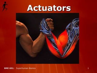
This section of the bionics module will cover different methods of actuation used in prosthetic devices. Actuators are used in any prosthetic device that produces physical motion, such as prosthetic fingers, hands, arms, legs, or even retinal implants. The goal of an actuator in a prosthetic device is to replicate or exceed the function of a biological muscle in the original body part. For example, in the picture shown, the human arm uses its biological actuators known as muscles to arm wrestle, while the robotic arm uses man-made actuators for the same purpose.
In robotics and prosthetics, actuation refers to the process of receiving any type of signal, for example, electrical, chemical, or optical signals (click) , amplifying the signal through a power source (click) , and producing kinetic energy, or physical motion, in response to the signal. An actuator, therefore, is any type of device which accomplishes the process of actuation – for example, your muscles are actuators because they receive brain signals and generate motion accordingly. Actuators may be classified into two types – linear and rotational (click) . A linear actuator will generate force in one direction – (click) your skeletal muscles or hydraulic cylinders are good examples of linear actuators. Rotational actuators generate torque, or rotational force – (click) the electric motor is a common example of a rotational actuator. Rotational motion may be converted to linear motion and vice versa without too much trouble – (click) for example, the piston shown here converts spinning motion into linear motion, while the two muscle-shaped linear actuators are set up antagonistically to generate rotational motion.
For superhuman prosthetics the best actuators will be simple so that risk of failure is low and control is straightforward. (click) The actuator should be able to achieve a wide range of forces and displacements but without loss of fine motor control. (click) The actuators should be able to respond very quickly and (click) must be lightweight to keep power requirements low. Light weight makes the prosthetic more versatile, and reduces wear and fatigue on the user. (click) Finally, the actuator should require as little energy as possible to increase performance time and minimize the extra weight necessitated by power supply.
The first type of actuation we will discuss is electromagnetic actuation, which is currently the most widely used form.
When a charge moves through a magnetic field, it experiences an electromagnetic force proportional to the magnitude of the charge and the magnitude of the magnetic field. The direction of the force vector placed on the moving charge is determined by taking the cross product of the magnetic field direction vector and the direction vector describing the path of the moving charge. If the moving charge is contained in a conductor such as a current-carrying wire, the path of the moving charge is the path of the wire, and the wire carrying the charge is subject to an electromagnetic force when placed in a magnetic field.
In an electric motor, as a battery applies voltage potential across the wire loop, current flows through the loop in one direction. The electromagnetic force F=(I dl) X B is opposite on either side of the wire loop because the current is flowing in opposite directions with respect to the magnetic field. The wire loop is allowed to rotate along its central axis, and the electromagnetic forces on either side of the wire loop form a force couple that generates torque about the central axis, causing the armature to spin. After the wire loop rotates 180 degrees, the torque generated switches directions, causing the armature to experience angular deceleration. To correct for this, electric motors use commutators to switch the polarity of the current in the wire loop every 180 degrees, which keeps the torque vector on the armature pointing in the desired direction. The commutator in this picture uses a split ring and brush system – voltage is applied to the wire loop at the brush contacts, which deliver current to the wire loop through the split ring contacts – every 180 degrees, the brushes come into contact with a different side of the split ring, switching current polarity in the wire loop. (click) The electric motor on the right is a brushless motor, which is typically 10 to 15 percent more efficient than brush motors. The brushless motor uses a different type of commutator to switch current polarity every 180 degrees. The brushless motor shown here has light-emitting diodes on the armature and fixed photo detectors that sense the angular displacement of the armature and use this information to switch current polarity every half rotation. Another type of brushless commutator has a sensor that determines the angular velocity of the armature, and a timer. Using angular velocity and elapsed time, the brushless commutator calculates angular displacement, which is the integral of the angular velocity with respect to time, and uses this information to switch current polarity every half rotation.
Solenoids are linear electromagnetic actuators. The armature is a permanent magnet at the center of a coil of wire – when a current is fed through the wire, it generates a magnetic field that will either attract of repel the armature at the center, depending on the polarity of the current, which will move the armature up or down. Solenoids can achieve only small displacements, and for this reason are used only in special applications where displacements do not need to be large – for example, solenoids are commonly used as valves, such as the one shown in this picture.
In prosthetics, the most commonly used electric motor is a servo motor. Servo motors are electric motors fitted with reduction gearboxes and displacement sensors. The armature of a typical electric motor rotates too fast for use in robotics, so a gearbox is used to reduce the angular velocity of the armature to provide fine motor control. Displacement sensors provide information about what position the armature is in, and send this information back to the controller as feedback. Therefore a servo motor can achieve precise displacements with a wide range of different speeds. (click) The picture here is an example of a prosthetic device using electromagnetic actuation – the ProDigit prosthetic finger from Touch Bionics, for patients who have lost some or all of their fingers. It has a small battery inside which powers the servo motor, and wire connections that receive myoelectric signals from the brain.
The electric motor was invented in the mid-1800’s and has been used extensively in all sorts of applications since then, making it reliable and low-cost. (click) Electromagnetic actuation is inherently bidirectional – meaning the direction of force may be reversed by switching current polarity, and (click) Servos can achieve precise displacements and variable speeds of operation. However, (click) new methods of actuation are being developed that are much more efficient than the electric motor. (click) Power escapes throughout the process of electromagnetic actuation, mostly as heat, and as a result the electric motor is not very energy-efficient. (click) Electric motors also fail to achieve the same strength/weight ratios as other newer actuation techniques due to heavy components, and therefore stand to be replaced in everyday applications.
For the remaining actuation strategies that we will describe in this portion of the module, one key concept to understand is the relationship between stress and strain. Stress is defined as the force applied per unit area of material. Strain is a dimensionless term defined as the change in length of a material when a stress is applied divided by the original length of the material. When stress is applied to a material along a given axis, strain occurs along that same axis.
We now move on to electroactive polymer actuation, a promising new technique that has been researched extensively and is already beginning to replace electric motors in a variety of applications.
Electroactive polymer actuators are constructed out of films of elastic polymer coated with conductive material on both sides of the film. The finished actuator can be thought of as 2 large, but extremely thin, plate electrodes separated by an insulating elastomer film. When a voltage potential is applied across the two electrodes, they acquire opposite charges and attract each other due to induced electrostatic forces. The attraction force between the electrodes places stress on the insulating elastomer film causing it to decrease in thickness and expand in area. The expansion in the x- and y- dimensions can be used to do work.
For an elastic polymer to be effective in an electroactive polymer actuator, it must have certain material properties essential for its functionality. (click) The elastic modulus, also called Young’s modulus, is a measure of the rigidity of the material. It is defined as the ratio between the stress applied to a material and the strain resulting from that stress, and has units of force per area. Elastomers, or rubbers, have low elastic moduli, meaning that for a given stress level, an elastomer will experience higher strains than materials with high elastic moduli. The effect that the elastic modulus has on the actuator’s performance is that a lower elastic modulus will allow the actuator armature to displace farther at a given energy level – however, the farther the armature displaces, the less force the actuator is able to generate - keeping this tradeoff in mind, we can build our actuator with elastomers of different elastic moduli depending on what the actuator will be used for. Another feature the enhances EAP performance is Pre-strain. Pre-Strain is the process of stretching the polymer film before usage, much like you would stretch your leg muscles before going on a run. Pre-strain loosens up the material , modifying the elastic modulus so that the elastomer film will stretch farther and easier. (click) When a material is stressed and lengthens in one dimension, it often results in the decrease of the material in the other dimensions. Conversely, if the material is compressed in one dimension it will expand in the others. You can observe this effect when you pull a rubber band tightly and notice that the band gets progressively thinner as you pull more and more. This is called the Poisson Effect and the relationship between the strain in one axis and its result on the strain in the other axes is called the Poisson Ratio. This ratio is usually between ¼ and ½, meaning a material will contract or expand ¼ to ½ as much as it is pulled or compressed, respectively. Polymers with high Poisson’s Ratios are desirable in EAP because they will produce greater strain parallel to the electrodes when the polymer film is compressed by electrostatic attraction between the electrodes. The dependence of EAP on materials that are both elastomeric and highly conductive presents a challenge. Polymers are highly elastomeric but are well known to be non-conductive. Similarly, metals are highly conductive but are not compliant enough for EAP applications. This mismatch has led to the use of a variety of advanced materials (click) that are compliant enough to stretch with the elastomer film, but also highly conductive, so that they distribute charge quickly and evenly across the film. Examples of effective electrode materials are carbon-impregnated grease, and mixtures of graphite.
(click) The third critical material property is a high dielectric constant. The dielectric constant of the elastomer is another material property critical for maximizing Electroactive Polymer performance and efficiency. When placed between two electrodes, dipoles are induced in the atoms in the dielectric material. This means that one side of the atom acquires a greater electric charge than the other side, and the spherical nature of the electron cloud around the atom becomes elliptic – this is called atomic stretching. When this happens, the atomic dipoles align themselves with the electric field so that the more positive side of the atom is closer to the negative electrode and vice versa. These aligned atoms then attract greater charge onto the surface of the non-conducting polymer film. When a dielectric material is used in a electroactive polymer film, the material itself attracts greater charge onto the electrodes, which then generates a greater attractive force between the electrodes, leading to greater stress across the thickness of the film. An actuator using dielectric material generates greater force by a factor of the dielectric constant of the material, and for this reason, we want to select a material that has a large dielectric constant. (click) The final material property critical for EAP actuation is high ionization energy. Ionization energy is the energy required to knock an electron out of orbit around its respective nucleus – if this value is relatively high, it is more difficult for electrons to flow through a material. If electrons are allowed to flow through our elastomer film, the system short circuits and no force is developed – the greater the voltage applied across the electrodes, the more likely that this will happen. If we use a material with high ionization energy, we can apply a greater voltage across the electrodes and therefore generate greater force without having to worry about short circuiting. (click) A good dielectric elastomer in an electroactive polymer actuator film will have all the material properties we have discussed – relatively low elastic modulus, high poisson’s ratio, high dielectric constant, and high ionization energy – some good examples include certain types of acrylic and certain silicone compounds.
One example of existing EAP actuators is the Universal Muscle Actuator platform from Artificial Muscle, Inc. shown on the left. Two cone-shaped elastomer films are set up antagonistically to provide bidirectional motion when voltage potential is applied across the films. In the animation, when voltage is applied to the film on the left, it expands in area and the armature moves to the right, and vice versa. (click) Other EAP actuators such as the one shown here have designs which more closely resembles the biological muscle. It should be noted that although only two examples are shown, there are many different possible setup methods for EAP actuators.
The electroactive polymer actuator follows one of the main rules of engineering – simplicity. Its simplistic design consists of only the elastomer film and its housing, and operates in direct response to applied voltage. (click) The elastic nature of this design provides built-in shock absorption. (click) Electroactive polymer actuators have very quick response times, and may be operated at a wide range of frequencies. In fact, high frequency operation has led to the use of this technology as a speaker system. (click) The elastomer film is also capable of recovering electric potential as it is returned to its original state after actuation – this increases the energy efficiency of the actuator. (click) Actuators using this technology have been shown to have extremely high strength/weight ratios compared to other actuation methods – an actuator using 2.6 grams of acrylic elastomer film produced 29 N of force at a displacement of 3.5 cm. (click) Pre-strain also increases the energy efficiency and performance of the actuator. (click) Finally, due to the simplicity of the design, electroactive polymer actuation can be anywhere from 25% to 75% cheaper than electromagnetic actuation. (click) The drawbacks of electroactive polymer actuators include the fact that the force they develop decreases with displacement, unlike biological muscle. (click) EAP films only produce linear motion and must be set up antagonistically if rotational motion is required. (click) Finally, the elasticity of the device decreases the precision of the movements that can be achieved. As a result, EAPs may have difficulty providing fine motor control.
The next class of actuators suitable for superhuman prosthetics is piezoelectric actuation. Piezoelectric technology is based on the piezoelectric effect, which only occurs in certain materials. Piezoelectric materials are used in a wide variety of applications including micro-actuation as well as in sensor equipment.
Piezoelectric materials exhibit the direct piezoelectric effect – they will generate voltage in response to stress. The piezoelectric material lead zirconate titanate is shown here, acquiring charge on the top and bottom in response to vertical tensile stress (click) . The piezoelectric effect is similar to the dielectric effect described for electroactive polymer actuators. Induced dipoles in the crystalline atoms of the piezomaterial attract each other and shrink the crystal slightly along the axis of the applied electric field. Some polymers can also undergo this effect. Because of the direct relationship between material dimensions and voltage, piezoelectric materials are often used as sensors – they can send out electric signals in response to applied stress or incident sound waves on the material. In contrast to the direct piezoelectric effect, (click) most piezoelectric materials also work the opposite way. They create stress in response to applied voltage. This is called the inverse piezoelectric effect and it makes piezoelectric materials suitable for use as actuators, although the strains that can be achieved are very small.
As seen in the graph, piezoelectric actuators show an inverse relationship with force and deflection. The greater the force supported by the material, the smaller the displacement. Increasing the applied voltage will shift the force/deflection curve up, but at a high enough voltage, electrical breakdown will occur and the material will short circuit, so there is a maximum voltage that may be applied to the piezoelectric material before it fails. Piezoelectric materials serve many different purposes. (click) They are used to damp vibrations, to receive or generate sound, and in small-scale applications such as small valves, or in scanning tunneling or atomic force microscopes where very small, precise displacements are required. (click) Typical piezoelectric materials are often crystalline structures or ceramics. Some common examples include cane sugar, quartz, and biological bone material. Interestingly enough, it is speculated that as your skeletal frame is subject to stress, your nervous system senses the electric charge generated by your stressed piezoelectric bones and uses this information as a diagnostic to determine the degree to which your frame is being stressed.
Piezoelectric materials make effective actuators for a few reasons. They are easy to use – all you have to do is apply voltage to the surface of the material. (click) They are strong and are capable of generating very large stresses in the material in response to the maximum applied voltage. (click) They operate quickly and at high frequency if desired; however, this is due primarily to the fact that they cannot strain very far. (click) Low strains are the main reason that piezoelectric actuators cannot be used in anything larger than milli- or micro- scale operation. (click) Also, just like many other actuators, piezoelectric materials generate less force the farther they are strained.
Next we will move to pneumatic actuation. Pneumatic actuation uses pressurized gas to generate movement and is similar to hydraulic actuation, which employs liquids, in that both methods use a fluid medium to transfer force. Pneumatic actuation is slightly weaker than hydraulics due to the compressibility of gas, but weighs far less and is therefore far more efficient and practical than its hydraulic counterpart in the context of superhuman prosthetics. Here we will study an example of a successful modern pneumatic actuator – the air muscle.
This diagram shows the basic structure of an air muscle in its relaxed state – it consists of a balloon-like enclosure with attachments at each end which serve as tendons. At one end a pump system is set up to pump air into the enclosure or evacuate air out of the enclosure.
This diagram shows how an air muscle works against a constant load. Figure (a) shows the air muscle in its completely relaxed state. The volume of air and the air pressure inside the enclosure are both at a minimum, and the muscle length is at its maximum. In figure (b), we have pumped a certain volume of air into the muscle. The balloon-shaped enclosure expands in diameter and contracts in length, pulling the load upwards. In figure (c), we pump even more air into the muscle – the air pressure increases again, and the load is pulled farther upwards.The basic theory behind the air muscle is that it will contract against a given load by increasing its enclosed air volume and pressure. An air muscle with a constant enclosed air pressure will contract if its applied load decreases, and it has an upper limit where increasing air pressure and volume will not generate extra contractile force. Exceeding this limit is harmful to the device and could result in failure. For any pair of air pressure and load values, an air muscle will have a given length that can be calculated from the pressure and load values.
The expression for the air muscle’s performance may be derived by equating expressions for work done on the load and work done by the air muscle. Work done by the air muscle can be described as pressure multiplied by change in volume, and work done on the load can be described as force multiplied by change in distance. This gives an expression for the force generated by an air muscle – negative p * dV/dl. The graph shows air muscle contraction versus force at different relative air pressures. Note that force decreases with displacement, and that higher pressures correspond to higher forces. Air is compressible, and this shows up as a form of compliance, which is the inverse of stiffness. (click) The equation for compliance is much more complicated to derive, but the effect it has on air muscle performance is that air compliance shows up as elasticity in the air muscle – this is good in that it provides shock absorption, but it is also bad in that it decreases the precision of displacement. Now click on the resources tab and click on the video of a commercially available air muscle made by Shadow Robot Company. A system of air muscles are used here to control a robotic leg. Return to the presentation when the video is complete. ( http://www.youtube.com/watch?v=5J3HNxC7KQI – Clip video at 0:45)
The muscle enclosure is the most important part of the air muscle, and must be made with certain types of materials. The enclosure is usually made of (click) an elastic airtight material embedded with stiff fibers high in tensile strength. One example (click) would be rubber or polypropylene embedded with Kevlar fibers. The rubber or polypropylene is elastic and airtight, and supports the air pressure inside the enclosure, while the Kevlar fibers support the tensile load directed along the length of the air muscle. (click) Kevlar’s immense strength comes from the hydrogen bonds (click) between neighboring para-aramid chains, and (click) pi bonds between stacked aromatic structures. Kevlar exhibits 5 times the strength/weight ratio of steel, and a tensile strength of around 3 billion Newtons per square meter.
One might ask why the most common pneumatic actuator, the pneumatic cylinder, isn’t used in prosthetics applications as commonly as the air muscle. (click) It has been shown that pneumatic cylinders are unable to generate the magnitude of force possible with air muscles. However, pneumatic cylinders are capable of much larger displacements than air muscles. Is this difference in displacement significant? If we look at contraction displacement, air muscles can contract 40% of their original length but are usually kept to around 20% to maximize the life span of the product. Since most air muscle prosthetics are designed to replace lost human function and biological muscles contract around 20 percent, the displacement advantage of pneumatic cylinders has not been an important factor. However, if our design goal is superhuman prosthetics, the displacement advantage of pneumatic cylinders may offset their force generation disadvantage when compared to air muscles.
The air muscle highly resembles the biological muscle in structure and in performance characteristics, and (click) has a relatively high strength/weight ratio compared to other actuators. (click) The air muscle’s contraction speed is fast – it can completely contract in as little as a tenth of a second. (click) The design is also simple, which minimizes the number of possibilities for failure and also makes it easier to repair. (click) Compressibility of air gives the air muscle design elasticity, which acts as a built-in shock absorber for the actuator. (click) Disadvantages of the air muscle are similar to those of the biological muscle – it provides unidirectional motion so it must be set up antagonistically to achieve bidirectional motion, and (click) force decreases with displacement. (click) In addition, the compliance of air makes it difficult to achieve precise displacements. Finally, the airtight enclosure could easily be punctured from some type of trauma to the device, which renders the actuator useless until repaired.
The last method of actuation we will discuss is the contractile polymer actuator. This actuator uses polymer chains that contract in length in response to changes in pH. Two different methods may be used to change the pH in the solution surrounding the contractile polymer fiber – pump acids and bases into the actuator or use electrochemical reactions to create pH changes around the fibers.
The design example here was built at MIT in 1991. The contractile polymer used here is polyvinylalcohol, or PVA. It was used because it is high in tensile strength. The pump design qualitatively changes the concentration of hydrogen ions in the solution. It consists of a balloon-shaped enclosure filled with water, and PVA fibers running through the center between the ends of the actuator. Pumps deliver precise amounts of hydrochloric acid and basic sodium hydroxide into the water solution in the enclosure. The two chemicals react in the enclosure, and if there is an excess of hydrochloric acid, then hydrogen ions are left floating around in the solution, which changes the pH of the solution and causes the PVA fibers to contract. Waste reactants, which in this case are saltwater, are then pumped out of the enclosure. The contraction of the actuator may be controlled by how much acid and base are pumped into the enclosure.
The design shown here uses electrochemical cell theory, and was built at the University of Nevada in 2006. It consists of a bundle of polyacrylonitrile , or PAN fibers at the center of the muscle, wrapped with an electrode wire and surrounded by salt water. The salt water solution is enclosed by a compliant encasing with electrode material coated on the inside. (click) As voltage potential is applied across the electrodes, (click) electrolysis occurs, (click) and the electrode wrapped around the polyacrylonitrile fiber bundle attracts hydrogen ions, (click) creating a local pH gradient around the fibers and therefore causing the fibers to contract. In this design, hydrogen ion concentration is not qualitatively changed inside the enclosure, but redistributed so that more hydrogen ions exist towards the center of the enclosure, around the polyacrylonitrile fibers. This simplifies the procedure, but as a result, the electrochemical design cannot generate as much force as the pump design.
The electrochemical contractile polymer actuator is much simpler than the pump design because it eliminates the need for pumps and waste ducts, and it only requires an electric signal to operate, although it does not generate as much force as the pump design. (click) Both designs are elastic in nature due to the polymer fibers they use, which provides shock absorption but decreases precision - much like the other artificial muscles discussed earlier. (click) The major disadvantage to contractile polymer actuators is the reaction time involved – the chemical processes used in these actuators takes far too long to activate the contractile polymers. (click) The corrosive chemicals used are a hazard to other components of the actuator, including the user if the enclosure were to rupture. (click) Contractile polymer actuators are unidirectional, and require pairing to achieve bidirectional movement. (click) Because contractile polymers rely upon liquids they are also very heavy.
The goal of an actuator in a prosthetic device is to replicate the movements generated by biological muscle
The electric motor has been used extensively in robotics applications since the birth of the robotics industry, and although it has decent strength and speed characteristics it stands to be replaced by more efficient actuators.
Electroactive polymer actuators have extremely high strength/weight ratios and energy efficiencies, as well as high-speed, high-frequency operation capability. Their strength and speed make them perfect for replicating the function of strong, fast muscle tissue such as type II fast twitch muscle fibers, while their energy efficiency makes them suitable for replicating the more endurance-focused type I slow twitch muscle fibers
Piezoelectric actuators exhibit high stress levels and efficiency, as well as extremely high operating frequencies. However, strains achieved by piezoelectric actuators are much smaller than that of a biological skeletal muscle and therefore are not suitable in most prosthetic applications.
Air muscles also have impressive strength/weight ratios, but cannot respond as quickly as electroactive polymer actuators – they are also more complex in that they involve the use of electric air pumps while the electroactive polymer actuator responds directly to voltage – also, the efficiency of air muscles is dependent on the air pump system
Contractile polymer actuators have a very long response time as well as horrible energy efficiency, and therefore fall short of other actuation strategies. Further research may reveal new faster, more efficient chemical processes to be used in contractile polymer actuators, but until then the contractile polymer actuator cannot effectively be used in prosthetics.
It is fairly clear that electroactive polymer actuators are by far the best choice for actuators in prosthetic or robotic devices. Polymer-based actuators in general are desirable because biological muscle fiber structure is similar to polymer structure, and not surprisingly, the two behave similarly. Experimentation has shown that electroactive polymer actuators not only replicate biological muscle function accurately, but lab tests have shown that they even surpass skeletal muscle function in certain respects such as stress, strain, and speed.