Digital Transformation in the PLM domain - distrib.pdf
Attenuator unit iv
1. Attenuator (electronics)
From Wikipedia,the free encyclopedia
Jumpto: navigation,search
Not to be confused with Squelch
For otheruses,see Attenuator(disambiguation).
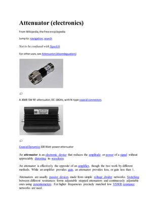
A 30dB 5W RF-attenuator,DC-18GHz,withN-type coaxial connectors
Coaxial Dynamics100 Watt powerattenuator
An attenuator is an electronic device that reduces the amplitude or power of a signal without
appreciably distorting its waveform.
An attenuator is effectively the opposite of an amplifier, though the two work by different
methods. While an amplifier provides gain, an attenuator provides loss, or gain less than 1.
Attenuators are usually passive devices made from simple voltage divider networks. Switching
between different resistances forms adjustable stepped attenuators and continuously adjustable
ones using potentiometers. For higher frequencies precisely matched low VSWR resistance
networks are used.
2. Fixed attenuators in circuits are used to lower voltage, dissipate power, and to improve
impedance matching. In measuring signals, attenuator pads or adaptors are used to lower the
amplitude of the signal a known amount to enable measurements, or to protect the measuring
device from signal levels that might damage it. Attenuators are also used to 'match' impedances
by lowering apparent SWR.
Contents
[hide]
1 Attenuatorcircuits
2 Attenuatorcharacteristics
3 RF attenuators
4 Audioattenuators
5 Componentvaluesforresistive padsandattenuators
o 5.1 Reference figuresforattenuatorcomponentcalculation
o 5.2 Termsused
o 5.3 Symbolsused
o 5.4 SymmetricTpad resistorcalculation
o 5.5 Symmetricpi padresistorcalculation
o 5.6 L-Padfor impedance matchingresistorcalculation
o 5.7 ConvertingT-padtopi-pad
o 5.8 Convertingpi-padtoT-pad
o 5.9 Conversionbetweentwo-portsandpads
5.9.1 T-padto impedance parameters
5.9.2 Impedance parameterstoT-pad
5.9.3 Impedance parameterstopi-pad
5.9.4 Pi-padtoadmittance parameters
5.9.5 Admittance parameterstopi-pad
o 5.10 General case,determiningimpedance parametersfromrequirements
6 Notes
7 References
8 External links
[edit] Attenuator circuits
π-type unbalancedattenuatorcircuit
3. π-type balancedattenuatorcircuit
T-type unbalancedattenuatorcircuit
T-type balancedattenuatorcircuit
Basic circuits used in attenuators are pi pads (π-type) and T pads. These may be required to be
balanced or unbalanced networks depending on whether the line geometry with which they are to
be used is balanced or unbalanced. For instance, attenuators used with coaxial lines would be the
unbalanced form while attenuators for use with twisted pair are required to be the balanced form.
Four fundamental attenuator circuit diagrams are given in the figures on the left. Since an
attenuator circuit consists solely of passive resistor elements, it is linear and reciprocal. If the
circuit is also made symmetrical (this is usually the case since it is usually required that the input
and output impedances Z1 and Z2 are equal) then the input and output ports are not distinguished,
4. but by convention the left and right sides of the circuits are referred to as input and output,
respectively.
[edit] Attenuator characteristics
A RF Microwave Attenuator.Picture courtesyof Herley
Key specifications for attenuators are:[1]
Attenuationexpressedin decibels of relative power.A 3dB padreducespowerto one half,6dB
to one fourth,10dB to one tenth,20dB to one hundredth,30dB toone thousandthandsoon.
For voltage youdouble the dBssofor example 6dBishalf involtage.
Frequencybandwidth,for example DC-18GHz
Power dissipationdependsonmassandsurface areaof resistance material aswell aspossible
additional coolingfins.
SWR isthe standingwave ratiofor inputandoutputports
Accuracy
Repeatability
[edit] RF attenuators
Radio frequency attenuators are typically coaxial in structure with precision connectors as ports
and coaxial, microstrip or thin-film internal structure. Above SHF special waveguide structure is
required.
Important characteristics are:
accuracy,
lowSWR,
flatfrequency-responseand
repeatability.
5. The size and shape of the attenuator depends on its ability to dissipate power. RF attenuators are
used as loads for and as known attenuations and protective dissipations of power in measuring
RF signals.[2]
[edit] Audio attenuators
A line-level attenuator in the preamp or a power attenuator after the power amplifier uses
electrical resistance to reduce the amplitude of the signal that reaches the speaker, reducing the
volume of the output. A line-level attenuator has lower power handling, such as a 1/2-watt
potentiometer or voltage divider and controls preamp level signals, whereas a power attenuator
has higher power handling capability, such as 10 watts or more, and is used between the power
amplifier and the speaker.
Powerattenuator(guitar)
Guitar amplifier
[edit] Component values for resistive pads and attenuators
This section concerns pi-pads, T-pads and L-pads made entirely from resistors and terminated on
each port with a purely real resistance.
All impedances,currents,voltagesandtwo-portparameterswillbe assumedtobe purelyreal.
For practical applications,thisassumptionisoftencloseenough.
The pad is designedforaparticularloadimpedance,ZLoad,anda particularsource impedance,Zs.
The impedance seenlookingintothe inputportwill be ZS if the outputport is
terminatedbyZLoad.
The impedance seenlookingintothe outputportwill be ZLoad if the inputport is
terminatedbyZS.
[edit] Referencefiguresforattenuatorcomponentcalculation
6. Thiscircuitis usedforthe general case,all T-pads,all pi-padsandL-padswhenthe source impedance is
greaterthan or equal tothe loadimpedance.
The L-pad computationassumesthatport1 has the highestimpedance.If the highestimpedance
happenstobe the outputport,thenuse thisfigure.
Unique resistordesignationsforTee,Pi andL pads.
The attenuator two-port is generally bidirectional. However in this section it will be treated as
though it were one way. In general, either of the two figures above applies, but the figure on the
left (which depicts the source on the left) will be tacitly assumed most of the time. In the case of
the L-pad, the right figure will be used if the load impedance is greater than the source
impedance.
Each resistor in each type of pad discussed is given a unique designation to decrease confusion.
The L-pad component value calculation assumes that the design impedance for port 1 (on the
left) is equal or higher than the design impedance for port 2.
[edit] Termsused
Pad will includepi-pad,T-pad,L-pad,attenuator,andtwo-port.
Two-portwill includepi-pad,T-pad,L-pad,attenuator,andtwo-port.
Inputport will meanthe inputportof the two-port.
7. Outputport will meanthe outputportof the two-port.
Symmetricmeansacase where the source andloadhave equal impedance.
Loss meansthe ratioof powerenteringthe inputportof the paddividedbythe powerabsorbed
by the load.
InsertionLossmeansthe ratioof powerthat wouldbe deliveredtothe loadif the loadwere
directlyconnectedtothe source dividedbythe powerabsorbedbythe loadwhenconnected
throughthe pad.
[edit] Symbolsused
Passive, resistive pads and attenuators are bidirectional two-ports, but in this section they will be
treated as unidirectional.
ZS = the outputimpedance of the source.
ZLoad = the inputimpedance of the load.
Zin = the impedance seenlookingintothe inputportwhenZLoad is connectedtothe outputport.
Zin is a functionof the loadimpedance.
Zout = the impedance seenlookingintothe outputportwhenZs isconnectedto the inputport.
Zout is a functionof the source impedance.
Vs = source opencircuitor unloadedvoltage.
Vin = voltage appliedtothe inputportbythe source.
Vout = voltage appliedtothe loadbythe outputport.
Iin = currententeringthe inputportfromthe source.
Iout = currententeringthe loadfromthe outputport.
Pin = Vin Iin = powerenteringthe inputportfromthe source.
Pout = Vout Iout = powerabsorbedbythe loadfromthe outputport.
Pdirect = the powerthatwouldbe absorbedbythe loadif the loadwere connecteddirectlytothe
source.
Lpad = 10 log10 (Pin / Pout ) always.Andif Zs = ZLoad thenLpad = 20 log10 (Vin /Vout ) also.Note,as
defined,Loss≥0 dB
Linsertion = 10 log10 (Pdirect / Pout ).And if Zs = ZLoad thenLinsertion = Lpad.
Loss ≡ Lpad. Loss isdefinedtobe Lpad.
[edit] SymmetricT pad resistorcalculation
see
Valkenburgp11-3[3]
[edit] Symmetricpi pad resistorcalculation
see
Valkenburgp11-3[3]
8. [edit] L-Padfor impedancematchingresistorcalculation
If a source and load are both resistive (i.e. Z1 and Z2 have zero or very small imaginary part) then
a resistive L-pad can be used to match them to each other. As shown, either side of the L-pad can
be the source or load, but the Z1 side must be the side with the higher impedance.
see Valkenburgp11-3[4]
Large positive numbers means loss is large. The loss is a monotonic function of the impedance
ratio. Higher ratios require higher loss.
[edit] ConvertingT-padto pi-pad
This is the Y-Δ transform
[5]
[edit] Convertingpi-padto T-pad
This is the Δ-Y transform
[5]
[edit] Conversionbetweentwo-portsandpads
[edit] T-pad to impedanceparameters
The impedance parameters forapassive two-portare
It isalwayspossible torepresentaresistive t-padasatwo-port.The representationis
particularlysimpleusingimpedance parametersasfollows:
[edit] Impedanceparameters toT-pad
The precedingequationsare triviallyinvertible,butif the lossisnotenough, some of the t-pad
componentswill have negativeresistances.
9. [edit] Impedanceparameters to pi-pad
These precedingT-padparameterscanbe algebraicallyconvertedtopi-padparameters.
[edit] Pi-pad toadmittanceparameters
The admittance parameters fora passive twoportare
It isalwayspossible torepresentaresistive pi padasa two-port.The representationis
particularlysimpleusingadmittanceparametersasfollows:
[edit] Admittanceparameters topi-pad
The precedingequationsare triviallyinvertible,butif the lossisnotenough,some of the pi-pad
componentswill have negativeresistances.
[edit] General case,determiningimpedanceparametersfromrequirements
Because the pad is entirely made from resistors, it must have a certain minimum loss to match
source and load if they are not equal.
The minimum loss is given by
[3]
Although a passive matching two-port can have less loss, if it does it will not be convertible to a
resistive attenuator pad.
10. Once these parameters have been determined, they can be implemented as a T or pi pad as
discussed above.
[edit] Notes
1. ^ Attenuator Overview - a brief review of key specifications
![Fixed attenuators in circuits are used to lower voltage, dissipate power, and to improve
impedance matching. In measuring signals, attenuator pads or adaptors are used to lower the
amplitude of the signal a known amount to enable measurements, or to protect the measuring
device from signal levels that might damage it. Attenuators are also used to 'match' impedances
by lowering apparent SWR.
Contents
[hide]
1 Attenuatorcircuits
2 Attenuatorcharacteristics
3 RF attenuators
4 Audioattenuators
5 Componentvaluesforresistive padsandattenuators
o 5.1 Reference figuresforattenuatorcomponentcalculation
o 5.2 Termsused
o 5.3 Symbolsused
o 5.4 SymmetricTpad resistorcalculation
o 5.5 Symmetricpi padresistorcalculation
o 5.6 L-Padfor impedance matchingresistorcalculation
o 5.7 ConvertingT-padtopi-pad
o 5.8 Convertingpi-padtoT-pad
o 5.9 Conversionbetweentwo-portsandpads
5.9.1 T-padto impedance parameters
5.9.2 Impedance parameterstoT-pad
5.9.3 Impedance parameterstopi-pad
5.9.4 Pi-padtoadmittance parameters
5.9.5 Admittance parameterstopi-pad
o 5.10 General case,determiningimpedance parametersfromrequirements
6 Notes
7 References
8 External links
[edit] Attenuator circuits
π-type unbalancedattenuatorcircuit](data:image/gif;base64,R0lGODlhAQABAIAAAAAAAP///yH5BAEAAAAALAAAAAABAAEAAAIBRAA7)