
Empfohlen
Weitere ähnliche Inhalte
Was ist angesagt?
Was ist angesagt? (20)
Andere mochten auch
Andere mochten auch (20)
Ähnlich wie Activated sludge process design
Ähnlich wie Activated sludge process design (20)
Kürzlich hochgeladen
Kürzlich hochgeladen (20)
Activated sludge process design
- 1. 75th STREET WASTEWATER TREATMENT PLANT UPGRADE PROJECT Basis of Design Memorandum Design Memo No.: DM-3 (REVISED) Date: February 11, 2005 Project/Phase/Task: 124487.001.420 Subject: Activated Sludge Improvements (Includes Aeration Basins, Diffused Air System, and Blower Building) Prepared by: Sean O’Connell, P.E., Brown and Caldwell Chris Douville, P.E., Brown and Caldwell Reviewed by: Boyd Hanzon, P.E., Brown and Caldwell Jenny Hartfelder, P.E., Brown and Caldwell Denny Parker, Ph.D., P.E., Brown and Caldwell John Bratby, Ph.D., P.E., Brown and Caldwell SCOPE OF DESIGN This design memorandum (DM) covers the basis of design to build a two-phase project to replace the existing trickling filter/solids contact (TF/SC) process with a conventional activated sludge secondary process to achieve nutrient removal. This new activated sludge process will provide nitrification and denitrification for nitrogen removal in the first phase, and phosphorous removal in the second phase. Nitrogen and phosphorous removal in this secondary process configuration is termed biological nutrient removal (BNR). The new activated sludge process would include, in part, the following elements of construction: Aeration basins (A-basins): Three in Phase 1, one in Phase 2. Each is approx. 81 ft W x 180 ft L x 19 ft D. Influent (distribution) channel: Phase 1 primarily, but last portion in Phase 2. Effluent (collection) channel: Phase 1 primarily, but last portion in Phase 2. New blower building (with 3 new blowers): Phase 1. Diffused air system: Phases 1 and 2 in aerated zones. DM-3. Activated Sludge Page 1 of 2 P:DataGENBoulder24487 WWTP04 Reports & Deliverables4200 MemorandaDesignMemorandaDesign Memos to Boulder Jan08DM3-A- Basins Feb-05.doc
- 2. Anaerobic and anoxic zone mixers: Phases 1 and 2. Influent channel mixers: Phases 1 and 2. New mixed liquor wasting station, Classifying Selector (2 pumps): Phase 1. Internal mixed liquor recycle (IMLR) pumping: Phase 1 (required for denitrification). Biological phosphorus recycle (Bio-P) pumps: Phase 2. This construction can only be accommodated by demolishing the two largest existing trickling filters (TF). Initially, TF3 will be removed to accommodate the construction of the first two A-basins. The third A-basin (part of Phase 1) and fourth A-basin (to be constructed during Phase 2) will require demolition of TF4. The existing solids contact tank (SCT) will remain in service to provide treatment as part of the revised configuration. TF1 and TF2 will remain, but the media will be removed so that the tanks will be available to use as temporary holding tanks. Table 1 lists some of the assumed effluent limit criteria that were used in the process modeling effort. Please refer to DM-1, Design Flows and Loads, for a more comprehensive presentation of information regarding influent wastewater quality and characterization and process design parameters and assumptions. Table 1. Assumed Effluent Limit Criteria Criteria Value Effluent Ammonia (as N) (Phase 1 and 2) <1.0 mg/L Effluent Total Inorganic Nitrogen (TIN) (Phase 2) <10.8 mg/L Effluent Total P (Phase 2) <1.0 mg/L Please note that more detailed information can be found in the Design Flows and Loads Design Memorandum, DM-1. DESCRIPTION OF IMPROVEMENTS Conventional activated sludge with full BNR will be incorporated at the 75th Street Wastewater Treatment Plant (WWTP) in two phases. BNR will include both nitrogen and phosphorous removal capacity. Phase 1 will provide nitrogen removal capacity via nitrification and denitrification; while Phase 2 will incorporate features to achieve biological phosphorous removal. Even though specific dates for when nutrient criteria will go into effect are not yet established, the City of Boulder has made the decision to incorporate full nitrogen removal capability within the Phase 1 design, which represents a proactive approach to nutrient removal prior to any regulatory mandates. DM-3. Activated Sludge Page 2 of 2
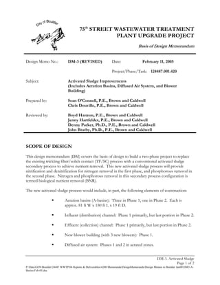
- 3. The main elements of the activated sludge process are summarized in Table 2. The items listed in the Phase 2 column are only those to be installed in that phase, not the total number of units included in Phase 1 and Phase 2. Table 2. System Components Summary Item Capacity/Size (each) Phase 1 Qty. Phase 2 Qty. Activated Sludge Configuration - Nitrogen Phosphorus Removal Removal A-Basins 180 ft L x 81 ft W x 3 1 19 ft D Anaerobic/Anoxic Zone Mixers 5 hp 9 15 Influent Channel Mixers 3 hp 3 1 IMLR Pumps1,2,3 5.5 mgd @ 5 ft TDH 9 3 8.5 mgd @ 5 ft TDH Bio-P Recycle Pumps3 5.5 mgd @ 3 ft TDH - 4 8.5 mgd @ 3 ft TDH Blowers4 9,300 cfm @ 800 hp 3 - Blower Building 4,400 sq. ft. 1 - Fine Bubble Diffused Air System Membranes and ceramic TBD5,6 TBD5,6 disks Classifying Selector7 Pumps 600 gpm @ ~45 ft TDH 2 - 1 IMLR pump size based on total recycle flow of 300 percent of influent maximum month flow. 2 Internal mixed liquor recycle is required for full denitrification (Phase 1). 3 IMLR and Bio-P pumps for future AB4 are sized at 8.5 mgd to accommodate the larger basin volume. 4 Blowers provide firm capacity for maximum airflow with one unit out of service. 5 TBD = to be determined. 6 Membrane quantities could vary greatly depending on what type and manufacturer that might be selected. 7 Classifying selector is a system located in the effluent channel of the A-basins that is designed to be capable of wasting scum as well as the full required volume of waste activated sludge (WAS), or mixed liquor, from the surface of the channel. This system is designed to continuously remove filamentous organisms and scum from the system. Aeration Basin Physical Configurations Primary effluent (PE) will enter the parallel A-basins through a common influent channel. The influent channel will be mixed with surface floating mixers to keep solids in suspension. Slide gates with electric operators will isolate each basin from the influent channel so that each basin can be taken out of service while the other basins remain in service. Floating vertical mixers will be provided along the influent channel to keep solids in suspension, but not introduce oxygen into the wastewater. Each aeration basin will have three passes resulting in a serpentine flow path. A solid concrete baffle wall with notch weirs at the water surface will separate each of six distinct and equal sized zones in the first pass and the beginning of the second pass, Zones 1 through 6 in Figure 1. The DM-3. Activated Sludge Page 3 of 2
- 4. first three of these zones are always unaerated and can serve either as anaerobic or anoxic zones depending on whether nitrate is present in the recycle flows or not. The Zones 4 through 6 can be either aerated or unaerated depending on what process configuration is desired. These three zones are referred to collectively as the “swing zone.” The baffle walls can serve two distinct functions. One function is to provide a somewhat serpentine flow pattern to minimize short-circuiting, as the notch weirs are located on alternating sides of the pass, while the other function is to physically separate the zones that are unaerated from those that are aerated. The two locations that will separate the aerated zones from unaerated will have sufficient freeboard (hydraulic break) to force any possible foam and scum to be washed through the process rather than being allowed to accumulate. Accumulation of foam could promote growth of nuisance organisms (filamentous bacteria). Operations and maintenance procedures should be undertaken to spray the foam out if it builds up significantly. There will be several relatively small openings at the very bottom of these baffle walls to provide a means to drain the tank without having a differential head across the wall during the draining. Anaerobic, anoxic, and “swing” zones all will have surface mixers to keep solids in suspension with minimal air entrainment. Figure 1: Aeration Basin Zone Definition Schematic 1 2 3 4 5 7 6 8 Each A-basin will be a three-pass plug flow reactor equipped with fine bubble diffused aeration in the “swing” and aerated zones. The density of the diffusers will be greatest at the head end of the aerated portion of the tank and the density will decrease toward the end of the basins. The aeration system will be controlled with a series of airflow meters, dissolved oxygen monitors, and airflow control valves. The airflow rates and aeration pressures also will tie into the main blower control logic to operate in the preferred mode, a “Most Open Valve” (MOV) control scheme. This MOV logic relates header pressure to the airflow set point by defining a mathematical function which relates air header pressure to the most open airflow control valve position of an aeration cell. In an MOV controlled system, the airflow control valves find a natural equilibrium, usually with a minimal pressure drop (often less than 0.1 psig), which promotes optimal energy efficiency in the system and provides a self-correcting system in the event of an unusual occurrence. Such an occurrence might be when an aeration zone pipe header gets partially filled with water. The MOV control would sense the increased pressure, then open that zone valve to get maximum airflow through to flush out the water, at which time it will then close back down to its equilibrium point as the pressure drops back to normal. This happens automatically without operator intervention. DM-3. Activated Sludge Page 4 of 2
- 5. Mixed liquor will flow out of each A-basin over a full-width broad-crested weir. This provides a reliable means of hydraulic control through the basin while at the same time positively forcing scum and foam to exit the basins. The mixed liquor leaving the new A-basins is collected in the effluent channel and transported to the existing SCT influent channel and SCT, which will remain untouched as part of this design. The effluent channel from the new aeration basins will incorporate a surface wasting station, or classifying selector. The classifying selector will allow for the necessary wasting of solids as required by the process, achieved by pumping mixed liquor as opposed to traditional RAS wasting. This promotes elimination of foam and scum to reduce propagation of filamentous and other problematic organisms. This also provides the most reliable and robust means of SRT (solids retention time, known by different terms including “sludge age”) control of the biomass inventory in the A-basin reactor tanks. The effluent channel will be mixed using fine bubble diffused air, supplied from the main aeration header. This fine bubble diffused air also will promote flotation and separation of nuisance organisms for removal by the surface baffle of the classifying selector. Several side-stream return flows will be introduced in the aeration basins to provide treatment and the necessary Phase 1 (nitrogen removal) and Phase 2 (phosphorous removal) features required to achieve the respective treatment goals. Phase 1 Configuration For Phase 1, nitrification will be achieved in the aerated portion of the A-basin reactors. Partial denitrification will be achieved simply by incorporating RAS with the PE at the front of the unaerated zone in each basin (at Zone 1 in Figure 2). RAS will be distributed in a dedicated splitter structure where cutthroat flumes will hydraulically split the flows equally among the new aeration basins that are in service. This structure will serve as the mechanism to distribute RAS flow among the aeration basins for both Phases 1 and 2. In Phase 2, however, the discharge location of the RAS piping will be reconfigured to discharge into Zone 3 in each aeration basin (see Figure 3). Near-complete denitrification can be expected in the Phase 1 design due to the incorporation of internal mixed liquor recycle (IMLR) flow. In order to incorporate denitrification, recycle of up to three times the max month flow (300%) of fully nitrified mixed liquor will be required. This nitrified mixed liquor will be returned to the very beginning of the anoxic zone in each A-basin (Zone 1 in Figure 2). The way the process model has currently been set up, and the way that the process operation is planned, this nitrified mixed liquor will need to come from the very tail end of the aerated portion of the system. To promote mixing of the various return flows, a chimney baffle structure will be utilized. The structure will have a cross-section of 6 ft by 10 ft. Flow enters at the top of the structure, and must travel downwards toward the bottom of the basin to exit. Both RAS and IMLR flows will be pumped into the chimney baffle to mix with the influent wastewater. A chimney baffle will be located in Zone 1 and Zone 3 of each basin. During Phase 1 the Zone 1 chimney baffle will accept RAS and IMLR, while in Phase 2 the Zone 3 chimney baffles will be utilized. Each chimney baffle DM-3. Activated Sludge Page 5 of 2
- 6. will include a manual slide gate located at the water surface to allow the occasional release of any trapped floatables, if present. Please note that the “anoxic” zone shown in Figure 2 is defined as such since there is no free dissolved oxygen present in this zone. However, there will be nitrate oxygen present due to its presence in the RAS and IMLR flows. Figure 2: Phase 1 Nitrogen Removal Configuration ANOXIC 670 diffusers AB3 1170 diffusers NOTE: Red lines are IMLR flow IMLR 700 diffusers ANOXIC 670 diffusers Primary Effluent AB2 1170 diffusers IMLR 700 diffusers ANOXIC 670 diffusers Existing SCT AB1 1170 diffusers IMLR RAS 700 diffusers Phase 2 Configuration The Phase 2 configuration has been designed to achieve biological phosphorus removal and accommodate ultimate reactor volume requirements by adding a fourth basin. See Figure 3 for the Phase 2 A-basin process configuration. During Phase 2, the internal mixed liquor recycle (IMLR) flow will be rerouted to enter Zone 3 instead of Zone 1. In addition to the IMLR flow, RAS will also be brought into the beginning of the anoxic zone, Zone 3, under the Phase 2 configuration. RAS recycle rates will be flow paced with variable rate pumping up to 100% of the maximum month design flow, or 25 mgd. In order to achieve bio-P removal, there is the need for one additional internal recycle. This recycle requires that anoxic zone effluent (at end of Zone 6 in Figure 3) will be pumped back to the beginning of Zone 1. This recycle rate is a constant rate at 100% of the maximum month flow, or 25 mgd. Installing low head axial flow pumping and a piping can easily incorporate this bio-P recycle into the Phase 2 A-basin configuration. The design intent is to install a single bio-P pump per basin. DM-3. Activated Sludge Page 6 of 2
- 7. Provisions will be made during the Phase 1 design to incorporate necessary Phase 2 features to reconfigure the RAS and IMLR discharge locations and to make it easy to install the necessary bio-P recycle pumping components. These features will largely include strategic placement of pipe wall thimbles with associated caps and/or blind flanges where future piping can easily be bolted up. Oxygen demand will actually decrease slightly from Phase 1 (nitrogen removal) to Phase 2 (phosphorus removal). Initially, the basins will be designed with provisions that allow the tanks and aeration system to accommodate the Phase 2 features including the anaerobic, anoxic, and “swing” zones and a diffused air system that will provide the Phase 1 oxygen requirements. This will provide the greatest flexibility for conversion to the Phase 2 configuration by allowing for the “swing” zone to be aerated, or not, and will provide more than adequate diffusers which can actually be removed and easily capped to meet the lower oxygen demand requirements of Phase 2. Aeration Basin Effluent Channel The aeration basin effluent will be collected in a common channel that runs along the western fence line of the WWTP site. Due to the tight constraints for construction of this channel, several considerations need to be addressed with respect to the existing Trickling Filter structures and the existing Gunbarrel/IBM interceptor sewer that runs along that west plant boundary in the same vicinity as the proposed effluent channel. The aeration basin effluent channel has been designed with the same north-south alignment as the existing SCT influent channel, which will allow for the existing Gunbarrel/IBM interceptor to remain in its present location, undisturbed by the effluent channel construction. The details related to the tie-in of the new aeration basin effluent channel to the existing SCT influent channel at the interstage pump station (IPS) have not been fully resolved. The IPS will not be needed once the Phase 1 aeration basin system is operational, however, the IPS will be required during the early stages of construction when TF4 is still on-line. No specific solution has been developed at the time of this memorandum on how to handle this issue. Brown and Caldwell will examine in more detail the available information about the IPS construction. The required construction sequencing will be discussed by Brown and Caldwell’s construction management staff to identify the best solution to accomplish the tie-in.. A future meeting with the City of Boulder will be conducted to discuss the alternatives. DM-3. Activated Sludge Page 7 of 2
- 8. Figure 3: Phase 2 Nitrification, Denitrification, and Biological Phosphorous Removal Configuration ANAEROBIC ANOXIC Bio-P 1500 diffusers AB4 ANOXIC IMLR 700 diffusers ANAEROBIC ANOXIC Bio-P 1500 diffusers AB3 ANOXIC NOTE: Red lines are IMLR flow and IMLR the Green lines are 700 diffusers Bio-P recycle ANAEROBIC ANOXIC Primary Bio-P Effluent 1500 diffusers AB2 ANOXIC IMLR 700 diffusers ANAEROBIC Existing ANOXIC SCT Bio-P 1500 diffusers AB1 ANOXIC IMLR RAS 700 diffusers Full Scale Process Proof Testing The City of Boulder should consider the opportunity to proof test the full-scale facility once the Phase 1 improvements have been commissioned and consideration is being given to the design of the Phase 2 improvements. By incorporating the Phase 2 configuration into only one of the new Phase 1 aeration basins, the full-scale facility can be tested to establish the true nitrification, denitrification, and bio-P basis of design parameters. An example of proof testing might be to establish how extensive the bio-P might be without the addition of methanol or, further, to establish a more exact methanol quantity that might be necessary to achieve the desired effluent phosphorous concentration. DM-3. Activated Sludge Page 8 of 2
- 9. PROCESS DESIGN CRITERIA Basic design assumptions are listed in Table 3 (see DM-1): Table 3. Design Criteria Criteria Value Flows and Loads: Annual Average Flow 20.8 mgd Maximum Month Flow1 25 mgd Maximum Daily Flow 40.5 mgd Peak Hour Flow 53.5 mgd Maximum Month BOD Load1 36,000 lb/d Minimum Temperature 11.8 oC Influent Concentrations: Maximum Month Average COD 347 mg/L Maximum Month Average TKN 24.1 mg-N/L Maximum Month Average Total P 4.7 mg-P/L 1 Assumed from Wastewater Utility Plan. Based on the design influent characteristics, reactor volumes and air requirements for the activated sludge system were determined using the BioWin simulation model. Special wastewater sampling was carried out for a two-week period in April 2004. The information developed from this focused sampling event produced composite and diurnal site-specific wastewater characterization and provided appropriate model input data for dynamic (diurnal) and steady state analyses with BioWin. The dynamic model simulation allows for better estimation of the required range of oxygen demand in the process which leads to a more appropriate sizing criteria (and turndown) of the required aeration air blowers. Principal design requirements, as they affect the sizing of process units, are assumed to be as listed in Table 4: DM-3. Activated Sludge Page 9 of 2
- 10. Table 4. Preliminary Effluent Quality Design Assumptions Criteria Value (mg/L) Phase 1 – Nitrification Only Effluent Ammonia Concentration <1.0 Phase 2 – Nitrification, Denitrification, and Phosphorous Removal Effluent Ammonia Concentration <1.0 Effluent TIN Concentration <10.8 Effluent Total P Concentration <1.0 Reactor volumes were determined to be as listed in Table 5, below. Please note that the volumes are based on nominal dimensions where each 81 foot wide basin is split into three equal width passes (assumed at 27-feet wide), the basin length is 180 feet, each of Zones 1-6 (refer to Figure 1, above) are equal length (or 36-feet), and an assumed water depth of 19 feet. Please also note that these volumes may vary slightly, on the high side, from the process modeling assumptions due to making the nominal structural dimensions simple rounded numbers. Table 5. Reactor Volumes Summary Criteria Value (MG)1 Phase 1: Existing Volume of SCTs 1.2 Total Volume of New Construction (A-basins 1, 2, & 3) 6.1 Total Volume2 7.3 Total Volume of New Anoxic Selectors 1.22 Total Volume of New Aeration Reactors 4.88 Phase 2: Existing Volume of SCTs 1.2 Total Aeration Basin Volume (A-basins 1, 2, 3, & 4) 9.14 Total Volume2 10.34 Total Volume of New Anaerobic Selectors 1.22 Total Volume of New Anoxic Reactors 2.43 Total Volume of New Aeration Reactors 5.49 1 MG stands for million gallons. 2 This includes the existing volume of the SCTs, which will be situated downstream of the new reactor construction. The primary mode for wasting sludge will actually be through wasting mixed liquor from the surface wasting station, or classifying selector. This provides the most robust, yet simple, means of SRT (sludge age) control by simply allowing the operators to adjust the SRT through the plant programmable logic controller (PLC). If an 8-day SRT is desired, this value is entered at the PLC. DM-3. Activated Sludge Page 10 of 2
- 11. The pump speed is adjusted to a rate needed to pump a daily volume equal to 1/8 of the aeration basin volume. If a 14-day SRT is required, then the pumps would waste a volume equal to 1/14 of the aeration basin volume. The SRTs needed to meet the required plant effluent limits are anticipated to range from 8 to 14 days. This equates to a waste flow rate of mixed liquor of 350 (minimum Phase 1 rate) to 900 gallons per minute (gpm) (maximum Phase 2 rate). Mixed liquor concentration, on average, should be about 3,000 mg/l. The required internal mixed liquor recycle in Phase 2 was determined to be as much as three times the maximum month flow, or 75 mgd. Maximum month oxygen demands were estimated to be as follows. These oxygen demands are the total oxygen demands for the entire aeration system, including the existing SCTs. Average: 33,700 lb/d Maximum: 70,900 lb/d Minimum: 20,130 lb/d Maximum month air requirements were estimated as shown in Table 6. Table 6. Maximum Month Air Requirements (Total Aeration Basin Volume) Phase 1 Phase 2 Average, SCFM 9,600 9,200 Maximum, SCFM 18,400 20,700 Minimum, SCFM 5,970 5,130 Maximum month air requirements for the new A-basins (excluding the existing solids contact aeration tanks) are summarized in Table 7. Table 7. Maximum Month Air Requirements (New Aeration Basin Volume Only) Phase 1 Phase 2 Average, SCFM 8,860 8,470 Maximum, SCFM 16,300 18,750 Minimum, SCFM 5,500 4,660 In order to achieve the total nitrogen limit that was used as a basis of design for Phase 2, methanol will need to be used to provide a carbon source to drive the complete denitrification of the mixed liquor. Methanol addition, in the amount of approximately 2,500 gallons per day would be added to each of the basins at the head end of the anoxic zone. Although not the primary driver, the biological phosphorous (bio-P) removal is also enhanced and improved with the methanol addition. Methanol storage and feed facilities are not part of the scope of this Phase 1 design. Although planned for the Phase 2 configuration, once the Phase 1 system is online, it will provide an opportunity for the City of Boulder to do a full-scale proof test for denitrification and bio-P removal, as discussed previously. This would allow the City of Boulder to establish exactly what will DM-3. Activated Sludge Page 11 of 2
- 12. be required as far as recycle flows, methanol addition, and various other process variables to achieve the Phase 2 goals prior to Phase 2 being constructed. CDPHE DESIGN CRITERIA In accordance with the Colorado Department of Public Health and Environment (CDPHE) Design Criteria Considered in the Review of Wastewater Treatment Facilities, Policy 96-1 (May 14, 2002), the following criteria apply to the design of the proposed activated sludge system. In particular, Article 5.14 of this policy covers activated sludge system criteria. Table 8 provides a bulleted list of those categories in Article 5.14 and the corresponding project-specific criterion. DM-3. Activated Sludge Page 12 of 2
- 13. Table 8. CDPHE Criteria Summary CDPHE Policy CDPHE Requirement Brown and Caldwell Design 96-1 Citation Classification: - Activated sludge with BNR (nitrogen Article 5.14.1 and phosphorus) Unusual Considerations for abnormal BOD5 No unusual conditions are anticipated. Installation: concentrations, unusual aeration WWTP serves City of Boulder and is Article 5.14.2 periods, significant amounts of typical domestic wastewater. industrial wastes, etc. Loading Seasonal or short-term loads and The final process sizing will take into Considerations: flows account both steady state and dynamic Article 5.14.3 conditions. A-Basins 15.14.4 Multiple Units: At >0.25 mgd, multiple units are to be Four new A-basins will be constructed Article 5.14.4.a provided. (three Phase 1, one Phase 2) and the fourth secondary clarifier will be constructed. Freeboard: >18-in. (0.5 M) at peak flow >18-in. (0.5 M) at peak flow Article 5.14.4.b Basin Geometry: Basin geometry is to be considered to Fine bubble diffused aeration, surface Article 5.14.4.c optimize oxygen transfer, mixing, mixers, and hydraulic controls have hydraulics, etc. been implemented to provide appropriate optimal performance. Flexibility: Facilities for flexible operation Flexibility will be provided as much as Article 5.14.4.d is practical considering the configuration required for the BNR process. Design Parameters: Article 5.14.4.e – See Table 9, Comparison of Policy 96-1 Criteria to Design Parameters DM-3. Activated Sludge Page 13 of 2
- 14. CDPHE Policy CDPHE Requirement Brown and Caldwell Design 96-1 Citation Air Supply (General): Article 5.14.5 DO The ability to maintain at least 2 mg/L ≥ 2 mg/L DO, not including the Concentration: of DO under all conditions of loading. anaerobic and anoxic zones required Article 5.14.5.a for nitrogen and phosphorous removal. Min. Air Supply No state requirements for this under a Final air requirements have not been Rates: Article conventional activated sludge BNR determined at the time of this DM. 5.14.5.b configuration. Sufficient air will be provided to support all treatment objectives. Mixing: Article Enough energy via air or mechanical Mechanical mixing for unaerated zones 5.14.5.c mixing to keep solids suspended. at 0.15 hp/1,000 cu. ft (4W/cu. m). Minimum air mixing at 0.12 cfm/sq. ft Mixing: Article Facilities preferably allow continuous Variations in airflow requirements will 5.14.5.d aeration yet also allow variation in the likely be based on an MOV control amount of aeration. concept which will be programmed into the blower control package. DM-3. Activated Sludge Page 14 of 2
- 15. CDPHE Policy CDPHE Requirement Brown and Caldwell Design 96-1 Citation Diffused Air Systems: Article 5.14.6 Multiple Units: Multiple blowers to meet the Three blowers are planned for; two will Article 5.14.6.a maximum air demand with the single provide required firm capacity. largest unit out of service (firm capacity). Design Air filters, maximum air and/or All these factors will be incorporated Approach: wastewater temperatures, and into the design. Article 5.14.6.b elevation must be considered. Diffuser System Aeration system must be capable of System will be designed to deliver peak Capacity: Article delivering 150 percent of average air. oxygen demand at 210% of average 5.14.6.c (max. month peak O2 to avg. O2) Maintenance In-situ means of cleaning, redundant In-situ means of cleaning, redundant Considerations: tanks, or nonclog diffusers for tanks, tank drains, and nonclog Article 5.14.6.d intermittent aerated zones. diffusers for intermittent aerated zones will be incorporated into the design. Air Control Individual diffuser header assemblies Individual diffuser header assemblies Valves: Article with air control valves should be will be provided with air control valves. 5.14.6.e provided. These valves are basically All valves for throttling applications for open or closed operation but also will be designed for on/off should be of the throttling type. isolation service. Mechanical Aeration Systems: Article 5.14.7 – Not applicable to this design. Other Aeration Systems: Article 5.14.8 – Not applicable to this design. DM-3. Activated Sludge Page 15 of 2
- 16. CDPHE Policy CDPHE Requirement Brown and Caldwell Design 96-1 Citation Process Control Equipment: Article 5.14.9 Return Sludge Provisions for monitoring, sampling, All features will be incorporated into Equipment and and controlling the return sludge flow the design per State requirements.1 Flow to be provided. Sludge shall be Measurement1: returned continuously and flow rates Article 5.14.9.a shall be variable to any rate within the limits of Policy 96-1,Table 5. Waste Sludge Similar requirements to Article Similar facilities will be provided on Equipment and 5.14.9.a, above. waste sludge systems as those provided Flow on the return sludge systems, in Measurement1: accordance with State requirements.1 Article 5.14.9.b Polishing Ponds: Article 5.14.10 – Not applicable to this design. Sludge Holding Facilities: Article 5.14.11 – Not applicable to this design. 1 Return and waste sludge handling systems are covered under DM-4, Secondary Clarifier 4 and Associated Pumping. Table 9 shows a comparison of those criteria required by Policy 96-1, Table 5 for conventional activated sludge versus Brown and Caldwell’s design parameters. Table 9. Comparison of Policy 96-1 Criteria to Design Parameters CDPHE Brown and Parameter Requirement Caldwell Value Avg. Aeration Time (hrs) 4 to 8 7 Avg. Space Loading (lb BOD/1,000 cu. ft) < 40 27 Average Mixed Liquor Suspended Solids (MLSS) 1,500 to 4,000 2,500-3,000 Concentration (mg/L) Average Loading Factor – Food to Microorganism 0.2 to 0.5 0.22 (F/M) (lb BOD/lb Mixed Liquor Volatile Suspended Solids [MLVSS]/day) Design Recycle Range (ratio to forward flow) 0.15 to 1.25 1.0 DM-3. Activated Sludge Page 16 of 2
- 17. PROCESS EQUIPMENT SUMMARY Blowers Per CDPHE criteria, firm capacity must be provided for the aeration system by providing aeration capacity with the largest blower unit out of service at the maximum loading condition. Based on the process design criteria, this results in needing a total air supply requirement of 18,800 scfm split between two blower units with a third equivalent size unit out of service. Table 10 lists blower quantities and sizes. Table 10. Blower Quantity and Sizes Phase 1 Phase 2 No. of Units 3 - Capacity, each, scfm 9,400 - Approx. Discharge Pressure, psig 14.0 - Type Single Stage Centrifugal - Horsepower per unit 800 - An extensive life-cycle cost analysis was done for both single-stage and multi-stage blowers. Due to the variation in static water level (static pressure on blowers) and the diurnal process air demand, it is critical to select a blower that can serve all anticipated air flow and discharge pressure requirements while also providing an energy efficient solution. This life cycle cost analysis resulted in establishing that the single-stage centrifugal blowers has the overall lowest annual operating cost while having a relatively equal 20-year total cost of ownership. Other non-economic factors came into the decision as well, such as unit responsibility, aeration system integration (aeration system instrumentation and controls), client preferences, etc. Brown and Caldwell has experience with the three major manufacturers of these types of blowers for the wastewater aeration applications. As of the time of this updated Design Memorandum, the City of Boulder has agreed to enter into negotiations with Turblex, Inc. to try to come to an agreement on a scope of supply and agreed upon price for a fully integrated package. This negotiated package will then be assigned as part of the construction contract for the Contractor to purchase, take delivery, store, install, startup and commission the package. Mixers The anaerobic and anoxic zones, as well as the A-basin influent channel, will be mechanically mixed to prevent solids deposition in those areas. The design is based around an energy input at 0.15 hp/1,000 cu. ft of mixed tank volume (roughly equivalent to 0.02 hp/1,000 gallons). Based on the volumes of these areas discussed previously, the mixer quantities and sizes are listed in Table 11. DM-3. Activated Sludge Page 17 of 2
- 18. Table 11. Mixer Quantity and Sizes Phase 1 Phase 2 Influent Channel Mixers: No. of Units 3 1 Type Surface direct drive Surface direct drive Horsepower per unit 3 3 Anaerobic/Anoxic Zone Mixers: No. of Units 9 15 Type Surface direct drive Surface direct drive Horsepower per unit 5 5 Please note the number of units corresponds to six units spaced evenly through the anaerobic/anoxic zones of each basin and one mixer per basin for influent channel mixing. Diffusers Brown and Caldwell invited two main manufacturers of fine bubble diffusers (Sanitaire and EDI) to talk with City of Boulder staff about diffuser types and alternatives. City staff also spoke with other installations of ceramic disks since Boulder’s only experience has been with membranes. Out of this, the decision has been made to install disk diffusers in all the new aeration basins. The membrane disks will be installed in the “swing zone” which may or may not be aerated. Ceramic disks will be installed in those aeration zones that will be fully aerated on a continuous basis. The preliminary design criteria for the fine bubble diffused air system have been summarized in Table 12. Please note that some of these parameters have ranges due to the fact that certain portions of the A- basins have different values depending on the air demand, diffuser density, maximum and minimum air flow requirements, etc. Based on these preliminary diffuser design criteria we have established the approximate number of diffusers for each of the aerated zones as summarized in Table 13, below. Please refer to Figure 1 above for the Zone references as stated in Table 13. DM-3. Activated Sludge Page 18 of 2
- 19. Table 12. Diffuser Design Criteria Design Parameter Value Site Elevation, feet MSL 5,135 Water temperature, oC 28 Air temperature, oC 32 A-basin liquid depth, feet 19 Diffuser submergence, max., feet 18 SOTE1 0.42 to 0.52 Air flow per diffuser, scfm/diff. 0.55 to 2.66 Relative diffuser density2 5.67 to 20.4 α3 0.37 to 0.63 (weighted avg. of 0.5) 1 Standardized Oxygen Transfer Efficiency, dimensionless. 2 This is the surface area of tank floor divided by the surface area of the diffusers. 3 α (alpha) is a mass transfer correction factor that is a ratio of mass transfer in wastewater divided by the mass transfer expected in clean tap water. DM-3. Activated Sludge Page 19 of 2
- 20. Table 13. Estimated Diffuser Quantities1 Basin Zones2 Diffuser Quantity (each basin) Phase 1: 1, 2, and 3 None, anoxic conditions 4 plus 5 670 6 plus 7 1,170 8 700 Phase 2: 1 and 2 None, anaerobic conditions 3, 4, 5, and 6 None, anoxic conditions 7 1,500 8 700 1 Diffuser quantities are only estimated here based on membrane disk diffusers and typical design criteria. Depending on the manufacturer and type that is selected, these quantities may vary. However, these numbers can be used to give a relative density comparison from zone to zone. 2 Refer to Figure 1 of this design memorandum for illustration that defines each of the basin zones. IMLR Pumps Process design for the ultimate future condition for denitrification (employed in Phase 1) was based on the assumption that up to three times the design maximum monthly flow of fully nitrified mixed liquor would be recycled to the anoxic zones in the aeration basin reactors. Fully nitrified mixed liquor will be pumped from the effluent end of the aeration basins (last part of Zone 8) into the chimney baffle located in Zone 1 (Zone 3 during Phase 2). The IMLR pumps summarized in Table 14 below are based on this assumption. Table 14. IMLR Pump Quantity and Sizes Phase 1 Phase 2 No. of Units 9 3 Capacity, each, gpm 3,800 (5.5 mgd) 3,800 (5.5 mgd) Total Head, ft 4.2 4.2 Assumed efficiency, percent 60 60 Type Axial flow Axial flow Horsepower per unit, max. 20 20 DM-3. Activated Sludge Page 20 of 2
- 21. Slide Gates Plant staff have expressed that they are systematically replacing many of their existing aluminum and cast iron slide gates due to corrosion. They are replacing them with stainless steel units, which actually are very cost competitive when compared to the other materials available. Table 15 summarizes the slide gates required for the A-basins. Currently the concept would be to have influent channel isolation gates coupled with a full-width broad-crested effluent weir that would not be submerged at peak design flow conditions. In the event that this configuration is not desirable, effluent slide gates can be incorporated for isolating tanks. Table 15. Summary of A-Basin Slide Gate Requirements Phase 1 Phase 2 No. of Units 3 1 Type/Material Self-Contained / Stainless Self-Contained / Stainless Steel Steel Size 72 in. W x 84 in. H 72 in. W x 84 in. H Actuator Type Electric Motor Electric Motor STRUCTURAL AND ARCHITECTURAL The architecture for the new facilities will be designed to closely match the materials of construction and the overall concepts currently at the existing plant. Brick veneer will be used consistent with the existing architectural style. Please refer to the architectural basis of design memorandum DM-10 for more details with respect to the architectural design as related to this facility. HEATING, VENTILATION AND AIR CONDITIONING (HVAC) Aeration basin and blower building HVAC design criteria are not addressed in this memorandum. There are no HVAC requirements for the aeration basins. Please refer to design memorandum DM- 8 for the comprehensive project HVAC design criteria, applicable for the blower building. DM-3. Activated Sludge Page 21 of 2
- 22. NFPA 820 AREA EVALUATION NFPA 820 area classifications are described in DM-13. According to NFPA 820 (Table 5.2, Row 7, 2003 Edition), because the A-basins are open to the atmosphere (not covered or enclosed) and are preceded by primary sedimentation, the process is considered unclassified. Therefore, no explosion proof or intrinsically safe devices are required around the A-basins. NFPA 820 does not address specifically a separate blower building as is planned for the new aeration system. Therefore, industry best practices will be employed to provide ambient temperatures and sufficient ventilation to protect electrical and mechanical equipment. City of Boulder health and safety standards will have to be employed to ensure that operations staff health and safety are provided for in accordance with City requirements. ELECTRICAL Please refer to the electrical basis of design memorandum Electrical Power Distribution, DM-11, which summarizes the comprehensive project electrical design criteria and applicable codes for the aeration basins, aeration system, and blower building electrical design. INSTRUMENTATION Please refer to the instrumentation basis of design memorandum Controls and Instrumentation, DM-12, which summarizes the design criteria for the instrumentation and controls for the aeration basins, aeration system, and blower building design. OTHER CONSIDERATIONS OUTSIDE THE SCOPE OF THIS DESIGN Provisions can be made for contact treatment of peak flows, in excess of the design peak hourly flow of 53.5 mgd, which will minimize solids loading rates to the secondary clarifiers during such events. However, with careful process control and solids inventory management, the process is designed and can be operated up to this design peak hourly flow. The process control constraints are discussed in more detail in DM-4, Secondary Clarifier 4 and Associated Pumping. Review of the existing plant piping and the existing secondary pump station indicates that the existing secondary pump station discharge piping can be modified so that plant flows in excess of this design flow could effectively bypass the new aeration basins and receive contact treatment in what is currently known as the SCTs. This secondary pump station piping reconfiguration would require that the pipe be tied into the discharge side of the existing interstage pumping station (IPS). The IPS will not remain in service once the new activated sludge process comes online. Pumps P3101, P3102, and P3103 should be left in place, in working order, and with all electrical service in tact to serve as the contact treatment pumping station. The design of this revised pumping scheme is not included in the scope of this design. DM-3. Activated Sludge Page 22 of 2