Nicomatic cata2019-1306-EMM rugged miniaturized connector
•
0 gefällt mir•75 views

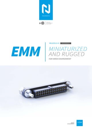
EMM catalog updated. EMM is 1.27 pitch connector for harsh environment applications: Aerospace, UAV, defense, etc.EMM meets and exceed MIL83513 standard performances. defence, mil connectors, mil83513

Empfohlen
Empfohlen
Weitere ähnliche Inhalte
Was ist angesagt?
Was ist angesagt? (19)
Ähnlich wie Nicomatic cata2019-1306-EMM rugged miniaturized connector
Ähnlich wie Nicomatic cata2019-1306-EMM rugged miniaturized connector (20)
Kürzlich hochgeladen
Kürzlich hochgeladen (20)
Nicomatic cata2019-1306-EMM rugged miniaturized connector
- 1. EMM MINIATURIZED AND RUGGED FOR HARSH ENVIRONMENT C R E A T I V E I N T E R C O N N E C T S O L U T I O N S 1.27mm pitch _ HARSH ENVIRONMENT MIL83513-G PERFORMANCES
- 2. MAIN FEATURES 03 OVERALL DIMENSIONS 06 A WORD FROM THE DESIGNER 07 MAIN APPLICATIONS 08 PRODUCT SPECIFICATIONS 10 PRODUCT CONFIGURATION Straight on PCB 16 90° on PCB 17 Cabling 18 Tooling 19 MAKE YOUR DREAMS A REALITY AS AN ENGINEER YOU CAN MAKE HISTORY TOGETHER WE'LL FIND THE BEST SOLUTION 02 I EMM CONNECTORS OUR LEITMOTIV SUMMARY WE ARE NICOMATIC _ Creative interconnect solutions provider
- 3. INTRO Designed to meet the performance requirements of MIL 83513-G, the range combines rugged design with enhanced electrical and environmental performances FROM THE IDEA TO THE FINISHED PRODUCT → DESIGNED IN 2018 EMM ACHIEVES EXTRA SPACE AND WEIGHT REDUCTION TO MEET YOUR MINIATURIZATION NEEDS IN THE MOST EXTREME ENVIRONMENTS FROM THE Easy installation thanks to a perfect balance between the pitch and the overall dimensions of the range. Male contacts, thinner by essence, are protected inside the insulator. Featured exclusively on 90° connectors mount, contacts are protected at the back by an ingenious shape, also guaranteeing a perfect alignment of the contacts. SPACE SAVING Straight male and female thru-hole 90° male and female thru-hole Cable AWG 24-30 04 to 60 pins. HIGH MODULARITY REVERSED CONTACTS 90° BACK PROTECTION 1.27 mm pitch µ Gold mm Secure wiping length MATERIALS Locking and guiding functions available, adaptable on both male and female connectors INTERCHANGEABLE HARDWARE Moulding: High performance glass fiber composite (LCP) Male pins: Copper alloy, Au 0.75µ Female pins with tulip technology (clip with 4 finger spring contact) • Outer: Copper alloy, Au 0.125µ • Inner: Berrylium copper, Au 1.27µ Fixing hardware: passivated stainless steel 300 series
- 4. 03 I APPLICATIONSI DMM CONNECTORS SPACE & WEIGHT SAVING FUTURE IS SMALLER
- 6. 06 I EMM CONNECTORS EMM Overall dimensions MALE AND FEMALE STRAIGHT ON PCB MALE 90° AND FEMALE STRAIGHT ON PCB MALE ON CABLE AND FEMALE 90° ON PCB MALE ON CABLE (CAPTIVE SCREW) AND FEMALE 90° ON PCB MALE ON CABLE AND FEMALE STRAIGHT ON PCB MALE ON CABLE (CAPTIVE SCREW) AND FEMALE STRAIGHT ON PCB MALE AND FEMALE 90° ON PCB MALE STRAIGHT AND FEMALE 90° ON PCB → MARKING AND POLARIZATION MARKING NCM = NicomaticTH brand AASS = year + week batch EXAMPLE AA (Year):2018 SS (Week):09 . Pin nbr 1
- 7. I DMM CONNECTORS A FEW WORDS Jérôme Designer & Project manager “This project is a model of collective success. All Nicomatic departments have been involved and brought their own touch of innovation to the global EMM product offer. Focusing on simplicity and efficiency my main objective was to limit the mechanical stress. As a result the EMM connector meets the global constraints of our customers, from both a functional and a service perspective. What we experienced and learned during the development of the EMM will benefit our other connector ranges too. EMM already offers a great modularity, and it is just the beginning !”
- 8. 08 Main applicationsEMM I EMM CONNECTORS Proven technology / Harsh environment requirements → SUGGESTIONS → SUGGESTIONS → SUGGESTIONS DMM shielded harness Mixed DMM with data and coax contact Mixed DMM with data and coax contact Custom IP67 DMM DMM with Flange DMM RF Grounded DMM RF Grounded Custom gold DMM Custom gold DMM → DEFENCE High vibration Space saving Modularity Note: Our products help to make easier maintenance → SPACE Weight saving High altitude Outgassing Note: There is no wayback for your projects → MOTOR SPORT Reliability Shock resistance High vibration Note: Secure your equipment TMC
- 9. 09I EMM CONNECTORS → UAV → ROBOTICS → CIVIL AVIATION → SUGGESTIONS → SUGGESTIONS → SUGGESTIONS DMM for cabling DMM 3 rows DMM for cabling Weight saving Shock resistance Weight saving Space saving Space saving Modularity Modularity Modularity Metalized composite DMM Mixed DMM with data and power contact Metalized composite DMM Note: Data reliability is a matter of life Note: Saving weight and space Note: High modularity Mixed DMM with data and power contact DMM Multimix DMM with racking fixing NEED A MINIATURIZED & RUGGED CONNECTOR ? EMM IS YOUR SOLUTION Space saving
- 10. 10 I EMM CONNECTORS
- 11. HIGHEST REQUIREMENTS PRODUCT SPECS CHALLENGE YOUR LIMITS ALL OUR ENGINEERS SUPPORT YOU We bring you concrete tips. Consult test reports in free access on our website ! → services / lab reports ACTIONS SPEAK LOUDER THAN WORDS MIL-DTL-83513G PERFORMANCE MEET OR EXCEED 11I EMM CONNECTORS
- 12. 12 I EMM CONNECTORS MIL 83513-G Requirements EMM Results Electrical performance requirements Dielectric withstanding voltage sea level EIA-364-20C (Between all adjacent contacts & fixings) Dielectric withstanding voltage @sea level: 600 V RMS. Connectors shall show no evidence of breakdown or flashover Dielectric withstanding voltage: 750 V RMS Breakdown voltage: 1000 V RMS Rated voltage: 250 V RMS Dielectric withstanding voltage high altitude EIA-364-20C (Between all adjacent contacts & fixings) Dielectric withstanding voltage @70 000 ft: 150V RMS. Connectors shall show no evidence of breakdown or flashover Dielectric withstanding voltage @30 000 ft: 540 V RMS Dielectric withstanding voltage @70 000 ft: 480 V RMS Dielectric withstanding voltage @100 000 ft: 465V RMS Insulation resistance EIA 364-21C Shall not be less than 5 GΩ after temperature cycling and humidity > 2000 GΩ@ 500V Contact resistance EIA 364-06C For AWG 24, contact resistance shall be less than 24 mΩ Less than 8 mΩ Low level contact resistance EIA 364-06C For AWG 24, shall be less than 25 mΩ Less than 9 mΩ Magnetic permeability ASTM A342/A342M Shall not exceed 2 gamma Less than 2 gamma Contact current capability (derating) IEC 60512-5-2 Test 5b For PCB connectors, contacts shall be capable of carrying 3.0 A in continuous duty operation from -55°C to 150°C For contacts on cable, derating is depending on the cable. Refer to test results Up to 3.9A@25°C and 2.6A @85°C for 30 pins Mechanical features Contact engagement and separation forces EIA 364-37B For AWG24, contact engaging shall not exceed 1,67 N and contact separation shall be 0.14N min Engagement force: 1N max Separation force: 0.15 N Connector mating and unmating forces EIA 364-13D Shall not exceed a value equal to 2,78 N times the number of contacts Values for configurations up to 30 pins Mating Force: 1.7N max Unmating Force: 0.1N min Durability MIL-DTL-83513G §4,5,16 Counterpart connectors shall show no mechanical or electrical defects detrimental to the operation of the connector after 500 cycles of mating and unmating Values for configurations up to 30 pins Qualified Crimp tensile strength EIA 364-08B IPC-WHMA-A-620B Requested: AWG24 > 35.6 N / AWG26 > 22.3 N / AWG28 > 13.4 N AWG30 > 6.7 N NASA-STD 8739.4 Requested AWG24>22.3N / AWG 26>13.5N AWG 24: 49.98 N min AWG 26: 36.64 N min AWG 28: 16.90 N min AWG 30: 11.30 N min
- 13. 13I EMM CONNECTORS MIL 83513-G Requirements EMM Results Environmental features Vibration EIA 364-28E TEST CONDITION III&IV Shall be no interruption of electrical continuity or current flow longer than 1 microsecond MIL-DTL-83513G Test Condition IV: [196.1 m/s2 (20 gn) peak] 10 to 2000 Hz_20 min/cycle_12 cycles/axe (3 axes) Values for configurations up to 30 pins Up to 45g Shock EIA 364-27B TEST CONDITION G Shock severity: MIL-DTL-83513G Test Condition G Peak acceleration:100 g / Normal Duration: 6 ms / Waveform: Saw tooth Values for configurations up to 30 pins Up to 160g Temperature cycling EIA 364-32D Temperature cycling severity: -55°C + 125°C Temperature cycling severity: -65°C +260°C Fluid immersion MIL-DTL-83513G §4,5,18 A. Lubricating oil Aircraft turbine engines, synthetic base: 20 hours B. Coolant-dielectric fluid synthetic silicate ester base lubricant (coolanol 25): 1 hour +/- 1 minute Qualified Humidity EIA 364-31B - Method IV Ten cycles 25°-65°C, 95%RH, cycle duration: 24 hours (except steps 7a and 7b) Withstanding voltage sea level after Humidity: 360 V RMS Insulation resistance after Humidity: >1 GΩ Qualified Salt spray (corrosion) 364-26B TEST CONDITION A Duration: 96 hours @35°C / Salt solution concentration: 5% Values for configurations up to 30 pins Qualified Thermal vacuum outgassing ASTM E595 (ECSS-Q-ST-70-02C) Total mass loss: TML < 1% of the original mass Max volatile condensable material: CVCM < 0.1% of the original mass Applicable to LCP housing, ring in peek (AWG24 cabling) and backpotting Stycast 2651 MM+catalyst 9 Qualified PEEK (TML 0.18 %, CVCM 0.01 %) / LCP (TML 0.06 %, CVCM 0.01%) / STYCAST 2651 (TML 0.43 %, CVCM 0.01%) Resistance to soldering heat EIA 364-29C MIL STD 202 method 210F Bath solder T°: 260°C - 10 s Iron: 350°C – 5 s Values for configurations up to 30 pins Qualified Marking MIL-STD-202, method 215 Solvent 1: Isopropyl alcohol, Kerosene (Petroleum ether), Ethylbenzene. Solvent 3: Ethanolamine, 1-methoxy-2- propanol, Water. Solvent 4: Propylene glycol, Monoethanolamine Qualified Fungus resistance 28 days/29°C/HR 90%/ TCA DO 160G Qualified grade 0 or 1 Radiation Resistance ESCC 22900 Iss.5 Radiation severity: 10 Mrad
- 14. 14 I EMM CONNECTORS
- 15. I EMM CONNECTORS 15 ALL OUR ENGINEERS SUPPORT YOU We bring you concrete tips. CONFIGURE YOUR SOLUTION BUILD YOUR PART NUMBER EMM RANGE
- 16. EMMThru hole terminations PCB from 0.8 to 3.5mm Straight on PCB E10/E10L Male Straight Guiding E60/E61 E50/E50L Female Straight Jackscrew E01/E02 E60/E60L Female Straight Guiding E10/E11 E Series 2 rows E22 1 Male 2 Female Gender LF contact type LF contact nbr Fixing MatingVisual Visual Y/YL Straight Thru hole 3mm/4.5mm 04 to 60 Racking or locked fixing hardware Part numbering 16 I EMM CONNECTORS → THRU HOLE TYPE PCB LAYOUT → FIXING HARDWARE All the fixing hardware is compatible with male and female connectors Rows Code E10/E10L E50/E50L E60/E60L Description Torque (Nm) PCB thickness (mm) Overview 0.3 0.3 0.3 Male Straight Guiding Female Straight Jackscrew Female Straight Guiding 0.8 to 2 max/ 3.5 max 0.8 to 2 max/ 3.5 max 0.8 to 2 max/ 3.5 max EMM connectors perfectly meet the needs of PCB to PCB configurations: the guiding function of their fixing hardware ease the installation process, while their great wiping length (1.27 mm min) ensures secure mating in the most severe conditions. Dimension table LF contact number 4 6 8 10 12 14 16 18 20 22 24 26 28 30 32 34 36 38 40 42 44 46 48 50 52 54 56 58 60 A=Distance between pins (mm) 1.27 2.54 3.81 5.08 6.35 7.62 8.89 10.16 11.43 12.70 13.97 15.24 16.51 17.78 19.05 20.32 21.59 22.86 24.13 25.40 26.67 27.94 29.21 30.48 31.75 33.02 34.29 35.56 36.83 B=Distance between fixings (mm) 8.27 9.54 10.81 12.08 13.35 14.62 15.89 17.16 18.43 19.7 20.97 22.24 23.51 24.78 26.05 27.32 28.59 29.86 31.13 32.4 33.67 34.94 36.21 37.48 38.75 40.02 41.29 42.56 43.83
- 17. 17 EMMThru hole terminations PCB from 0.8 to 3.5mm 90° on PCB E60/E61 E01/E02 E10/E11 Racking or locked fixing hardware I EMM CONNECTORS E11/E11L Male 90° Guiding E51/E51L Female 90° Jackscrew E61/E61L Female 90° Guiding E Series 2 rows E22 1 Male 2 Female Gender LF contact type LF contact nbr Fixing MatingVisual Visual V/VL 90° Thru hole 3mm/4.5mm 04 to 60 Part numbering → THRU HOLE TYPE PCB LAYOUT → FIXING HARDWARE All the fixing hardware is compatible with male and female connectors Code E11/E11L E51/E51L E61/E61L Description Torque (Nm) PCB thickness (mm) Overview 0.3 0.3 0.3 Male 90° Guiding Female 90° Jackscrew Female 90° Guiding 0.8 to 2 max/ 3.5 max 0.8 to 2 max/ 3.5 max 0.8 to 2 max/ 3.5 max EMM 90° on PCB connectors present an exclusive feature to reinforce robustness. The back shape of the connector brings additional protection and ensures a perfect alignment of the contacts. Dimension table LF contact number 4 6 8 10 12 14 16 18 20 22 24 26 28 30 32 34 36 38 40 42 44 46 48 50 52 54 56 58 60 A=Distance between pins (mm) 1.27 2.54 3.81 5.08 6.35 7.62 8.89 10.16 11.43 12.70 13.97 15.24 16.51 17.78 19.05 20.32 21.59 22.86 24.13 25.40 26.67 27.94 29.21 30.48 31.75 33.02 34.29 35.56 36.83 B=Distance between fixings (mm) 8.27 9.54 10.81 12.08 13.35 14.62 15.89 17.16 18.43 19.70 20.97 22.24 23.51 24.78 26.05 27.32 28.59 29.86 31.13 32.40 33.67 34.94 36.21 37.48 38.75 40.02 41.29 42.56 43.83
- 18. EMMPre wired or to crimp contacts With or without backpotting For cabling Racking or locked fixing hardware 18 I EMM CONNECTORS Contacts A and B are the same ones. The differentiation in the codification comes from the addition of a ring in peek to crimp the AWG 24. Values for configurations up to 30 pins Rows Code Reference Type Cable gauge Current carrying capacity @25°C Derating @25°C View Recommended wire → SIGNAL CONTACT Rows Code Description Torque (Nm) Overview E01 E02 0.2 0.2 Jackscrew for harness Captive Screw for harness A Up to 5A Up to 4.5A AWG 24 18224 + 18281 B 18224 To be crimped Up to 4A18240 G Up to 3.2A Up to 4A Up to 3.5A Up to 3.2A Up to 2.6A M16878/ 6-BEE M16878/ 6-BDE M16878/ 6-BCE M16878/ 6-BBE 18240 AWG 26 AWG 28 AWG 30 → TO CRIMP To crimp or pre cabled, from AWG24 to AWG30 : whatever your expectation, EMM connectors will meet your need. Backpotting is recommended for enhanced protection. E50/E51 A AWG 24 Contact Ø0.66mm with ring in Peek E01 Jackscrew for Harness E50 E51 B AWG 26 Contact Ø0.66mm E02 Captive Screw for HarnessG AWG 28-30 Contact Ø0.46mm E Series 2 rows E22 1 Male Gender LF contact type LF contact nbr Fixing MatingVisual Visual 04 to 60 Part numbering E50
- 19. Part numbering 19I EMM CONNECTORS Rows P 2mm potting shape 04 to 60 Z no Q 2mm potting shape + potting D# AWG 30 HE22 1 Male H# AWG 28 I# AWG 26 J# AWG 24 E00 no fixing Ø If signal (LF) contacts only XXXX E01 Jackscrew for Harness N Back to back reversed F Fly lead B Back to back E Series 2 rows Gender Signal wire + color # Shape & potting LF contact nbr Shielding Serie HP / HF Contact LengthFixing Config. Instruction available on the website IILF02 Reference C19039 Description View → SIGNAL(LF) CONTACT INSERTION/EXTRACTION TOOL → TORQUE CONTROL SCREW DRIVER PRE SET TORQUE CONTROL Insertion & Extraction tool #WIRE COLOR Black Red Yellow Blue Brown Orange Green Violet Grey White 0 6 1 7 2 8 3 9 4 R 5 Rainbow repeated Crimping instruction available on the website ICLF02 Reference MH800 C19040 Description View Reference C19494 18040 18034 18043 18035 18665 C19495 Description View Two screwdrivers and 4 bolt tips packaged in box Internal hex 2 tip Preset Screwdriver 0.2 Nm (Yellow) Specific socket tip Preset Screwdriver 0.3 Nm (Blue) Slot head tip with clearance Screw-fastening aid → SIGNAL(LF) CONTACT CRIMPING TOOL → PRE CABLED Crimping Hand tool DANIELS MH800 Positioner for signal contacts TOOLING
- 20. WEBSITE nicomatic.com CREATIVE INTERCONNECT SOLUTIONS HUMAN FACTOR With over 40 years of experience, Nicomatic combines a proven track record and continuous innovation. is the key to success. We provide solutions for defense, security, energy, space, civil avionics, and many other applications, respecting our core values based on service, quality and close relationship with our customers. We promote initiative and responsibility, We encourage creativity & reactivity, To better meet your needs and anticipate your requirements. Dateofissue:April2019-Cataloguereference:C.0.1EMM/EN NICOMATICmaintainsapolicyofongoingdevelopmentandimprovement.Itthereforereservestherighttochangedesign,dimensionsandspecificationswithoutnotice.Non-contractualinformation. 2018byNICOMATIC(allrightsreserved). HEADQUARTER FRANCE T:+33 (0)4 50 36 13 85 france@nicomatic.com MEMBER OF Gifas - Eden Aerospace cluster Air Force assiociation CAREER COME & JOIN US ◆ Improving technology ◆ Diversity & gender equality READY TO JOIN OUR TEAM? recruitment@nicomatic.com SUBSIDIARIES UNITED STATES T:+1 21 54 44 95 80 usa@nicomatic.com CHINA T:+86 (0)22 23 85 88 36 china@nicomatic.com INDIA T: +91 80 421 315 74 india@nicomatic.com UNITED KINGDOM T: +44 (0) 11 83 80 10 33 uk@nicomatic.com GERMANY T: +49 (0)33 203 878 801 germany@nicomatic.com TURKEY T: +90 (0) 312 504 37 29 turkey@nicomatic.com SOUTH KOREA T: +82 (0)2 553 6822 korea@nicomatic.com JAPAN T: +81 (0)80 2138 0909 japan@nicomatic.com SINGAPORE T: +65 62 62 12 80 singapore@nicomatic.com CANADA T: +41 (0) 438 885 3395 canada@nicomatic.com TAIWAN T: +886 (0)2 2311 2667 taiwan@nicomatic.com