SlideShare ist ein Scribd-Unternehmen logo
1 von 68
Downloaden Sie, um offline zu lesen
Basics for practical operation
Motor protection
Necessity of motor protection         Motor
The motor’s protection requirements   Management
Protective measures

                                       TM
Foreword
This technical manual for “Motor Protection” is another publication on the subject
of “Motor Management”.

With these fundamentals, published at regular intervals, the user will have a
growing reference work on the performance and operational data required for
design and application.
Topics covered include:
• Motor Starting
• Selection and Operation of Switchgear
• Communications.

The following manuals have already been published
• “Three-phase Induction Motors” - informs about structure, modes, selection
  and dimensioning of motors
• “Basics of Power Circuit Breakers” - additional information for the practical
  use of Power Circuit Breakers.

Electric motors can be found in every production process today.
The optimal use of the drives is becoming increasingly important in order to ensure
cost-effective operations. “ Motor Management” from Rockwell Automation will
help you:
• to optimise the use of your systems
• to reduce maintenance costs
• to increase operational safety.

We are pleased that our publications may help you find economical and efficient
solutions for your applications.


Copyright © 1997 by Rockwell Automation AG
All information given represents the current level of technology available and is not legally
binding.


i
Motor protection


                   Table of contents

                   1       Necessity of motor protection                         1.1

                   2       The motor’s protection requirements                   2.1
                   2.1     Temperature Rise                                      2.1
                   2.1.1   Operational behaviour                                 2.1
                   2.1.2   Limiting temperature and insulation classes           2.3
                   2.1.3   Insulation ageing                                     2.4
                   2.1.4   Response limits                                       2.5
                   2.1.5   Phase failure                                         2.6
                   2.1.6   Asymmetry in the network                              2.8
                   2.1.7   Earth fault                                           2.9
                   2.1.8   Short circuit                                         2.9


                   3       The system’s protection requirements                  3.1
                   3.1     Stalling                                              3.1
                   3.2     Underload                                             3.1
                   3.3     Incorrect rotation                                    3.1
                   3.4     Motors in explosion-risk areas                        3.1
                   3.4.1   Ignition protection type and increased safety EEx e   3.1
                   3.4.2   Significance of time tE                               3.2


                   4       Protection measures                                   4.1

                   5       Temperature-dependent protection
                           measures                                              5.1
                   5.1     Application problems                                  5.1
                   5.1.1   Applications                                          5.1
                   5.1.2   Thermal inertia                                       5.1
                   5.2     Bimetallic sensors in the winding                     5.2
                   5.3     PTC - sensors                                         5.3
                   5.4     Linear temperature sensors                            5.4


                   ii
Motor protection


                   6         Current-dependent protection                                    6.1
                   6.1       Function                                                         6.1
                   6.2       Device characteristics                                           6.1
                   6.2.1     Stationary operation                                             6.1
                   6.2.2     Intermittent operation                                           6.2
                   6.3       Bimetallic protection principle                                  6.3
                   6.3.1     Function                                                         6.3
                   6.3.2     Short circuit resistance                                         6.5
                   6.3.3     Single-phase operation                                           6.5
                   6.3.4     Phase failure                                                    6.5
                   6.3.5     Recovery time                                                    6.7
                   6.3.6     Current setting                                                  6.8
                   6.3.7     Trip Free                                                        6.9
                   6.4       Motor protection during heavy duty starting                      6.9
                   6.5       Motor protection in hazardous area locations                    6.10
                   6.6       Electronic motor protection                                     6.10
                   6.6.1     Overload protection                                             6.11
                   6.6.1.1   Thermal projection models                                       6.11
                   6.6.1.2   Current setting                                                 6.12
                   6.6.1.3   Setting the tripping time                                       6.13
                   6.6.2     Special motor protection functions                              6.14
                   6.6.2.1   Phase failure                                                   6.14
                   6.6.2.2   Asymmetry                                                       6.14
                   6.6.2.3   Short-to-earth                                                  6.15
                             Short-to-earth using the “Holmgreen”- method (rigidly earthed
                             networks)                                                       6.15
                             Short-to-earth using cumulative current transformers            6.16
                             Leakage protection in medium voltage networks                   6.16
                   6.6.2.4   Short-circuit protection of medium voltage motors               6.21
                   6.6.3     System-protection functions                                     6.22
                   6.6.3.1   High overload and stalling                                      6.22
                   6.6.3.2   Underload                                                       6.23
                   6.6.3.3   Incorrect rotation protection                                   6.24
                   6.6.3.4   Start time monitoring                                           6.24
                   6.6.3.5   Stalling during start                                           6.25
                   6.6.4     Control functions                                               6.26
                   6.6.4.1   Pre-warning                                                     6.26
                   6.6.4.2   Load control                                                    6.26
                   6.6.4.3   Start lock-out                                                  6.26
                   6.6.4.4   Star-delta-change-over                                          6.27
                   6.6.4.5   Warm start                                                      6.28
                   6.6.4.6   Possibilities for communication                                 6.29


                   iii
Motor protection


                   6.6.5 Applications of electronic motor overloads                6.29
                   6.6.5.1 Low thermal inertia motors                              6.29
                   6.6.5.2 High thermal inertia motors                             6.30
                   6.6.5.3 Rotorcritical motors                                    6.30
                   6.6.5.4 Medium voltage motors                                   6.30
                   6.6.5.5 Slip-ring motors                                        6.31
                   6.6.5.6 Multi-stage motors                                      6.31
                   6.6.5.7 Frequency-controlled motors                             6.32
                   6.6.5.8 Soft start                                              6.32
                   6.6.5.9 Motors with remote ventilation                          6.33
                   6.6.5.10 Increased ambient temperature                          6.33
                   6.6.5.11 Motors in hazardous locations                          6.33
                   6.6.5.12 Protection of compensated motors                       6.34


                   7      Selecting the correct motor overload                     7.1
                   7.1    Application-dependent selection                           7.2
                   7.2    Selection depending on motor and drive                    7.3
                   7.3    Selection depending on ambient conditions                 7.4
                   7.4    Selection in accordance with motor management criteria    7.5


                   iv
Motor protection


                   1          Necessity for motor protection
                   It could be assumed that properly planned, dimensioned, installed, operated and
                   maintained drives should not break down. In real life, however, these conditions
                   are hardly ever ideal. The frequency of different motor damage differs since it
                   depends on different specific operating conditions.
                   Statistics show that annual down times of 0.5...4% have to be expected. Most
                   breakdowns are caused by an overload. Insulation faults leading to earth faults,
                   turn-to-turn or winding short circuits are caused by excess voltage or
                   contamination by dampness, oil, grease, dust or chemicals.

                   The approximate percentages of by these individual faults are:

                   •     overload                  30%
                   •     insulation damage         20%
                   •     phase failure             14%
                   •     bearing damage            13%
                   •     ageing                    10%
                   •     rotor damage               5%
                   •     others                     8%

                   Therefore, the following points must be observed to guarantee fault-free operation
                   of an electrical drive:

                   • Correct design: a suitable motor has to be selected for each application.
                   • Professional operation: professional installation and regular maintenance are
                     preconditions for fault-free operation.
                   • Good motor protection: this has to cover all possible problem areas.
                     - It must not be tripped before the motor is put at risk.
                     - If the motor is put at risk, the protection device has to operate before any
                       damage occurs.
                     - If damage cannot be prevented, the protection device has to operate
                       quickly in order to restrict the extent of the damage as much as possible.


                   1.1
Motor protection


                   Table 1.2.1 represents a summary of the most frequent breakdown causes for
                   motors, their extent and the possible damage caused.


                    Cause                                 Effect              Possible damage
                    Thermal overload:
                    • extreme starting conditions         overcurrent and     soldered joint damage
                    • locked rotor                        thus unacceptable   rotor cage
                    • high overload                       heating-up          burnt windings
                    • undervoltage                        of windings         stator windings
                    • intermittent operation
                    Cooling problems:
                    • restricted cooling                  unacceptable        burnt windings
                    • ambient temperature too high        heating-up          stator windings
                    Electrical causes:
                    • single phase conditions             unbalanced          individual windings
                    • unbalanced voltage                  overcurrent of      or parts burnt
                    • earth fault                         windings heating-up
                    • shorted turns                       depending on motor
                    • winding short circuit               size and bearing
                                                          damage load
                    Mechanical causes:
                    • imbalance                           uneven wear of      bearing damage
                    • mis-alignment                       bearings
                    • improperly installed drive (e.g.,
                      bearing load of V-belts too high)


                   Tab. 1.2.1    Breakdown causes, effects and possible motor damage.


                   1.2
Motor protection


                   2        The motor’s protection requirements
                   2.1      Temperature Rise
                   In line with applicable standards, every motor manufacturer guarantees that critical
                   machine parts remain within the permissible temperature range during rated
                   operation and that short-term overloads do not damage the motor.
                   The motor protection device, on the one hand, has to allow full use and thus the
                   efficient operation of the motor and, on the other hand, react quickly enough in
                   case of an overload.

                   2.1.1    Operational behaviour
                   Electrical motors are energy transformers. They take in electrical energy and
                   transform it into mechanical energy. This process causes energy losses, which takes
                   the form of heat. The total energy loss comprises of two components:

                   • Current-independent losses: they are practically constant, this means they also
                     occur at no-load.
                     - core losses caused by polarity changes and eddy currents
                     - mechanical losses caused by friction and aeration
                   • Current-dependent losses: they increase with load, i.e. with increased current.
                     - I2R losses in the stator
                     - I2R losses in the rotor

                   The power loss increases approximately in proportion to the square of the current .
                   The latter is almost proportional to the motor’s slip. According to Figure 2.2.1, for
                   a stalled , static rotor, the maximum starting current in the stator is 4...8 In. The
                   total input power is transformed into heat. If the rotor remains stalled, the
                   temperature of the stator and rotor winding increases considerably, as part of the
                   heat can only flow into the motor casing after a delay. If the motor is not switched
                   off in time, the stator and rotor winding can burn out

                   The heat losses generated reduce with increased speed. After run-up, the
                   temperature increases further in an e-function, as shown in Figure 2.2.2, until it
                   reaches final temperature level. For a higher load, the final temperature will be
                   correspondingly higher.


                   2.1
Motor protection


                                 I


                    I


                                                                                                     I
                             I


                   Fig. 2.2.1         Squirrel-cage motor started direct on line (DOL).
                                      During starting time tA, a high motor starting current IA flows. It
                                      does not cause excessive heating if the starting time remains below
                                      the limit specified by the motor manufacturer, which is usually 10
                                      sec. The short-term, unbalanced starting current peak can be
                                      ignored.


                         ϑ
                                                                   ϑG insulation temperature limit (class of
                                                                      motor)
                   ϑG
                                     ϑe
                                                                   ϑK coolant temperature
                   ϑs                                              tA starting time
                                                                   ϑS temperature increase during start
                                                                   ϑe temperature increase during
                   ϑK
                                                                      continuous operation with rated
                                                                      current Ie
                                                               t   tB Stalling time
                     0t t
                       A B


                   Fig. 2.2.2         Temperature increase in the motor winding
                                      Due to the high starting current IA, the winding’s temperature
                                      increases during starting time tA very quickly. After the start, the
                                      temperature drops temporarily, as heat is transferred to the motor
                                      body. If the rotor remains stalled, the windings reach their
                                      temperature limits very quickly.


                   Electrical motors are thermally non-homogenous systems. The windings, stator
                   iron and rotor have a different heat capacity and heat conductivity. After start and
                   during load changes, a temperature compensation takes place between the different
                   machine parts. The heat flows from the hot winding to the cooler iron until a
                   temperature balance has been achieved.


                   2.2
Motor protection


                   2.1.2    Limiting temperature and insulation classes
                   The limiting temperatures of the windings and, thus the permissible motor load are
                   above all determined by the winding insulation. The IEC-recommendations for
                   electrical machines (IEC 34-1 and IEC 85), as well as Regulation VDE 0530 Part
                   1, have been listed in Table 2.3.1. A difference is made between:

                   • Max. coolant temperature: the motor can achieve its rated power at this
                     temperature.
                   • Limiting temperature in K is the average value from resistance measurements.
                     The winding temperature is the sum of the coolant temperature and the
                     winding warm-up. If the coolant temperature is below 40 ºC, the motor load
                     can be increased. If it exceeds 40 ºC, the load has to be reduced.
                   • Highest permissible permanent temperature in ºC for the hottest winding spot.

                    Insulation       Max. coolant             Temp. over         Highest permissible
                       class         temp. in ºC               limit in K        constant temp. in ºC
                         E               40                        75                    120
                         B               40                        80                    130
                         F               40                       105                    155
                         H               40                       125                    180

                   Tab. 2.3.1    Insulation material classes and highest permissible constant winding
                                 temperatur

                   The highest permissible constant temperature of individual insulation materials
                   comprises of coolant temperature, temperature over limit and a heating-up
                   tolerance. The latter is a safety factor, since the temperature measurement by ohmic
                   resistance does not establish the hottest winding spot.

                   For very high ambient temperatures, motors with specially heat-resistant insulation
                   are produced. These machines can also achieve their rated power at high coolant
                   temperatures.

                   By far the most widespread cooling type is self-ventilation with ambient air. By
                   means of a shaft-mounted fan, self-cooled motors guide an airstream over the
                   housing surface. This means that the coolant - air - has the same temperature as the
                   area immediately surrounding the motor. The cooling power depends on the motor
                   speed.

                   Due to their simple structure (no insulation), ordinary squirrel-cage motor rotors do
                   not have a critical temperature. Therefore, they are permitted to reach a higher
                   temperature constantly.


                   2.3
Motor protection


                   Problems can occur during the starting of medium voltage and larger low voltage
                   motors, since the value of the losses can limit the starting time. The starting time and
                   the permissible stalling time are therefore limited by the rotor’s heat capacity. These
                   motors are called “rotor critical” motors. The high temperature increase can lead to
                   mechanical tensions and result in an de-soldering of rotor rods.

                   For motors with protection type “increased protection - EEx e”, the increased
                   temperature can serve as an ignition source.

                   2.1.3     Insulation ageing
                   If the temperature limit is adhered to, the winding life time for all insulation classes
                   can be estimated at 100,000 h. This corresponds to approximately 12 year of
                   continuous operation at rated power. Insulation ageing is a chemical process, which
                   is highly temperature-dependent as shown in Fig. 2.4.1. Due to heating up, part of
                   the insulation material evaporates, which leads to an increasing porosity and, as a
                   result of this, a decreased voltage resistance. The following rule applies: if the
                   operating temperature exceeds the highest permissible temperature by 10K, the life
                   span reduces by half. Short-term excessively high temperatures do not have a
                   considerable impact on a motor’s life span. The continuous operating temperature,
                   however, must not exceed the highest permissible value.


                                                                        t Life span
                                                                        ϑ Temperature rise


                   Figure 2.4.1 Reduction of an average motor winding life span due to excessively
                                high temperature.


                   2.4
Motor protection


                   Modern design methods take the motor’s overload-situations into consideration.
                   This makes it possible to make full use of the life cycle reserve. This is called life-
                   cycle oriented design, which has the aim to enable motor operation for as long as
                   the motor has to operate for economic reasons.

                   2.1.4    Response limits
                   In order to guarantee the protection of standard motors, the IEC has established
                   response limits for time-delayed overload-relays.

                   Values according to IEC 947-4-1 apply to temperature-compensated, balanced pole
                   load overload relays adjusted to the rated operating current.
                   Figure 2.5.1 and Table 2.5.1.


                                                                 I   overload as a multiple of the set
                                                                     current value
                                                                 ϑ ambient temperature
                                                                 IEC limiting values according to IEC
                                                                     947-4-1


                   Figure 2.5.1 Current multiple limiting-values for temperature-compensated
                                overload-relays acc. to IEC 947-4-1.


                   Function                should not      to respond      to respond       to respond
                                           respond         after following from warm        from cold
                                           from cold       current
                                                           increase
                   Multiple of the         1.05            1.2             1.5              7.2
                   set current value
                   Response       10 A     ≥2h             <2h              < 2 min         2…10 s
                   time acc. to 10         ≥2h             <2h              < 4 min.        4…10 s
                   response       20       ≥2h             <2h              < 8 min.        6…20 s
                   class:         30       ≥2h             <2h              < 12 min.       9…30 s

                   Tab. 2.5.1    Response limits at +20 ºC and balanced pole load for ambient
                                 temperature-compensated, thermal, overload relays acc. to
                                 IEC 947-4-1.


                   2.5
Motor protection


                   For a two-pole load on three-pole thermal overload-relays (e.g., for failure of a
                   phase), the response limits listed in Table 2.6.1. apply.

                   2.1.5   Phase failure
                   Type of thermal                          Multiple of set current       Ambient
                   overload-relay                           value                         environment
                                                            response      response        temperature
                                                            t > 2 h,      t≤2h
                                                            based on
                                                            cold
                                                            condition
                                                            of relay
                   ambient temperature compensated          3 Poles 1.0 2 Poles 1.32      + 20 ºC
                   not sensitive to phase failure                         1 Poles 0
                   not ambient temperature compensated      3 Poles 1.0 2 Poles 1.25      + 40 ºC
                   not sensitive to phase failure                         1 Poles 0
                   ambient temperature compensated          2 Poles 1.0 2 Poles 1.15      + 20 ºC
                   sensitive to phase failure               1 Pole 0.9 1 Pole 0

                   Tab. 2.6.1    Response limits for three-pole thermal overload-relays with two-pole
                                 load only.


                   2.1.5   Phase failure
                   A phase failure is an interruption of a single conductor. The motor then continues
                   running with two phases and can suffer damage. The cause is, for example, blown
                   fuse. Small to medium-sized motors are mostly stator-critical - this means that only
                   the stator can be damaged. It has to be differentiated between:

                   • Motors in star connection: these motors are not put at risk by a phase failure.
                     As shown in Fig. 2.7.1, the currents in the motor windings, during disturbed
                     and undisturbed operation at the failure of a single conductor, equal the
                     currents in the other two. Due to the increasing current, a higher power loss
                     occurs in both live windings. On the whole, the motor is running cool, since
                     the third cold winding causes a temperature compensation. In case of an over-
                     current, a protective current detector trips in time. Small to medium-sized
                     (stator-critical) motors in star connection are usually not put at risk during a
                     phase failure.

                   • Motors in delta connection: In delta connection, the phase currents in
                     undisturbed operation are lower by a factor 1/√3 than the currents in the
                     windings ISTR = 0.58 In. During the failure of a phase, the current increases for
                     electromagnetic reasons by approximately 50%, as shown in Fig. 2.7.2. In the
                     other two windings, which are now switched in series, the current falls to


                   2.6
Motor protection


                         approximately 67%. This phenomenon occurs because the motor keeps the
                         power transmitted to the shaft practically constant. The absolute current
                         increase in the windings and in both intact phases depends on the load applied.


                                                                                     Ie IStr
                                                                                     Currents in the
                                                                                     phases and windings
                                                                                     in undisturbed
                                                                                     operation.

                                                                                     Ie1 IStr1
                                                                                     Currents in the
                                                                                     phases and windings
                                                                                     in disturbed
                                                                                     operation.


                   Fig. 2.7.1       Phase failure of a motor in star connection. Current flow in
                                    undisturbed and disturbed operation.


                                                                                     IL IStr
                                                                                     Currents in the
                                                                                     phases and windings
                                                                                     in undisturbed
                                                                                     operation.

                                                                                     IL1 IStr1 IStr2
                                                                                     Currents in the
                                                                                     phases and windings
                                                                                     in disturbed
                                                                                     operation.


                   Fig. 2.7.2       Phase failure of a motor in delta connection. Current flow during
                                    undisturbed and disturbed operation as function of the load.


                   2.7
Motor protection


                         Since the currents in the windings are not equal, they do not warm up equally
                         either. Since heat is exchanged between individual windings and between
                         windings and the iron body, the warming up of the stator is proportional to the
                         sum of all losses in all windings. In general, the following applies for motors
                         with an output of:
                         - Pe ≤ 10kW: they do not require a special phase failure protection, as long
                           as the two-phase trip current is ≤ 1.25 Ie . In this case, the warming up is,
                           at the most equal, to the warming up during a symmetrical, three-phase
                           load.

                         - Pe ≥ 10 kW: for these motors, a motor protector with phase failure protection
                           or a quick-response electronic protector is recommended. Besides electrical
                           protection, the fast cut-out also contributes to reduced stress on the bearings.
                           Many companies and electricity company’s factory regulations demand
                           phase-failure sensitive motor protection mainly for bigger drives, or for
                           systems with an increased safety requirement.

                         For a single-phase feed of the stator, the rotor losses are considerably higher
                         compared to a symmetrical feed. This can represent an additional danger,
                         especially for rotor-critical motors.

                   2.1.6       Asymmetry in the network
                   The voltage between lines, as well as the phase voltage in the induction net, are not
                   exactly the same. Causes can be, for example:

                   • very long mains supply lines

                   • defective contacts on power-circuit breakers and contactors

                   • loose terminal connections

                   IEC and NEMA define the voltage asymmetry like this:

                   ∆U (%) =         Maximum deviation from the average of the phase voltages x 100
                                                  average of phase voltages

                   The current asymmetry of the winding currents resulting from the voltage
                   deviations amounts to 6...10fold of the voltage asymmetry and causes an additional
                   heating up and reduction of the motor’s life span. Fig. 2.9.1 shows the reduction
                   factors for the motor output according to IEC and NEMA.


                   2.8
Motor protection


                                                                      fR reduction factor for motor
                                                                         output
                                                                      ∆U voltage asymmetry [%]


                                                              ∆


                   Fig. 2.9.1    Power reduction as a result of voltage asymmetry.

                   2.1.7    Earth fault
                   Insulation damage usually results from high voltage surges and often leads to
                   shorts against earthed machine parts. Sources of these discharges are lightning
                   strikes, network switches, capacitor discharges and the operation of power
                   engineering systems.

                   2.1.8    Short circuit
                   A difference is made between single-pole shorts against earth and two- and three-
                   pole short circuits with and without earth contact. The main causes for these short
                   circuits are insulation damage and mechanical damage. The currents depend on the
                   circuit’s impedance and can reach high values. As the duration of the short circuit
                   increases, the material damage also increases. Therefore, short circuits should be
                   detected quickly and switched off.


                   2.9
Motor protection
Motor protection


                   3        The system’s protection requirements
                   3.1      Stalling
                   An excessive load torque or mechanical damage can cause a drive to be stalled. It
                   is advisable to disconnect the drive affected as quickly as possible from the
                   network. By doing this, any unnecessary mechanical and thermal strain on the
                   motor and power transmission elements is avoided. In general, the number of
                   possible accidents can also be reduced.

                   3.2      Underload
                   Dangers from underload and a correspondingly low current take-in are possible
                   when motors are cooled by the pumped medium itself. Problems can, for example,
                   occur for ventilators or underwater pumps by a lack of, or insufficient, pumping
                   volume due to blocked filters of closed valves. The drives can overheat despite
                   being underloaded. Such machines can usually be found in inaccessible locations,
                   like pumps in boreholes, which can result in costly repairs when damage occurs.
                   Occurrence of an underload during a low current can also point to a mechanical
                   fault. Examples for this are defective couplings, broken shafts, torn transport belts,
                   damaged ventilator blades, etc. Such underload situations do not represent a danger
                   to the motor, They do, however, cause plant down times and can lead to system
                   damage. Quick fault detection helps reduce down times and possible accidents.

                   3.3      Incorrect rotation
                   Switching on a drive with the incorrect rotation can severely damage a system and
                   is often linked to high accident probability. For mobile systems, such as
                   construction machines, cooling transporters etc., the incorrect rotation has to be
                   expected following repairs or work carried out on the electrical distribution
                   network. Switching on these drives, which have the incorrect rotation, has to be
                   avoided.

                   3.4      Motors in explosion-risk areas

                   3.4.1    Ignition protection type and increased safety EEx e
                   Under certain conditions, mixtures of ignitable gases and vapours and air can be
                   ignited by sparks or high temperatures. The ignition temperature depends on the
                   mixture’s chemical composition and the mixing ratio.
                   The ignition of a mixture, which could explode, can be avoided for motors if it is
                   ensured that the maximum temperature of the hottest spot lies below the lowest
                   critical ignition temperature for that area. The limiting temperature of the winding
                   insulation must, of course, not be exceeded.


                   3.1
Motor protection


                   3.4.2    Significance of time tE

                   The time tE is, according to Figure 3.2.1, the period of time which passes when the
                   motor is warmed up from the rated operational temperature to the permissible
                   limiting temperature. It is calculated for the most unfavourable case, i.e. for a
                   stalled rotor and the highest permissible ambient temperature. Therefore, a motor
                   protection device has to switch off the motor during starting current IA (highest
                   value for stalled rotor) within time tE. This means that the motor does not reach the
                   critical temperature.


                   Figure 3.2.1 Definition of time tE, within which a motor with a stalled rotor
                                warms up from its rated operational temperature to its limiting
                                temperature.
                                ϑ Temperature
                                ϑA The motor’s highest permissible ambient temperature
                                ϑe Rated operational temperature
                                ϑG Limiting temperature
                                t Time
                                1 Temperature Rise during rated operation
                                2 Temperature Rise with stalled motor

                   For countries with a general test requirement, the time/current curve is
                   automatically included. Only devices which have been checked in this way can be
                   used in theses countries to protect EEx e motors.


                   3.2
Motor protection


                   4          Protection measures
                   For motor temperature control, the following two methods, which complement
                   each other, are used:

                   • Temperature measurement with sensors installed in the stator winding: the
                     sensor measures the temperature directly in front of the motor winding, but
                     only at the location where it has been fitted. In addition to this, the sensor’s
                     thermal delay, often exceeds 10s, this has to be considered.

                         The following are not measured:
                         - rotor overload
                         - phase failure
                         - asymmetry
                         - short circuit
                         - earth fault

                   • Current measurement in supply line: a current measurement in the supply line
                     is useful if the motor’s temperature increase is known as a function of the
                     motor current. The protection devices can be adjusted in accordance with the
                     rated operating current and for brief overload situations.


                   4.1
Motor protection
Motor protection


                   5.         Temperature-dependent protection measures
                   5.1        Application problems

                   5.1.1      Applications
                   The temperature sensors are installed in the stator winding shoulder. Therefore,
                   they measure the motor’s critical temperature directly. Temperature sensors are
                   mainly used under the following operating conditions:

                   •     changing load
                   •     start - stop - operation
                   •     countercurrent braking
                   •     high ambient temperature
                   •     poor cooling, for example, in dusty surroundings
                   •     speed-controlled motors.

                   For different applications, the temperature sensor alone provides insufficient or
                   even no protection at all. In these cases, additional current-measuring protectors are
                   used. This is necessary for:

                   • rotor-critical motors
                   • protection in case of
                     - earth failure
                     - short circuit
                     - a locked rotor
                     - Motors with low thermal inertia
                   • quick reaction in case of phase failure and asymmetry.

                   5.1.2      Thermal inertia
                   For motors with low thermal inertia like thermally encapsulated refrigeration
                   motors or underwater pump drives, the thermal delay between winding and sensor
                   can prove critical. The interaction time is, depending on the type of sensor and its
                   installation into the winding, within 10s.

                   Fast temperature changes represent a protection problem. During continuous
                   operation, winding and sensor have practically the same temperature. During start
                   or large load changes as is the case, for example, with a locked rotor, the winding
                   temperature increases very quickly. The sensor temperature follows in line with the
                   interaction time constant shown in Figure 5.2.1.


                   5.1
Motor protection


                                                                Due to the sensor’s interaction time
                                                                constant, an insulation class B winding
                                                                has already reached a temperature of
                                                                ∆ϑ = 180 K above the coolant
                                                                temperature of 40 º C when the sensor
                                                                reaches the temperature limit.

                                                                ∆ϑ temperature difference above the
                                                                   coolant temperature of 40 º C
                                                                ϑM development of winding
                                                                   temperature for a motor with a
                                                                   temperature increase of 15 K/s
                                                                ϑF development of sensor temperature
                                                                ϑG limiting temperature for insulation
                                                                   class B
                                                                t  time in s


                   Fig. 5.2.1    Thermal delay of a PTC sensor integrated into the stator winding.

                   For example, during the stalling of an underwater motor, the current density in the
                   stator winding can reach up to 50 A/mm2. In this case, the winding temperature
                   increases rapidly at approximately 15 K/s. When the sensor with an interaction
                   time constant of 8s reaches the permissible temperature limit for insulation class B,
                   the winding temperature has already reached more than 180 K above the coolant
                   temperature of 40º C. The motor can be at risk.

                   5.2      Bimetallic sensors in the winding
                   Bimetallic sensors consist of two metals with different thermal expansion
                   coefficients rolled on top of each other. If they are warmed up, they expand
                   unevenly and can trigger a switch contact. They have the advantage that the control
                   voltage can, in principle, be directly applied to the switch, which makes a special
                   tripping mechanism unnecessary. The following disadvantages, however, restrict
                   their application:

                   • long thermal delay
                   • restricted accuracy. The tripping temperature can be affected by careless fitting.
                   • large size compared to modern sensors.


                   5.2
Motor protection


                   5.3      PTC-sensors
                   The sensor most commonly used in low voltage motors is the thermistor with
                   positive temperature coefficient (PTC). These PTC-resistors are also referred to as
                   thermistors. The miniaturised sensors (Figure 5.3.1) have a low resistance below
                   the rated response temperature, and increase their resistance in the rated response
                   temperatures range, as shown in Figure 5.4.1, by several ranges. This resistance
                   change is evaluated by means of a tripping device. The rated response temperature
                   is defined by the PTC - sensor and thus is independent of the tripping device.


                                                                      a         PTC-sensor (thermistor)
                                                                      b         soldering point
                                                                      c         sensor insulation
                                                                      d         winding insulation
                                                                      e         sensor-connection wires
                                                                      f         winding wires
                                                                      g         wire insulation
                                                                      A, B, C   Direction of heat flow


                   Fig. 5.3.1    Cross-section of a PTC sensor and a low voltage motor winding


                   The sensors are installed into the motor’s winding shoulder from the discharge
                   airside, and the rated response temperature TNF is allocated to the corresponding
                   insulation class. The sensor’s response can be used to switch off the motor switch
                   or for detection. If a warning is to occur before the critical temperature has been
                   reached, further sensors with a lower rated response temperature have to be
                   installed.


                   5.3
Motor protection


                                                                          R       resistance in sensor
                         4,000
                                                                                  circuit in Ω
                         1,330
                                                                          ϑ       temperature
                                                                          TNF     rated response
                          550                                                     temperature tolerance
                          250
                                                                                  limit in ºC
                                                                                  defined cutoff values
                          100
                   Ω


                                  °
                                      °


                   Fig. 5.4.1         Characteristic resistance-temperature curve of a PTC-sensor in line
                                      with IEC 34-11-2.

                   5.4           Linear temperature sensors
                   Pt 100 platinum sensors are normally used as linear temperature sensors. The
                   resistance value changes in proportion to the temperature. As shown in Figure
                   5.4.2, at 0 º C Pt 100-sensors have a resistance of 100Ω. They are predominantly
                   used in large motors. Medium-voltage motors usually have Pt 100 - sensors
                   incorporated as standard.


                                                                           ϑ temperature [º C]
                                                                           R resistance [Ω]


                   Figure 5.4.2 Characteristic resistance curve of a Pt 100-sensor.


                   Contrary to the PTC-sensor, whose rated response temperature is determined by
                   the sensor, the Pt 100-sensor’s response temperature can be freely adjusted on the
                   tripping device. In addition to this, every possible temperature value can be picked
                   up for pre-warning, restart locking or load control. Ni 100 -, Ni 120 - and Cu 10 -
                   sensors are rarely used.


                   5.4
Motor protection


                   6        Current-dependent protection
                   6.1      Function
                   The motor’s current consumption is a measurement of its temperature rise. Since
                   the temperature in the stator winding or the rotor body is not measured, this
                   connection only applies if the following marginal conditions are adhered to:

                   • the motor’s rated load refers to the maximum coolant temperature of 40 º C.
                   • temporary overloads, for example, during start, have to be tolerated by the
                     overload as shown in Figure 6.1.1.


                                                                     M     motor start characteristics
                                                                     F     tripping characteristics of a
                                                                           bimetallic trip
                                                                     IAmax starting current
                                                                     Ie    rated current
                                                                     tA    starting time [s]


                   Fig. 6.1.1    Motor overloads must permit the motor to start. The characteristic
                                 device curve F must always stay above the characteristic motor
                                 curve M

                   For protection systems, which detect currents, the problems and restrictions
                   discussed for temperature sensors do not apply.

                   6.2      Device characteristics

                   6.2.1    Stationary operation
                   During stationary operation, exceeding the limiting temperature as shown in Fig.
                   6.2.1 can also be prevented by means of a simple protective device whose warm-
                   up curves do not correspond to those of the motor. It is a precondition is that the
                   protector is thermally equally as fast or faster than the motor.


                   6.1
Motor protection


                   Fig. 6.2.1    Temperature Rise characteristics of a motor and thermal protector
                                 for a low overload during continuous operation.
                                 M        thermal motor curve
                                 F1, F2 fast motor protection devices: motor is protected against
                                          overload
                                 F3       slow motor protection device: motor can heat up to
                                          impermissible value during overload
                                 ϑ        temperature
                                 ϑIe      temperature during rated operation
                                 t        time

                   • Tripping device faster than motor temperature riser curve: the motor is
                     protected against an overload. The protection device trips too early and
                     prevents full use of the motor.
                   • Tripping device slower than motor temperature rise curve: The motor can heat
                     up to an impermissible value.

                   By means of high-quality motor protection devices (chapter 6.6), the motor
                   temperature rise curve can be projected accurately. Despite maximum use, the
                   motor is safely protected.

                   6.2.2    Intermittent operation
                   During constant load or one-off motor warm-up, the thermal conditions are relatively
                   easy. During changing operating conditions, however, e.g., during periodic duty, it is
                   very important that the motor and the protector share the same transient condition.
                   Figure 6.3.1 shows how the different characteristic curves diverge. During
                   intermittent operation, the winding’s temperature, compared to that of the iron,
                   changes rather drastically. For cycle times under 5...10 min the latter remains
                   practically constant. In addition to this, the cooling conditions of self-ventilated
                   motors during run and standstill differ quite considerably. The cooling time constant
                   is approximately 2...5 times longer than the warming-up time constant. Bimetallic
                   and simple electronic protective devices do not take this fact into consideration.


                   6.2
Motor protection


                   Figure 6.3.1 Temperature Rise and cooling characteristics of motor and thermal
                                relay during intermittent load
                                1 Temperature Rise characteristics of motor and thermal relay
                                2 cooling characteristics of motor
                                3 cooling characteristics of a thermal relay, without taking different
                                   cooling conditions during run and standstill into consideration
                                4 development of winding temperature in the motor
                                5 development of winding temperature projected by thermal relay
                                ϑIe        temperature during rated operation
                                t time

                   The transient behaviour of different motors is not the same. Nevertheless,
                   protective devices should project the motor’s temperature behaviour as accurately
                   as possible. In most cases, a compromise is necessary, resulting in a slightly
                   overprotected motor.

                   Also during intermittent operation, the electronic protection devices mentioned in
                   Chapter 6.6 can allow maximum motor use.

                   6.3      Bimetallic - Protection principle

                   6.3.1    Function
                   Thermally delayed overload-relays and the overload protection of most power
                   circuit breakers use bimetallic strips, which are heated by the motor current. As
                   shown in Figure 6.4.1, the bimetals trigger an auxiliary contact via a trip bar,
                   which interrupts the motor contactor’s coil circuit. For power circuit breakers direct
                   tripping occurs. The following heating types can be distinguished according to
                   Figure 6.4.2:

                   • Direct heating: the heating current of approximately 20...70 A flows directly
                     through the bimetallic strip. Lower currents are not permissible, since their heating
                     capacity (Pv = I2 R) is insufficient for deflection.
                   • Indirect heating: the current does not flow through the bimetal itself but
                     through a heater winding which is coiled around the bimetallic strip. They are
                     suitable for currents of approximately 0.1...20 A.


                   6.3
Motor protection


                                                                        A   indirectly heated bimetals
                                                                        B   trip gate
                                                                        C   trip lever
                                                                        D   moved contact
                                                                        E   compensation bimetal


                   Fig. 6.4.1     Functional principle of a three-pole, thermally delayed thermal relay
                                  with temperature compensation. In accordance with IEC, the
                                  temperature compensation takes place between -5 ºC +40 ºC.

                   • Transformer heating: the motor current (> 60 A) flows through a transformer’s
                     primary winding. The bimetal’s heating winding is connected at the secondary
                     side. In case of a short circuit, the bimetallic relay is practically fully protected.


                                                                            A high expansion alloy
                                                                            B low expansion alloy
                                                                            C deformation caused by
                                                                              heating up
                                                                            D anchor


                   Fig. 6.4.2     Properties of heated bimetals.
                                  a direct heating
                                  b indirect heating
                                  c transformer heating (transducer relay)


                   6.4
Motor protection


                   Thermal relays are mostly temperature-compensated. An additional compensation
                   bimetal in the power transmission path from the current-bimetal to the trip contact
                   prevents the relay’s tripping characteristics from changing - as a result of the
                   ambient temperature which acc. to the IEC lies between -5...+40 ºC, and adversely
                   affecting the protected object. Since the permissible motor load reduces with
                   increasing coolant temperature, the relays are often slightly under-compensated for
                   safety reasons.

                   During the start followed by constant load, the thermal relay protects the motor
                   without any problems. During intermittent operation with high switch frequency
                   and changing load, however, motor protection is only insufficient, since the
                   thermal relay can only approximately reproduce the motor’s thermal behaviour.
                   During frequent starts in intermittent operation, the bimetal's time constant, which
                   is considerably shorter compared to the motor’s, causes a premature trip. This
                   means that the motor’s thermal capacity cannot be fully used. In addition to this,
                   the thermal relay’s cooling time constant is shorter. This means that, during
                   intermittent operation, the difference between the motor’s temperature and the
                   thermal relay’s simulation increases constantly. Fig. 6.3.1.

                   6.3.2    Short circuit resistance
                   For thermal reasons, the short circuit resistance of directly heated thermal relays is
                   higher than for indirectly heated relays. During high rated currents, thermal relays
                   are therefore operated via current transformers. They provide short circuit
                   resistance up to the highest currents. The following short circuit resistance values
                   apply for the current IeF, adjusted at the thermal relay:

                   • indirectly heated thermal relays                       up to 16 IeF max
                   • directly heated thermal relays                         up to 30 IeF max
                   • current transformer thermal relays                     up to 50 IeF max

                   6.3.3    Single-phase operation
                   The power required for tripping the switch mechanism can only be generated by
                   three bimetallic strips together. The three bimetallic relays have to be switched in
                   series, as shown in Figure 6.6.1, to ensure that a current also flows through them
                   during single-phase operation.

                   6.3.4    Phase failure
                   Motors in star connection are not thermally at risk if a phase fails. For motors in
                   delta connection, the following differences have to be made between:
                   • rated output Pe ≤ 10 kW: the thermal relay’s single-phase starting current
                      should amount to ≤ 1.25 Ie


                   6.5
Motor protection


                   Fig. 6.6.1    Series circuit of thermal relay bimetals during single-phase
                                 operation.
                   • rated output Pe ≥ 10 kW: the motor protectors should be equipped with a
                     differential trigger.

                   The resource regulations of various industries require differential triggers, for
                   example the chemical, petrochemical and gas industries.

                                                                                Tripping during a three-
                                                                                phase overload


                                                                                Tripping during failure of
                                                                                a phase with unheated,
                                                                                medium bimetal


                   Fig. 6.6.2    Differential tripping principle for thermal relays
                                 1 bimetallic strip               4 differential lever
                                 2 failure gate                   5 tripping contact (spring-loaded contact)
                                 3 overload gate                  S1 tripping motion during overload
                                 S2 tripping motion during phase failure
                                 S3 opening of tripping contact


                   6.6
Motor protection


                   As shown in Figure 6.6.2, a double gate arrangement consisting of a failure gate
                   and an overload gate forms the basis of differential tripping. During phase failure,
                   the dead, cooling bimetal moves the failure gate in the opposite direction to the
                   overload gate. This reciprocal motion is transformed into an additional tripping
                   motion by a differential lever.

                   During phase failure, this double gate arrangement causes tripping at 85% of the
                   three-phase tripping current. This refers to the current flowing through the thermal
                   relay. When the motors are switched in delta and during phase failure, the currents
                   in the thermal relay and the motor windings differ. The current distribution in the
                   motor is also not constant but load-dependent.

                   Fig. 6.7.1 shows the typical characteristic tripping curve of a thermal relay with
                   and without differential trigger for cold or warm condition.

                                                                    Ie tripping current
                                                                    t tripping time
                                                                       [s] seconds
                                                                       [m] minutes
                                                                    From cold:
                                                                    a symmetrical 3pole load
                                                                    b 2pole load with differential trip
                                                                    c 2pole load without differential
                                                                       trip
                                                                    From warm:
                                                                    d symmetrical 3pole load


                   Fig. 6.7.1    Typical characteristic tripping curve of a thermal relay.

                   6.3.5    Recovery time
                   After tripping, thermal relays require a certain period of time for the bimetal strips
                   to cool down again. This period of time is termed recovery time. They can be reset
                   only after this time has expired.

                   The recovery time depends on the thermal relay’s tripping curve and the size of the
                   current leading to tripping. Figure 6.8.1 shows the average values for thermal
                   relays recovery time. It can be seen that, following tripping with a 4fold set current,
                   the recovery time is approximately 35 s.


                   6.7
Motor protection


                                                                         IeF set current
                                                                         tw recovery time
                                                                             [s] seconds
                                                                             [m] minutes


                   Fig. 6.8.1    Guidance values for the recovery time of thermal relays

                   The recovery time also serves the purpose of enabling the motor to cool down
                   during this operational pause. This period of time is, however, in most cases
                   insufficient to allow a re-start.

                   6.3.6    Current setting
                   In general, the thermal relay has to be set to the rated current Ie. The scale dials of
                   most protectors have one current range for direct start and another for star-delta
                   start. The latter already has a factor of 1/√3 built in.

                   If the coolant temperature exceeds 40 ºC, the motor power has to be reduced and
                   the current setting has to be adapted to the thermal relay. If the motor manufacturer
                   does not advise otherwise, Table 6.8.1. applies.

                   Coolant temperature ºC          30      35       40      45       50       55      60
                   Correcting factor Ie           1.08    1.04      1      0.95      0.9     0.85     0.8

                   Tab. 6.8.1    Guidance values for correcting current setting factors on thermal
                                 relays for motors with deviating coolant temperature

                   For installation heights which are over 1000 meters above sea-level, the
                   permissible motor loads decrease and, therefore, so do the thermal relay settings. If
                   the motor manufacturer does not advise otherwise, Table 6.9.1. comes into effect.
                   Should deviating coolant temperatures occur at the same time as installation at
                   great heights, the product of both factors has to be considered when setting the
                   current at the thermal relay.


                   6.8
Motor protection


                          Installation height                          Factor for correction
                         meters above sea level                          of rated output
                                ≤ 1000                                         1.00
                                ≥ 1500                                         0.97
                                  2000                                         0.94
                                  2500                                         0.90
                                  3000                                         0.86
                                  3500                                         0.82
                   Tab. 6.9.1    Guidance values for rated output correction for a deviation in
                                 installation height.

                   6.3.7     Trip Free Mechanism
                   “Trip Free” is required by the IEC and various national regulations. Tripping must
                   also function if the reset key or the 0-key are pressed at the same time. The tripping
                   mechanism is reset by pressing the reset key once more.

                   With many thermal relays, the tripping mechanism also functions for automatic
                   reset with blocked reset key. It is only possible to switch on again after the reset
                   key has been pressed again.

                   6.4       Motor protection during heavy load start
                   A motor’s starting current IA ≈ 4...8 Ie is not dependent on the load but on the
                   motor design. The acceleration time tA however, is load-dependent. In accordance
                   with Fig. 6.9.1, the term heavy load start is used if the acceleration time is
                   dependent on the starting current and amounts to a few seconds. Under these
                   conditions, a standard-thermal relay is placed under too much thermal strain and
                   trips in most cases.


                                                                  t    acceleration time
                                                                  Ie   rated current
                                                                  N    normal starting conditions
                                                                  S    heavy load start


                   Fig. 6.9.1     During heavy load start, the acceleration time is a function of the
                                  starting current and amounts to a few seconds.


                   6.9
Motor protection


                   For these cases, electronic motor overloads can be adapted exactly to the motor’s
                   heavy load start (Chapter 6.6). Therefore, temporary circuits with thermal relays
                   like saturation transducers, protective relay bridging during start and separate
                   thermal relays for the start phase, are no longer required.

                   6.5      Motor protection in rooms with a risk of explosion
                   Thermal relays for the protection of EEx e - motors have to comply with the
                   standards and regulations outlined in Chapter 3.4. The thermal relays themselves
                   are not explosion-protected and therefore must not be installed in the danger zone.

                   In countries with a general test requirement, motor protectors for the protection of
                   EEx e - motors can be used if the motor’s tE - time corresponds to the minimum
                   values or is longer. If this is not the case, the motor’s tE - time must be compared
                   with the characteristic tripping curves values in cold condition. Protection is
                   guaranteed if the values at least correspond to the curve or even exceed it.

                   In addition, it has to be checked for motors in delta connection whether the tripping
                   time for two-pole tripping corresponds to the 0.87-fold of IA/Ie ≤ tE

                   Electronic motor overloads (Chapter 6.6) permit the tE -time to be set exactly.
                   This means that during a heavy load start, the permissible tE - time can be fully
                   utilised.

                   6.6      Electronic motor protection
                   Electronic motor overloads provide the possibility of projecting the thermal
                   conditions within the motor for each operational type far more accurately than
                   would be the case, for example, with thermal relays on bimetallic basis. At the
                   same time, the newly acquired information helps to extend the protector’s
                   application range.
                   The main properties of electronic motor overloads are:

                   • accurate current setting
                   • improved protection for different start and operating conditions
                   • extended protective, checking, monitoring and control functions.


                   6.10
Motor protection


                   6.6.1    Overload protection

                   6.6.1.1 Thermal projection models
                   With regard to accuracy, it is not important, in principle, whether the devices are
                   implemented on an analogue or digital basis. These devices, which are equipped
                   with microprocessors, are also partially suitable for communication with higher-
                   order control systems and can, for example, be connected to bus systems.
                   Depending on requirements, the devices are used in practice in accordance with the
                   following models:

                   • Single-body model: simple electronic motor overloads simulate motor
                     warming only on the basis of a thermal single-body model. Their characteristic
                     heating and cooling curves could be compared with thermal relay conditions.
                     They only consider the stator winding’s heating capacity and, therefore, cool
                     down too quickly during motor standstill, since the iron is not taken into
                     consideration. Therefore, the motor has to be protected by additional thermal
                     sensors during load changes and intermittent operation.

                   • Two-body model: complex electronic motor overloads simulate the motor
                     heating on the basis of a thermal two-body model. The simulation is based on
                     a consideration of the stator winding’s heating and the motor’s iron mass. This
                     helps, for example, to accurately project the fast heating of the winding during
                     a heavy load start as well as the following heat transfer from motor winding to
                     the iron, which heats up considerably more slowly. During running, the iron
                     losses, as well as losses caused by asymmetry, are also fed into the simulation
                     model. A consideration of the motor’s ambient temperature increases the
                     maximum utilisation of the system, even during large temperature fluctuations.
                     The different cooling conditions of a self-ventilated motor during run and
                     standstill are taken into consideration by means of two different time
                     constants. After switch-off, the winding’s rapid cooling-down to iron
                     temperature and the subsequent slow cooling of the motor as a whole is
                     projected.

                      This means that the thermal projection of the electronic motor protector
                      corresponds to the motor’s condition at all times. This enables maximum
                      system utilisation and guarantees safe motor protection, even during difficult
                      starting and operating conditions.

                      The two-body simulation can be explained using a capacity-resistance network
                      as shown in Fig. 6.12.1


                   6.11
Motor protection


                              P ≈ (I 2 + kI 2)
                               Cu                         PFe
                                    M      G
                                        R1


                              C1                                         S1
                                                         C2
                   U1

                                                                  R2              R3

                   ϑ Umgeb

                   Fig. 6.12.1     2-body projection to simulate motor warming.

                   C1        capacity in accordance with the winding’s heat capacity (adjustable)
                   C2        capacity in accordance with the heat capacity of the iron and other machine
                             mass
                   R1        resistance in accordance with the heat transfer resistance between winding
                             and iron
                   R2        resistance in accordance with heat losses to the environment during
                             standstill
                   R3        resistance in accordance with heat losses to the environment during run
                   PCu       feeding of a current in proportion to copper losses
                   PFe       feeding of a current in proportion to iron losses
                   S1        change-over standstill/run
                   IM        motor current
                   IG        counter-component caused by asymmetry
                   ϑUmgeb    consideration of ambient-/cooling medium temperature with Pt 100-sensor.


                   6.6.1.2 Current setting

                   Observing the permissible temperature for continuous motor operation ensures that
                   the insulation’s life span is secured. For this reason, the correct current setting is
                   very important. If the current were set too high, the protection of the machine could
                   not be granted anymore. The setting has to reflect possible factors which deviate
                   from normal conditions, like too high a coolant temperature, as shown in Table
                   6.8.1, or the installation of the motor above 1000 meters above sea level. See Table
                   6.9.1.

                   With modern electronic motor overloads, the rated current is set directly and
                   digitally in Amperes.

                   If primary current transformers have been pre-switched, their ratio must also be
                   considered.


                   6.12
Motor protection


                   The system in operation is also protected if the required lower operating current is
                   set at the motor protector instead of the rated current. A higher load, e.g. through
                   mechanical faults, is detected and the system can be switched off, as long as the
                   damage is small.

                   6.6.1.3 Setting the tripping time

                   By setting the tripping time, the electronic motor overload tripping characteristics
                   are adapted to the motor’s thermal capacity. The optimal setting of the tripping time
                   is possible if the motor’s permissible locked rotor from cold and its corresponding
                   stalling current are known. See Fig. 6.13.1 Both values can be defined by the motor
                   manufacturer.


                                                         tA tripping time in sec
                                                         Ie rated operating current of motor = IeF
                                                         a locked rotor or maximum starting current;
                                                            setting range, e.g., IA = 2.5…12 Ie
                                                         b inertia; setting range with appropriately
                                                            adjusted locked current, e.g.,
                                                            tIA = 1…600 sec


                                                     I


                   Fig. 6.13.1   Time-/Current curve of an electronic motor overload (from cold
                                 condition).

                   In many cases, the permissible stalling time is unknown. But if the motor has been
                   correctly dimensioned for the particular application, the following tripping times
                   are recommended:

                   • Standard motors: the normal setting is 10 s

                   • Special motors, like thermally fast drives: one begins with a start trial with
                     setting 2 s. If the motor overload trips, the motor is allowed to cool down. Then
                     it starts again with the set 4 s and increases the trip time until the start is
                     successful.


                   6.13
Motor protection


                   6.6.2    Special motor protection functions

                   6.6.2.1 Phase failure
                   Electronic motor overloads can recognise a phase failure independent of the load
                   and can react immediately.
                   Different solutions are used:

                   • Differential trip: the tripping curve is shifted, similarly to the thermal relay, by
                     means of an electronic differential trip. If the motor is not fully loaded, it can
                     continue to run.

                   • Fast cut out: this prevents unnecessary further heating up of the motor and
                     protects motor and system bearings. The trip is often delayed by a short period
                     of time in order to prevent an unnecessary cut out in the supply net during short,
                     single-phase interruptions.

                   6.6.2.2 Asymmetry
                   Asymmetrical phase voltages are mainly caused by long power lines. The resulting
                   current asymmetry in the motor windings amounts, depending on the motor design,
                   to 6...10-fold of the voltage asymmetry.

                   Medium-sized and large low-voltage motors are quickly at risk thermally (rotor-
                   critical motors). For this reason, the load must be reduced as shown in Fig. 2.9.1 in
                   order to prevent the motor from overheating. Some electronic motor protection
                   devices detect the asymmetry and correct the trip limit downwards. In practice,
                   however, it is not always possible to reduce the motor load. The overload, however,
                   can emit a warning signal.

                   For asymmetrical feed, it is normally not only one motor but the entire system that
                   is affected. It is therefore advisable to centrally control the mains voltage. In
                   systems with a “bad” network with regularly asymmetrical mains voltage, the
                   motors must be sized accordingly in order to prevent a negative effect on their life
                   span.

                   Higher asymmetries or the failure of a phase can be caused by defective contacts
                   on power circuit breakers, contactors, terminals, failed fuses as well as by motor-
                   internal faults. Fast detection and cut out prevent overheating damage on these
                   devices. The system and motor bearings are protected.


                   6.14
Motor protection


                   Definition of voltage asymmetry in accordance with NEMA and IEC:

                   ∆U (%) =           Maximum deviation from the phase voltage average x 100
                                                   phase voltage average

                   6.6.2.3 Short-to-earth
                   Insulation damage on motors is often caused by high voltage surges. Sources are
                   lightning bolts, network changes, capacitor discharges and power electronics
                   devices. Further causes are ageing, continuous or cyclical overloads, as well as
                   mechanical vibrations and foreign bodies. Most insulation damage leads to shorts
                   against earthed machine parts. In earthed networks, the earth currents can quickly
                   reach high values. Depending on the network type and the requirement, the earth
                   current has to be monitored using either the “Holmgreen” method or by means of a
                   cumulative current transformer.

                   Short-to-earth using the “Holmgreen” method (rigidly earthed networks)
                   In order to detect a leakage current in rigid or low ohmic earthed networks, current in
                   the three phase conductors are normally measured. For a healthy motor, the total of
                   these currents equals zero. But if a current flows to the motor housing and thus into
                   the earth, a residual current I0 occurs at the transducer star point, which is
                   proportional to this earth current. It is detected by the leakage detector and causes a
                   trip. A short delay prevents erroneous trips by transient transducer saturation which
                   can occur during switching operations. A sensitivity must be chosen so that neither
                   transducer transmission errors, nor interfering signals in start-delta connection caused
                   by the third upper harmonics, can lead to false trips. Fig. 6.15.1

                    L1    L2   L3


                                           1   3   5

                                                    MM

                                           2   4   6
                                      I0

                          M
                          3~


                   Fig. 6.15.1      Short-to-earth protection using the “Holmgreen” method
                                    T1 main current transformer
                                    MM motor protector
                                    I0    residual current (proportional to leakage current)


                   6.15
Motor protection


                   Short-to-earth using cumulative current transformers
                   In insulated, high-impedance earthed or compensated networks, the high sensitivity
                   required is achieved by means of a cumulative current transformer whose core
                   covers all three conductors leading to the motor. In accordance with the leakage
                   current-protector switch principle, sensitive protection against leakage is possible.
                   If the response threshold is low, a small insulation defect is already sufficient to
                   trigger an early warning or disconnection. Fig. 6.16.1.

                          L1   L2   L3


                                              1   3   5

                   T1                                     MM

                                              2   4   6        K   L


                   T2                    Σ


                               M
                               3~


                   Fig. 6.16.1      Leakage protection using cumulative current transformer
                                    T1 main current transformer (2-phase current detection)|
                                    T2 cumulative current transformer
                                    MM motor overload

                   Applications
                   • medium-voltage motors
                   • systems in difficult surroundings, for example, dampness, dust, etc., in mines,
                     gravel quarries, cement factories, mills, wood processing, water pump works,
                     water treatment plants, drainage

                   Leakage protection in medium voltage networks
                   The following passage aims to give an overview of the conditions for earth faults
                   in insulated, high-impedance earthed or compensated networks. This overview is
                   by no means exhaustive and does not consider transient effects.


                   6.16
Motor protection


                   For networks with the above-mentioned star-point earth types, the size of the earth
                   fault current is determined by the networks earthing capacity and the earthing
                   resistance or the compensating inductor. It is typical for relatively small industrial
                   networks that the earth currents are very small. The earth capacity is mainly
                   determined by cables and motors.

                   The capacity values of cables can be found in cable tables, and are within the range
                   of 0.2...1.2 µF per kilometre length. For medium voltage motors, a value of approx.
                   0.02...0.05 µF per megawatt motor output can be expected.

                   It is a further general rule for industrial medium voltage networks that per
                   1000...1500 KVA system output approx. 1 Amp capacitive earth current can be
                   expected. For the entire network to be monitored, a star point monitoring is carried
                   out by measuring the translocation voltage.

                   Leakage detectors in the motor branches help to locate the earth fault. In many
                   cases, operation can be continued, as the earth currents which occur are relatively
                   small and the insulation of the healthy phases can be operated with a higher voltage
                   for a short period of time.

                   Isolated or high-impedance earthed networks
                   For symmetrical earth capacities, the star point of the undisturbed network assumes
                   the earth potential and the total of the currents flowing via the earth capacitance is
                   zero. Also the high-impedance earth resistance
                   (Fig. 6.19.2/6.20.1/6.20.3) is cold for transformers with star points during normal
                   operation. It prevents extreme overvoltages during intermittent earthing faults,
                   which can occur in isolated networks. The rating is normally such that the resistor,
                   during an earth fault, carries a current which is approximately as high as the
                   networks capacitive charging current.

                   If, for example, the pole conductor Fig. 6.19.1 and Fig. 6.19.3 is linked with the
                   earth following an earth fault, the other two pole conductors lead a voltage between
                   lines against earth. Through their earthing capacities CN (on network side, as seen
                   from protector MM) and CM (on motor’s side), a capacitive current flows against
                   earth and via the faulty area back to pole conductor 3. For a high-impedance
                   earthing, Fig. 6.19.2/6.20.1/6.20.3, the voltage of the high star point drives an
                   additional current across the faulty area, which is limited by the earth resistance.


                   6.17
Motor protection


                   In case of an earth fault on the measuring point’s network side (installation point of
                   current transformers), the current protector MM measures the part of the earthing
                   current flowing across CM. A response sensitivity must be selected which prevents
                   the MM from tripping in this case. On the other hand, the MM should as accurately
                   as possible, detect earth faults which occur, since for earth faults in the motor’s
                   windings, the transitional voltage decreases the closer the fault point is to the star
                   point. The leakage current decreases proportionally. Normally, the response
                   threshold is not selected below 5...10 % of the current for a saturated earth fault on
                   the motor terminals.

                   Compensated networks
                   Deleted networks, resonance earthing, compensation coil.
                   Figures 6.19.2/6.20.1/6.20.3 also show the principal conditions for compensated
                   industrial networks, although those are relatively rare. During full compensation,
                   the compensation coil provides a current as high as the capacitive leakage current,
                   but with reversed phase position, so that only the very low ohmic leakage current
                   passes via the faulty area.


                   Schematic representation of different network types and earthing positions
                   The earth current measured by an electronic motor protector MM by means of a
                   cumulative current transformer depends on the network type and the earthing
                   position. The following diagrams show the conditions for different applications.

                   Legend for following diagram:
                   K1 contactor
                   MM motor protector
                   M1 motor
                   CN earth capacity of pole conductors - network side
                   CM earth capacity of motor, including cables between current transformer and
                        motor
                   L    compensation coil
                   R    high-impedance earthing resistance
                   T    transformer
                   IE   earth leakage current


                   6.18
Basics of motor protection

Weitere ähnliche Inhalte

Was ist angesagt?

Generator Protection Relay Setting Calculations
Generator Protection Relay Setting CalculationsGenerator Protection Relay Setting Calculations
Generator Protection Relay Setting CalculationsPower System Operation
 
Protective Device Coordination
Protective Device CoordinationProtective Device Coordination
Protective Device Coordinationjoeengi
 
Transformer & OLTC
Transformer & OLTCTransformer & OLTC
Transformer & OLTCRohit Dave
 
Loss of excitation
Loss of excitationLoss of excitation
Loss of excitationNTPC
 
Cable sizing to withstand short circuit current
Cable sizing to withstand short circuit currentCable sizing to withstand short circuit current
Cable sizing to withstand short circuit currentLeonardo ENERGY
 
Generator Protection
Generator ProtectionGenerator Protection
Generator ProtectionPriten Vasa
 
Solar pv array fed brushless dc motor driven water pump
Solar pv array fed brushless dc motor driven water pumpSolar pv array fed brushless dc motor driven water pump
Solar pv array fed brushless dc motor driven water pumpAsoka Technologies
 
Generator Protection By - Er Rahul Sharma
Generator Protection By - Er Rahul Sharma Generator Protection By - Er Rahul Sharma
Generator Protection By - Er Rahul Sharma Rahul Ruddra
 
Comtrade file manipulationver1
Comtrade file manipulationver1Comtrade file manipulationver1
Comtrade file manipulationver1Jay Gosalia
 
Protection Of Generator
Protection Of GeneratorProtection Of Generator
Protection Of GeneratorRahuldey1991
 
ETAP - Short circuit analysis iec standard
ETAP - Short circuit analysis iec standardETAP - Short circuit analysis iec standard
ETAP - Short circuit analysis iec standardHimmelstern
 
Etap 16-getting-started
Etap 16-getting-startedEtap 16-getting-started
Etap 16-getting-startedavs_sreeja
 
Automatic Power Factor Improvement by Using PLC & SCADA
Automatic Power Factor Improvement by Using PLC & SCADAAutomatic Power Factor Improvement by Using PLC & SCADA
Automatic Power Factor Improvement by Using PLC & SCADAferozpatowary
 
POWER SYSTEM PROTECTION
POWER SYSTEM PROTECTION POWER SYSTEM PROTECTION
POWER SYSTEM PROTECTION moiz89
 

Was ist angesagt? (20)

Generator Protection Relay Setting Calculations
Generator Protection Relay Setting CalculationsGenerator Protection Relay Setting Calculations
Generator Protection Relay Setting Calculations
 
Protective Device Coordination
Protective Device CoordinationProtective Device Coordination
Protective Device Coordination
 
Transformer & OLTC
Transformer & OLTCTransformer & OLTC
Transformer & OLTC
 
Loss of excitation
Loss of excitationLoss of excitation
Loss of excitation
 
Cable sizing to withstand short circuit current
Cable sizing to withstand short circuit currentCable sizing to withstand short circuit current
Cable sizing to withstand short circuit current
 
Reactive power
Reactive powerReactive power
Reactive power
 
Generator Protection
Generator ProtectionGenerator Protection
Generator Protection
 
Solar pv array fed brushless dc motor driven water pump
Solar pv array fed brushless dc motor driven water pumpSolar pv array fed brushless dc motor driven water pump
Solar pv array fed brushless dc motor driven water pump
 
Air Circuit breaker
Air Circuit breakerAir Circuit breaker
Air Circuit breaker
 
Generator Protection By - Er Rahul Sharma
Generator Protection By - Er Rahul Sharma Generator Protection By - Er Rahul Sharma
Generator Protection By - Er Rahul Sharma
 
Direct torque control method
Direct torque control methodDirect torque control method
Direct torque control method
 
Comtrade file manipulationver1
Comtrade file manipulationver1Comtrade file manipulationver1
Comtrade file manipulationver1
 
Protection Of Generator
Protection Of GeneratorProtection Of Generator
Protection Of Generator
 
Question Bank on Hybrid Electrical Vehicles
Question Bank on Hybrid Electrical VehiclesQuestion Bank on Hybrid Electrical Vehicles
Question Bank on Hybrid Electrical Vehicles
 
Spinning reserve
Spinning reserveSpinning reserve
Spinning reserve
 
ETAP - Short circuit analysis iec standard
ETAP - Short circuit analysis iec standardETAP - Short circuit analysis iec standard
ETAP - Short circuit analysis iec standard
 
MARX Generator.pptx
MARX Generator.pptxMARX Generator.pptx
MARX Generator.pptx
 
Etap 16-getting-started
Etap 16-getting-startedEtap 16-getting-started
Etap 16-getting-started
 
Automatic Power Factor Improvement by Using PLC & SCADA
Automatic Power Factor Improvement by Using PLC & SCADAAutomatic Power Factor Improvement by Using PLC & SCADA
Automatic Power Factor Improvement by Using PLC & SCADA
 
POWER SYSTEM PROTECTION
POWER SYSTEM PROTECTION POWER SYSTEM PROTECTION
POWER SYSTEM PROTECTION
 

Andere mochten auch (6)

Electrical machine-basic
Electrical machine-basicElectrical machine-basic
Electrical machine-basic
 
Cooling curve
Cooling curveCooling curve
Cooling curve
 
Methods Of Cooling Of Rotating Electrical Machines
Methods Of Cooling Of Rotating Electrical MachinesMethods Of Cooling Of Rotating Electrical Machines
Methods Of Cooling Of Rotating Electrical Machines
 
Thermal analysis
Thermal analysisThermal analysis
Thermal analysis
 
Kosow
KosowKosow
Kosow
 
Doppelkonsonanten
DoppelkonsonantenDoppelkonsonanten
Doppelkonsonanten
 

Ähnlich wie Basics of motor protection

Ähnlich wie Basics of motor protection (12)

End2end resilience
End2end resilienceEnd2end resilience
End2end resilience
 
Okotech Catwww3
Okotech Catwww3Okotech Catwww3
Okotech Catwww3
 
Okotech Catwww3
Okotech Catwww3Okotech Catwww3
Okotech Catwww3
 
Okotech Catwww3
Okotech Catwww3Okotech Catwww3
Okotech Catwww3
 
A.vivotek ip surveillance_handbook
A.vivotek ip surveillance_handbookA.vivotek ip surveillance_handbook
A.vivotek ip surveillance_handbook
 
2002073603
20020736032002073603
2002073603
 
ITE - Chapter 6
ITE - Chapter 6ITE - Chapter 6
ITE - Chapter 6
 
Controlofmachines
Controlofmachines Controlofmachines
Controlofmachines
 
Control of machines
Control of machinesControl of machines
Control of machines
 
Cldc Hotspot Architecture
Cldc Hotspot ArchitectureCldc Hotspot Architecture
Cldc Hotspot Architecture
 
Content spin
Content spinContent spin
Content spin
 
Microstrip patch-antenna
Microstrip patch-antennaMicrostrip patch-antenna
Microstrip patch-antenna
 

Kürzlich hochgeladen

The Ultimate Guide to Choosing WordPress Pros and Cons
The Ultimate Guide to Choosing WordPress Pros and ConsThe Ultimate Guide to Choosing WordPress Pros and Cons
The Ultimate Guide to Choosing WordPress Pros and ConsPixlogix Infotech
 
Unraveling Multimodality with Large Language Models.pdf
Unraveling Multimodality with Large Language Models.pdfUnraveling Multimodality with Large Language Models.pdf
Unraveling Multimodality with Large Language Models.pdfAlex Barbosa Coqueiro
 
Advanced Computer Architecture – An Introduction
Advanced Computer Architecture – An IntroductionAdvanced Computer Architecture – An Introduction
Advanced Computer Architecture – An IntroductionDilum Bandara
 
Streamlining Python Development: A Guide to a Modern Project Setup
Streamlining Python Development: A Guide to a Modern Project SetupStreamlining Python Development: A Guide to a Modern Project Setup
Streamlining Python Development: A Guide to a Modern Project SetupFlorian Wilhelm
 
Passkey Providers and Enabling Portability: FIDO Paris Seminar.pptx
Passkey Providers and Enabling Portability: FIDO Paris Seminar.pptxPasskey Providers and Enabling Portability: FIDO Paris Seminar.pptx
Passkey Providers and Enabling Portability: FIDO Paris Seminar.pptxLoriGlavin3
 
Scanning the Internet for External Cloud Exposures via SSL Certs
Scanning the Internet for External Cloud Exposures via SSL CertsScanning the Internet for External Cloud Exposures via SSL Certs
Scanning the Internet for External Cloud Exposures via SSL CertsRizwan Syed
 
Developer Data Modeling Mistakes: From Postgres to NoSQL
Developer Data Modeling Mistakes: From Postgres to NoSQLDeveloper Data Modeling Mistakes: From Postgres to NoSQL
Developer Data Modeling Mistakes: From Postgres to NoSQLScyllaDB
 
SIP trunking in Janus @ Kamailio World 2024
SIP trunking in Janus @ Kamailio World 2024SIP trunking in Janus @ Kamailio World 2024
SIP trunking in Janus @ Kamailio World 2024Lorenzo Miniero
 
"Debugging python applications inside k8s environment", Andrii Soldatenko
"Debugging python applications inside k8s environment", Andrii Soldatenko"Debugging python applications inside k8s environment", Andrii Soldatenko
"Debugging python applications inside k8s environment", Andrii SoldatenkoFwdays
 
Are Multi-Cloud and Serverless Good or Bad?
Are Multi-Cloud and Serverless Good or Bad?Are Multi-Cloud and Serverless Good or Bad?
Are Multi-Cloud and Serverless Good or Bad?Mattias Andersson
 
Generative AI for Technical Writer or Information Developers
Generative AI for Technical Writer or Information DevelopersGenerative AI for Technical Writer or Information Developers
Generative AI for Technical Writer or Information DevelopersRaghuram Pandurangan
 
A Deep Dive on Passkeys: FIDO Paris Seminar.pptx
A Deep Dive on Passkeys: FIDO Paris Seminar.pptxA Deep Dive on Passkeys: FIDO Paris Seminar.pptx
A Deep Dive on Passkeys: FIDO Paris Seminar.pptxLoriGlavin3
 
SAP Build Work Zone - Overview L2-L3.pptx
SAP Build Work Zone - Overview L2-L3.pptxSAP Build Work Zone - Overview L2-L3.pptx
SAP Build Work Zone - Overview L2-L3.pptxNavinnSomaal
 
Take control of your SAP testing with UiPath Test Suite
Take control of your SAP testing with UiPath Test SuiteTake control of your SAP testing with UiPath Test Suite
Take control of your SAP testing with UiPath Test SuiteDianaGray10
 
What's New in Teams Calling, Meetings and Devices March 2024
What's New in Teams Calling, Meetings and Devices March 2024What's New in Teams Calling, Meetings and Devices March 2024
What's New in Teams Calling, Meetings and Devices March 2024Stephanie Beckett
 
"Subclassing and Composition – A Pythonic Tour of Trade-Offs", Hynek Schlawack
"Subclassing and Composition – A Pythonic Tour of Trade-Offs", Hynek Schlawack"Subclassing and Composition – A Pythonic Tour of Trade-Offs", Hynek Schlawack
"Subclassing and Composition – A Pythonic Tour of Trade-Offs", Hynek SchlawackFwdays
 
DSPy a system for AI to Write Prompts and Do Fine Tuning
DSPy a system for AI to Write Prompts and Do Fine TuningDSPy a system for AI to Write Prompts and Do Fine Tuning
DSPy a system for AI to Write Prompts and Do Fine TuningLars Bell
 
Transcript: New from BookNet Canada for 2024: BNC CataList - Tech Forum 2024
Transcript: New from BookNet Canada for 2024: BNC CataList - Tech Forum 2024Transcript: New from BookNet Canada for 2024: BNC CataList - Tech Forum 2024
Transcript: New from BookNet Canada for 2024: BNC CataList - Tech Forum 2024BookNet Canada
 
Connect Wave/ connectwave Pitch Deck Presentation
Connect Wave/ connectwave Pitch Deck PresentationConnect Wave/ connectwave Pitch Deck Presentation
Connect Wave/ connectwave Pitch Deck PresentationSlibray Presentation
 
DevoxxFR 2024 Reproducible Builds with Apache Maven
DevoxxFR 2024 Reproducible Builds with Apache MavenDevoxxFR 2024 Reproducible Builds with Apache Maven
DevoxxFR 2024 Reproducible Builds with Apache MavenHervé Boutemy
 

Kürzlich hochgeladen (20)

The Ultimate Guide to Choosing WordPress Pros and Cons
The Ultimate Guide to Choosing WordPress Pros and ConsThe Ultimate Guide to Choosing WordPress Pros and Cons
The Ultimate Guide to Choosing WordPress Pros and Cons
 
Unraveling Multimodality with Large Language Models.pdf
Unraveling Multimodality with Large Language Models.pdfUnraveling Multimodality with Large Language Models.pdf
Unraveling Multimodality with Large Language Models.pdf
 
Advanced Computer Architecture – An Introduction
Advanced Computer Architecture – An IntroductionAdvanced Computer Architecture – An Introduction
Advanced Computer Architecture – An Introduction
 
Streamlining Python Development: A Guide to a Modern Project Setup
Streamlining Python Development: A Guide to a Modern Project SetupStreamlining Python Development: A Guide to a Modern Project Setup
Streamlining Python Development: A Guide to a Modern Project Setup
 
Passkey Providers and Enabling Portability: FIDO Paris Seminar.pptx
Passkey Providers and Enabling Portability: FIDO Paris Seminar.pptxPasskey Providers and Enabling Portability: FIDO Paris Seminar.pptx
Passkey Providers and Enabling Portability: FIDO Paris Seminar.pptx
 
Scanning the Internet for External Cloud Exposures via SSL Certs
Scanning the Internet for External Cloud Exposures via SSL CertsScanning the Internet for External Cloud Exposures via SSL Certs
Scanning the Internet for External Cloud Exposures via SSL Certs
 
Developer Data Modeling Mistakes: From Postgres to NoSQL
Developer Data Modeling Mistakes: From Postgres to NoSQLDeveloper Data Modeling Mistakes: From Postgres to NoSQL
Developer Data Modeling Mistakes: From Postgres to NoSQL
 
SIP trunking in Janus @ Kamailio World 2024
SIP trunking in Janus @ Kamailio World 2024SIP trunking in Janus @ Kamailio World 2024
SIP trunking in Janus @ Kamailio World 2024
 
"Debugging python applications inside k8s environment", Andrii Soldatenko
"Debugging python applications inside k8s environment", Andrii Soldatenko"Debugging python applications inside k8s environment", Andrii Soldatenko
"Debugging python applications inside k8s environment", Andrii Soldatenko
 
Are Multi-Cloud and Serverless Good or Bad?
Are Multi-Cloud and Serverless Good or Bad?Are Multi-Cloud and Serverless Good or Bad?
Are Multi-Cloud and Serverless Good or Bad?
 
Generative AI for Technical Writer or Information Developers
Generative AI for Technical Writer or Information DevelopersGenerative AI for Technical Writer or Information Developers
Generative AI for Technical Writer or Information Developers
 
A Deep Dive on Passkeys: FIDO Paris Seminar.pptx
A Deep Dive on Passkeys: FIDO Paris Seminar.pptxA Deep Dive on Passkeys: FIDO Paris Seminar.pptx
A Deep Dive on Passkeys: FIDO Paris Seminar.pptx
 
SAP Build Work Zone - Overview L2-L3.pptx
SAP Build Work Zone - Overview L2-L3.pptxSAP Build Work Zone - Overview L2-L3.pptx
SAP Build Work Zone - Overview L2-L3.pptx
 
Take control of your SAP testing with UiPath Test Suite
Take control of your SAP testing with UiPath Test SuiteTake control of your SAP testing with UiPath Test Suite
Take control of your SAP testing with UiPath Test Suite
 
What's New in Teams Calling, Meetings and Devices March 2024
What's New in Teams Calling, Meetings and Devices March 2024What's New in Teams Calling, Meetings and Devices March 2024
What's New in Teams Calling, Meetings and Devices March 2024
 
"Subclassing and Composition – A Pythonic Tour of Trade-Offs", Hynek Schlawack
"Subclassing and Composition – A Pythonic Tour of Trade-Offs", Hynek Schlawack"Subclassing and Composition – A Pythonic Tour of Trade-Offs", Hynek Schlawack
"Subclassing and Composition – A Pythonic Tour of Trade-Offs", Hynek Schlawack
 
DSPy a system for AI to Write Prompts and Do Fine Tuning
DSPy a system for AI to Write Prompts and Do Fine TuningDSPy a system for AI to Write Prompts and Do Fine Tuning
DSPy a system for AI to Write Prompts and Do Fine Tuning
 
Transcript: New from BookNet Canada for 2024: BNC CataList - Tech Forum 2024
Transcript: New from BookNet Canada for 2024: BNC CataList - Tech Forum 2024Transcript: New from BookNet Canada for 2024: BNC CataList - Tech Forum 2024
Transcript: New from BookNet Canada for 2024: BNC CataList - Tech Forum 2024
 
Connect Wave/ connectwave Pitch Deck Presentation
Connect Wave/ connectwave Pitch Deck PresentationConnect Wave/ connectwave Pitch Deck Presentation
Connect Wave/ connectwave Pitch Deck Presentation
 
DevoxxFR 2024 Reproducible Builds with Apache Maven
DevoxxFR 2024 Reproducible Builds with Apache MavenDevoxxFR 2024 Reproducible Builds with Apache Maven
DevoxxFR 2024 Reproducible Builds with Apache Maven
 

Basics of motor protection

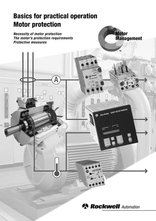
  • 1. Basics for practical operation Motor protection Necessity of motor protection Motor The motor’s protection requirements Management Protective measures TM
  • 2.
  • 3. Foreword This technical manual for “Motor Protection” is another publication on the subject of “Motor Management”. With these fundamentals, published at regular intervals, the user will have a growing reference work on the performance and operational data required for design and application. Topics covered include: • Motor Starting • Selection and Operation of Switchgear • Communications. The following manuals have already been published • “Three-phase Induction Motors” - informs about structure, modes, selection and dimensioning of motors • “Basics of Power Circuit Breakers” - additional information for the practical use of Power Circuit Breakers. Electric motors can be found in every production process today. The optimal use of the drives is becoming increasingly important in order to ensure cost-effective operations. “ Motor Management” from Rockwell Automation will help you: • to optimise the use of your systems • to reduce maintenance costs • to increase operational safety. We are pleased that our publications may help you find economical and efficient solutions for your applications. Copyright © 1997 by Rockwell Automation AG All information given represents the current level of technology available and is not legally binding. i
  • 4. Motor protection Table of contents 1 Necessity of motor protection 1.1 2 The motor’s protection requirements 2.1 2.1 Temperature Rise 2.1 2.1.1 Operational behaviour 2.1 2.1.2 Limiting temperature and insulation classes 2.3 2.1.3 Insulation ageing 2.4 2.1.4 Response limits 2.5 2.1.5 Phase failure 2.6 2.1.6 Asymmetry in the network 2.8 2.1.7 Earth fault 2.9 2.1.8 Short circuit 2.9 3 The system’s protection requirements 3.1 3.1 Stalling 3.1 3.2 Underload 3.1 3.3 Incorrect rotation 3.1 3.4 Motors in explosion-risk areas 3.1 3.4.1 Ignition protection type and increased safety EEx e 3.1 3.4.2 Significance of time tE 3.2 4 Protection measures 4.1 5 Temperature-dependent protection measures 5.1 5.1 Application problems 5.1 5.1.1 Applications 5.1 5.1.2 Thermal inertia 5.1 5.2 Bimetallic sensors in the winding 5.2 5.3 PTC - sensors 5.3 5.4 Linear temperature sensors 5.4 ii
  • 5. Motor protection 6 Current-dependent protection 6.1 6.1 Function 6.1 6.2 Device characteristics 6.1 6.2.1 Stationary operation 6.1 6.2.2 Intermittent operation 6.2 6.3 Bimetallic protection principle 6.3 6.3.1 Function 6.3 6.3.2 Short circuit resistance 6.5 6.3.3 Single-phase operation 6.5 6.3.4 Phase failure 6.5 6.3.5 Recovery time 6.7 6.3.6 Current setting 6.8 6.3.7 Trip Free 6.9 6.4 Motor protection during heavy duty starting 6.9 6.5 Motor protection in hazardous area locations 6.10 6.6 Electronic motor protection 6.10 6.6.1 Overload protection 6.11 6.6.1.1 Thermal projection models 6.11 6.6.1.2 Current setting 6.12 6.6.1.3 Setting the tripping time 6.13 6.6.2 Special motor protection functions 6.14 6.6.2.1 Phase failure 6.14 6.6.2.2 Asymmetry 6.14 6.6.2.3 Short-to-earth 6.15 Short-to-earth using the “Holmgreen”- method (rigidly earthed networks) 6.15 Short-to-earth using cumulative current transformers 6.16 Leakage protection in medium voltage networks 6.16 6.6.2.4 Short-circuit protection of medium voltage motors 6.21 6.6.3 System-protection functions 6.22 6.6.3.1 High overload and stalling 6.22 6.6.3.2 Underload 6.23 6.6.3.3 Incorrect rotation protection 6.24 6.6.3.4 Start time monitoring 6.24 6.6.3.5 Stalling during start 6.25 6.6.4 Control functions 6.26 6.6.4.1 Pre-warning 6.26 6.6.4.2 Load control 6.26 6.6.4.3 Start lock-out 6.26 6.6.4.4 Star-delta-change-over 6.27 6.6.4.5 Warm start 6.28 6.6.4.6 Possibilities for communication 6.29 iii
  • 6. Motor protection 6.6.5 Applications of electronic motor overloads 6.29 6.6.5.1 Low thermal inertia motors 6.29 6.6.5.2 High thermal inertia motors 6.30 6.6.5.3 Rotorcritical motors 6.30 6.6.5.4 Medium voltage motors 6.30 6.6.5.5 Slip-ring motors 6.31 6.6.5.6 Multi-stage motors 6.31 6.6.5.7 Frequency-controlled motors 6.32 6.6.5.8 Soft start 6.32 6.6.5.9 Motors with remote ventilation 6.33 6.6.5.10 Increased ambient temperature 6.33 6.6.5.11 Motors in hazardous locations 6.33 6.6.5.12 Protection of compensated motors 6.34 7 Selecting the correct motor overload 7.1 7.1 Application-dependent selection 7.2 7.2 Selection depending on motor and drive 7.3 7.3 Selection depending on ambient conditions 7.4 7.4 Selection in accordance with motor management criteria 7.5 iv
  • 7. Motor protection 1 Necessity for motor protection It could be assumed that properly planned, dimensioned, installed, operated and maintained drives should not break down. In real life, however, these conditions are hardly ever ideal. The frequency of different motor damage differs since it depends on different specific operating conditions. Statistics show that annual down times of 0.5...4% have to be expected. Most breakdowns are caused by an overload. Insulation faults leading to earth faults, turn-to-turn or winding short circuits are caused by excess voltage or contamination by dampness, oil, grease, dust or chemicals. The approximate percentages of by these individual faults are: • overload 30% • insulation damage 20% • phase failure 14% • bearing damage 13% • ageing 10% • rotor damage 5% • others 8% Therefore, the following points must be observed to guarantee fault-free operation of an electrical drive: • Correct design: a suitable motor has to be selected for each application. • Professional operation: professional installation and regular maintenance are preconditions for fault-free operation. • Good motor protection: this has to cover all possible problem areas. - It must not be tripped before the motor is put at risk. - If the motor is put at risk, the protection device has to operate before any damage occurs. - If damage cannot be prevented, the protection device has to operate quickly in order to restrict the extent of the damage as much as possible. 1.1
  • 8. Motor protection Table 1.2.1 represents a summary of the most frequent breakdown causes for motors, their extent and the possible damage caused. Cause Effect Possible damage Thermal overload: • extreme starting conditions overcurrent and soldered joint damage • locked rotor thus unacceptable rotor cage • high overload heating-up burnt windings • undervoltage of windings stator windings • intermittent operation Cooling problems: • restricted cooling unacceptable burnt windings • ambient temperature too high heating-up stator windings Electrical causes: • single phase conditions unbalanced individual windings • unbalanced voltage overcurrent of or parts burnt • earth fault windings heating-up • shorted turns depending on motor • winding short circuit size and bearing damage load Mechanical causes: • imbalance uneven wear of bearing damage • mis-alignment bearings • improperly installed drive (e.g., bearing load of V-belts too high) Tab. 1.2.1 Breakdown causes, effects and possible motor damage. 1.2
  • 9. Motor protection 2 The motor’s protection requirements 2.1 Temperature Rise In line with applicable standards, every motor manufacturer guarantees that critical machine parts remain within the permissible temperature range during rated operation and that short-term overloads do not damage the motor. The motor protection device, on the one hand, has to allow full use and thus the efficient operation of the motor and, on the other hand, react quickly enough in case of an overload. 2.1.1 Operational behaviour Electrical motors are energy transformers. They take in electrical energy and transform it into mechanical energy. This process causes energy losses, which takes the form of heat. The total energy loss comprises of two components: • Current-independent losses: they are practically constant, this means they also occur at no-load. - core losses caused by polarity changes and eddy currents - mechanical losses caused by friction and aeration • Current-dependent losses: they increase with load, i.e. with increased current. - I2R losses in the stator - I2R losses in the rotor The power loss increases approximately in proportion to the square of the current . The latter is almost proportional to the motor’s slip. According to Figure 2.2.1, for a stalled , static rotor, the maximum starting current in the stator is 4...8 In. The total input power is transformed into heat. If the rotor remains stalled, the temperature of the stator and rotor winding increases considerably, as part of the heat can only flow into the motor casing after a delay. If the motor is not switched off in time, the stator and rotor winding can burn out The heat losses generated reduce with increased speed. After run-up, the temperature increases further in an e-function, as shown in Figure 2.2.2, until it reaches final temperature level. For a higher load, the final temperature will be correspondingly higher. 2.1
  • 10. Motor protection I I I I Fig. 2.2.1 Squirrel-cage motor started direct on line (DOL). During starting time tA, a high motor starting current IA flows. It does not cause excessive heating if the starting time remains below the limit specified by the motor manufacturer, which is usually 10 sec. The short-term, unbalanced starting current peak can be ignored. ϑ ϑG insulation temperature limit (class of motor) ϑG ϑe ϑK coolant temperature ϑs tA starting time ϑS temperature increase during start ϑe temperature increase during ϑK continuous operation with rated current Ie t tB Stalling time 0t t A B Fig. 2.2.2 Temperature increase in the motor winding Due to the high starting current IA, the winding’s temperature increases during starting time tA very quickly. After the start, the temperature drops temporarily, as heat is transferred to the motor body. If the rotor remains stalled, the windings reach their temperature limits very quickly. Electrical motors are thermally non-homogenous systems. The windings, stator iron and rotor have a different heat capacity and heat conductivity. After start and during load changes, a temperature compensation takes place between the different machine parts. The heat flows from the hot winding to the cooler iron until a temperature balance has been achieved. 2.2
  • 11. Motor protection 2.1.2 Limiting temperature and insulation classes The limiting temperatures of the windings and, thus the permissible motor load are above all determined by the winding insulation. The IEC-recommendations for electrical machines (IEC 34-1 and IEC 85), as well as Regulation VDE 0530 Part 1, have been listed in Table 2.3.1. A difference is made between: • Max. coolant temperature: the motor can achieve its rated power at this temperature. • Limiting temperature in K is the average value from resistance measurements. The winding temperature is the sum of the coolant temperature and the winding warm-up. If the coolant temperature is below 40 ºC, the motor load can be increased. If it exceeds 40 ºC, the load has to be reduced. • Highest permissible permanent temperature in ºC for the hottest winding spot. Insulation Max. coolant Temp. over Highest permissible class temp. in ºC limit in K constant temp. in ºC E 40 75 120 B 40 80 130 F 40 105 155 H 40 125 180 Tab. 2.3.1 Insulation material classes and highest permissible constant winding temperatur The highest permissible constant temperature of individual insulation materials comprises of coolant temperature, temperature over limit and a heating-up tolerance. The latter is a safety factor, since the temperature measurement by ohmic resistance does not establish the hottest winding spot. For very high ambient temperatures, motors with specially heat-resistant insulation are produced. These machines can also achieve their rated power at high coolant temperatures. By far the most widespread cooling type is self-ventilation with ambient air. By means of a shaft-mounted fan, self-cooled motors guide an airstream over the housing surface. This means that the coolant - air - has the same temperature as the area immediately surrounding the motor. The cooling power depends on the motor speed. Due to their simple structure (no insulation), ordinary squirrel-cage motor rotors do not have a critical temperature. Therefore, they are permitted to reach a higher temperature constantly. 2.3
  • 12. Motor protection Problems can occur during the starting of medium voltage and larger low voltage motors, since the value of the losses can limit the starting time. The starting time and the permissible stalling time are therefore limited by the rotor’s heat capacity. These motors are called “rotor critical” motors. The high temperature increase can lead to mechanical tensions and result in an de-soldering of rotor rods. For motors with protection type “increased protection - EEx e”, the increased temperature can serve as an ignition source. 2.1.3 Insulation ageing If the temperature limit is adhered to, the winding life time for all insulation classes can be estimated at 100,000 h. This corresponds to approximately 12 year of continuous operation at rated power. Insulation ageing is a chemical process, which is highly temperature-dependent as shown in Fig. 2.4.1. Due to heating up, part of the insulation material evaporates, which leads to an increasing porosity and, as a result of this, a decreased voltage resistance. The following rule applies: if the operating temperature exceeds the highest permissible temperature by 10K, the life span reduces by half. Short-term excessively high temperatures do not have a considerable impact on a motor’s life span. The continuous operating temperature, however, must not exceed the highest permissible value. t Life span ϑ Temperature rise Figure 2.4.1 Reduction of an average motor winding life span due to excessively high temperature. 2.4
  • 13. Motor protection Modern design methods take the motor’s overload-situations into consideration. This makes it possible to make full use of the life cycle reserve. This is called life- cycle oriented design, which has the aim to enable motor operation for as long as the motor has to operate for economic reasons. 2.1.4 Response limits In order to guarantee the protection of standard motors, the IEC has established response limits for time-delayed overload-relays. Values according to IEC 947-4-1 apply to temperature-compensated, balanced pole load overload relays adjusted to the rated operating current. Figure 2.5.1 and Table 2.5.1. I overload as a multiple of the set current value ϑ ambient temperature IEC limiting values according to IEC 947-4-1 Figure 2.5.1 Current multiple limiting-values for temperature-compensated overload-relays acc. to IEC 947-4-1. Function should not to respond to respond to respond respond after following from warm from cold from cold current increase Multiple of the 1.05 1.2 1.5 7.2 set current value Response 10 A ≥2h <2h < 2 min 2…10 s time acc. to 10 ≥2h <2h < 4 min. 4…10 s response 20 ≥2h <2h < 8 min. 6…20 s class: 30 ≥2h <2h < 12 min. 9…30 s Tab. 2.5.1 Response limits at +20 ºC and balanced pole load for ambient temperature-compensated, thermal, overload relays acc. to IEC 947-4-1. 2.5
  • 14. Motor protection For a two-pole load on three-pole thermal overload-relays (e.g., for failure of a phase), the response limits listed in Table 2.6.1. apply. 2.1.5 Phase failure Type of thermal Multiple of set current Ambient overload-relay value environment response response temperature t > 2 h, t≤2h based on cold condition of relay ambient temperature compensated 3 Poles 1.0 2 Poles 1.32 + 20 ºC not sensitive to phase failure 1 Poles 0 not ambient temperature compensated 3 Poles 1.0 2 Poles 1.25 + 40 ºC not sensitive to phase failure 1 Poles 0 ambient temperature compensated 2 Poles 1.0 2 Poles 1.15 + 20 ºC sensitive to phase failure 1 Pole 0.9 1 Pole 0 Tab. 2.6.1 Response limits for three-pole thermal overload-relays with two-pole load only. 2.1.5 Phase failure A phase failure is an interruption of a single conductor. The motor then continues running with two phases and can suffer damage. The cause is, for example, blown fuse. Small to medium-sized motors are mostly stator-critical - this means that only the stator can be damaged. It has to be differentiated between: • Motors in star connection: these motors are not put at risk by a phase failure. As shown in Fig. 2.7.1, the currents in the motor windings, during disturbed and undisturbed operation at the failure of a single conductor, equal the currents in the other two. Due to the increasing current, a higher power loss occurs in both live windings. On the whole, the motor is running cool, since the third cold winding causes a temperature compensation. In case of an over- current, a protective current detector trips in time. Small to medium-sized (stator-critical) motors in star connection are usually not put at risk during a phase failure. • Motors in delta connection: In delta connection, the phase currents in undisturbed operation are lower by a factor 1/√3 than the currents in the windings ISTR = 0.58 In. During the failure of a phase, the current increases for electromagnetic reasons by approximately 50%, as shown in Fig. 2.7.2. In the other two windings, which are now switched in series, the current falls to 2.6
  • 15. Motor protection approximately 67%. This phenomenon occurs because the motor keeps the power transmitted to the shaft practically constant. The absolute current increase in the windings and in both intact phases depends on the load applied. Ie IStr Currents in the phases and windings in undisturbed operation. Ie1 IStr1 Currents in the phases and windings in disturbed operation. Fig. 2.7.1 Phase failure of a motor in star connection. Current flow in undisturbed and disturbed operation. IL IStr Currents in the phases and windings in undisturbed operation. IL1 IStr1 IStr2 Currents in the phases and windings in disturbed operation. Fig. 2.7.2 Phase failure of a motor in delta connection. Current flow during undisturbed and disturbed operation as function of the load. 2.7
  • 16. Motor protection Since the currents in the windings are not equal, they do not warm up equally either. Since heat is exchanged between individual windings and between windings and the iron body, the warming up of the stator is proportional to the sum of all losses in all windings. In general, the following applies for motors with an output of: - Pe ≤ 10kW: they do not require a special phase failure protection, as long as the two-phase trip current is ≤ 1.25 Ie . In this case, the warming up is, at the most equal, to the warming up during a symmetrical, three-phase load. - Pe ≥ 10 kW: for these motors, a motor protector with phase failure protection or a quick-response electronic protector is recommended. Besides electrical protection, the fast cut-out also contributes to reduced stress on the bearings. Many companies and electricity company’s factory regulations demand phase-failure sensitive motor protection mainly for bigger drives, or for systems with an increased safety requirement. For a single-phase feed of the stator, the rotor losses are considerably higher compared to a symmetrical feed. This can represent an additional danger, especially for rotor-critical motors. 2.1.6 Asymmetry in the network The voltage between lines, as well as the phase voltage in the induction net, are not exactly the same. Causes can be, for example: • very long mains supply lines • defective contacts on power-circuit breakers and contactors • loose terminal connections IEC and NEMA define the voltage asymmetry like this: ∆U (%) = Maximum deviation from the average of the phase voltages x 100 average of phase voltages The current asymmetry of the winding currents resulting from the voltage deviations amounts to 6...10fold of the voltage asymmetry and causes an additional heating up and reduction of the motor’s life span. Fig. 2.9.1 shows the reduction factors for the motor output according to IEC and NEMA. 2.8
  • 17. Motor protection fR reduction factor for motor output ∆U voltage asymmetry [%] ∆ Fig. 2.9.1 Power reduction as a result of voltage asymmetry. 2.1.7 Earth fault Insulation damage usually results from high voltage surges and often leads to shorts against earthed machine parts. Sources of these discharges are lightning strikes, network switches, capacitor discharges and the operation of power engineering systems. 2.1.8 Short circuit A difference is made between single-pole shorts against earth and two- and three- pole short circuits with and without earth contact. The main causes for these short circuits are insulation damage and mechanical damage. The currents depend on the circuit’s impedance and can reach high values. As the duration of the short circuit increases, the material damage also increases. Therefore, short circuits should be detected quickly and switched off. 2.9
  • 19. Motor protection 3 The system’s protection requirements 3.1 Stalling An excessive load torque or mechanical damage can cause a drive to be stalled. It is advisable to disconnect the drive affected as quickly as possible from the network. By doing this, any unnecessary mechanical and thermal strain on the motor and power transmission elements is avoided. In general, the number of possible accidents can also be reduced. 3.2 Underload Dangers from underload and a correspondingly low current take-in are possible when motors are cooled by the pumped medium itself. Problems can, for example, occur for ventilators or underwater pumps by a lack of, or insufficient, pumping volume due to blocked filters of closed valves. The drives can overheat despite being underloaded. Such machines can usually be found in inaccessible locations, like pumps in boreholes, which can result in costly repairs when damage occurs. Occurrence of an underload during a low current can also point to a mechanical fault. Examples for this are defective couplings, broken shafts, torn transport belts, damaged ventilator blades, etc. Such underload situations do not represent a danger to the motor, They do, however, cause plant down times and can lead to system damage. Quick fault detection helps reduce down times and possible accidents. 3.3 Incorrect rotation Switching on a drive with the incorrect rotation can severely damage a system and is often linked to high accident probability. For mobile systems, such as construction machines, cooling transporters etc., the incorrect rotation has to be expected following repairs or work carried out on the electrical distribution network. Switching on these drives, which have the incorrect rotation, has to be avoided. 3.4 Motors in explosion-risk areas 3.4.1 Ignition protection type and increased safety EEx e Under certain conditions, mixtures of ignitable gases and vapours and air can be ignited by sparks or high temperatures. The ignition temperature depends on the mixture’s chemical composition and the mixing ratio. The ignition of a mixture, which could explode, can be avoided for motors if it is ensured that the maximum temperature of the hottest spot lies below the lowest critical ignition temperature for that area. The limiting temperature of the winding insulation must, of course, not be exceeded. 3.1
  • 20. Motor protection 3.4.2 Significance of time tE The time tE is, according to Figure 3.2.1, the period of time which passes when the motor is warmed up from the rated operational temperature to the permissible limiting temperature. It is calculated for the most unfavourable case, i.e. for a stalled rotor and the highest permissible ambient temperature. Therefore, a motor protection device has to switch off the motor during starting current IA (highest value for stalled rotor) within time tE. This means that the motor does not reach the critical temperature. Figure 3.2.1 Definition of time tE, within which a motor with a stalled rotor warms up from its rated operational temperature to its limiting temperature. ϑ Temperature ϑA The motor’s highest permissible ambient temperature ϑe Rated operational temperature ϑG Limiting temperature t Time 1 Temperature Rise during rated operation 2 Temperature Rise with stalled motor For countries with a general test requirement, the time/current curve is automatically included. Only devices which have been checked in this way can be used in theses countries to protect EEx e motors. 3.2
  • 21. Motor protection 4 Protection measures For motor temperature control, the following two methods, which complement each other, are used: • Temperature measurement with sensors installed in the stator winding: the sensor measures the temperature directly in front of the motor winding, but only at the location where it has been fitted. In addition to this, the sensor’s thermal delay, often exceeds 10s, this has to be considered. The following are not measured: - rotor overload - phase failure - asymmetry - short circuit - earth fault • Current measurement in supply line: a current measurement in the supply line is useful if the motor’s temperature increase is known as a function of the motor current. The protection devices can be adjusted in accordance with the rated operating current and for brief overload situations. 4.1
  • 23. Motor protection 5. Temperature-dependent protection measures 5.1 Application problems 5.1.1 Applications The temperature sensors are installed in the stator winding shoulder. Therefore, they measure the motor’s critical temperature directly. Temperature sensors are mainly used under the following operating conditions: • changing load • start - stop - operation • countercurrent braking • high ambient temperature • poor cooling, for example, in dusty surroundings • speed-controlled motors. For different applications, the temperature sensor alone provides insufficient or even no protection at all. In these cases, additional current-measuring protectors are used. This is necessary for: • rotor-critical motors • protection in case of - earth failure - short circuit - a locked rotor - Motors with low thermal inertia • quick reaction in case of phase failure and asymmetry. 5.1.2 Thermal inertia For motors with low thermal inertia like thermally encapsulated refrigeration motors or underwater pump drives, the thermal delay between winding and sensor can prove critical. The interaction time is, depending on the type of sensor and its installation into the winding, within 10s. Fast temperature changes represent a protection problem. During continuous operation, winding and sensor have practically the same temperature. During start or large load changes as is the case, for example, with a locked rotor, the winding temperature increases very quickly. The sensor temperature follows in line with the interaction time constant shown in Figure 5.2.1. 5.1
  • 24. Motor protection Due to the sensor’s interaction time constant, an insulation class B winding has already reached a temperature of ∆ϑ = 180 K above the coolant temperature of 40 º C when the sensor reaches the temperature limit. ∆ϑ temperature difference above the coolant temperature of 40 º C ϑM development of winding temperature for a motor with a temperature increase of 15 K/s ϑF development of sensor temperature ϑG limiting temperature for insulation class B t time in s Fig. 5.2.1 Thermal delay of a PTC sensor integrated into the stator winding. For example, during the stalling of an underwater motor, the current density in the stator winding can reach up to 50 A/mm2. In this case, the winding temperature increases rapidly at approximately 15 K/s. When the sensor with an interaction time constant of 8s reaches the permissible temperature limit for insulation class B, the winding temperature has already reached more than 180 K above the coolant temperature of 40º C. The motor can be at risk. 5.2 Bimetallic sensors in the winding Bimetallic sensors consist of two metals with different thermal expansion coefficients rolled on top of each other. If they are warmed up, they expand unevenly and can trigger a switch contact. They have the advantage that the control voltage can, in principle, be directly applied to the switch, which makes a special tripping mechanism unnecessary. The following disadvantages, however, restrict their application: • long thermal delay • restricted accuracy. The tripping temperature can be affected by careless fitting. • large size compared to modern sensors. 5.2
  • 25. Motor protection 5.3 PTC-sensors The sensor most commonly used in low voltage motors is the thermistor with positive temperature coefficient (PTC). These PTC-resistors are also referred to as thermistors. The miniaturised sensors (Figure 5.3.1) have a low resistance below the rated response temperature, and increase their resistance in the rated response temperatures range, as shown in Figure 5.4.1, by several ranges. This resistance change is evaluated by means of a tripping device. The rated response temperature is defined by the PTC - sensor and thus is independent of the tripping device. a PTC-sensor (thermistor) b soldering point c sensor insulation d winding insulation e sensor-connection wires f winding wires g wire insulation A, B, C Direction of heat flow Fig. 5.3.1 Cross-section of a PTC sensor and a low voltage motor winding The sensors are installed into the motor’s winding shoulder from the discharge airside, and the rated response temperature TNF is allocated to the corresponding insulation class. The sensor’s response can be used to switch off the motor switch or for detection. If a warning is to occur before the critical temperature has been reached, further sensors with a lower rated response temperature have to be installed. 5.3
  • 26. Motor protection R resistance in sensor 4,000 circuit in Ω 1,330 ϑ temperature TNF rated response 550 temperature tolerance 250 limit in ºC defined cutoff values 100 Ω ° ° Fig. 5.4.1 Characteristic resistance-temperature curve of a PTC-sensor in line with IEC 34-11-2. 5.4 Linear temperature sensors Pt 100 platinum sensors are normally used as linear temperature sensors. The resistance value changes in proportion to the temperature. As shown in Figure 5.4.2, at 0 º C Pt 100-sensors have a resistance of 100Ω. They are predominantly used in large motors. Medium-voltage motors usually have Pt 100 - sensors incorporated as standard. ϑ temperature [º C] R resistance [Ω] Figure 5.4.2 Characteristic resistance curve of a Pt 100-sensor. Contrary to the PTC-sensor, whose rated response temperature is determined by the sensor, the Pt 100-sensor’s response temperature can be freely adjusted on the tripping device. In addition to this, every possible temperature value can be picked up for pre-warning, restart locking or load control. Ni 100 -, Ni 120 - and Cu 10 - sensors are rarely used. 5.4
  • 27. Motor protection 6 Current-dependent protection 6.1 Function The motor’s current consumption is a measurement of its temperature rise. Since the temperature in the stator winding or the rotor body is not measured, this connection only applies if the following marginal conditions are adhered to: • the motor’s rated load refers to the maximum coolant temperature of 40 º C. • temporary overloads, for example, during start, have to be tolerated by the overload as shown in Figure 6.1.1. M motor start characteristics F tripping characteristics of a bimetallic trip IAmax starting current Ie rated current tA starting time [s] Fig. 6.1.1 Motor overloads must permit the motor to start. The characteristic device curve F must always stay above the characteristic motor curve M For protection systems, which detect currents, the problems and restrictions discussed for temperature sensors do not apply. 6.2 Device characteristics 6.2.1 Stationary operation During stationary operation, exceeding the limiting temperature as shown in Fig. 6.2.1 can also be prevented by means of a simple protective device whose warm- up curves do not correspond to those of the motor. It is a precondition is that the protector is thermally equally as fast or faster than the motor. 6.1
  • 28. Motor protection Fig. 6.2.1 Temperature Rise characteristics of a motor and thermal protector for a low overload during continuous operation. M thermal motor curve F1, F2 fast motor protection devices: motor is protected against overload F3 slow motor protection device: motor can heat up to impermissible value during overload ϑ temperature ϑIe temperature during rated operation t time • Tripping device faster than motor temperature riser curve: the motor is protected against an overload. The protection device trips too early and prevents full use of the motor. • Tripping device slower than motor temperature rise curve: The motor can heat up to an impermissible value. By means of high-quality motor protection devices (chapter 6.6), the motor temperature rise curve can be projected accurately. Despite maximum use, the motor is safely protected. 6.2.2 Intermittent operation During constant load or one-off motor warm-up, the thermal conditions are relatively easy. During changing operating conditions, however, e.g., during periodic duty, it is very important that the motor and the protector share the same transient condition. Figure 6.3.1 shows how the different characteristic curves diverge. During intermittent operation, the winding’s temperature, compared to that of the iron, changes rather drastically. For cycle times under 5...10 min the latter remains practically constant. In addition to this, the cooling conditions of self-ventilated motors during run and standstill differ quite considerably. The cooling time constant is approximately 2...5 times longer than the warming-up time constant. Bimetallic and simple electronic protective devices do not take this fact into consideration. 6.2
  • 29. Motor protection Figure 6.3.1 Temperature Rise and cooling characteristics of motor and thermal relay during intermittent load 1 Temperature Rise characteristics of motor and thermal relay 2 cooling characteristics of motor 3 cooling characteristics of a thermal relay, without taking different cooling conditions during run and standstill into consideration 4 development of winding temperature in the motor 5 development of winding temperature projected by thermal relay ϑIe temperature during rated operation t time The transient behaviour of different motors is not the same. Nevertheless, protective devices should project the motor’s temperature behaviour as accurately as possible. In most cases, a compromise is necessary, resulting in a slightly overprotected motor. Also during intermittent operation, the electronic protection devices mentioned in Chapter 6.6 can allow maximum motor use. 6.3 Bimetallic - Protection principle 6.3.1 Function Thermally delayed overload-relays and the overload protection of most power circuit breakers use bimetallic strips, which are heated by the motor current. As shown in Figure 6.4.1, the bimetals trigger an auxiliary contact via a trip bar, which interrupts the motor contactor’s coil circuit. For power circuit breakers direct tripping occurs. The following heating types can be distinguished according to Figure 6.4.2: • Direct heating: the heating current of approximately 20...70 A flows directly through the bimetallic strip. Lower currents are not permissible, since their heating capacity (Pv = I2 R) is insufficient for deflection. • Indirect heating: the current does not flow through the bimetal itself but through a heater winding which is coiled around the bimetallic strip. They are suitable for currents of approximately 0.1...20 A. 6.3
  • 30. Motor protection A indirectly heated bimetals B trip gate C trip lever D moved contact E compensation bimetal Fig. 6.4.1 Functional principle of a three-pole, thermally delayed thermal relay with temperature compensation. In accordance with IEC, the temperature compensation takes place between -5 ºC +40 ºC. • Transformer heating: the motor current (> 60 A) flows through a transformer’s primary winding. The bimetal’s heating winding is connected at the secondary side. In case of a short circuit, the bimetallic relay is practically fully protected. A high expansion alloy B low expansion alloy C deformation caused by heating up D anchor Fig. 6.4.2 Properties of heated bimetals. a direct heating b indirect heating c transformer heating (transducer relay) 6.4
  • 31. Motor protection Thermal relays are mostly temperature-compensated. An additional compensation bimetal in the power transmission path from the current-bimetal to the trip contact prevents the relay’s tripping characteristics from changing - as a result of the ambient temperature which acc. to the IEC lies between -5...+40 ºC, and adversely affecting the protected object. Since the permissible motor load reduces with increasing coolant temperature, the relays are often slightly under-compensated for safety reasons. During the start followed by constant load, the thermal relay protects the motor without any problems. During intermittent operation with high switch frequency and changing load, however, motor protection is only insufficient, since the thermal relay can only approximately reproduce the motor’s thermal behaviour. During frequent starts in intermittent operation, the bimetal's time constant, which is considerably shorter compared to the motor’s, causes a premature trip. This means that the motor’s thermal capacity cannot be fully used. In addition to this, the thermal relay’s cooling time constant is shorter. This means that, during intermittent operation, the difference between the motor’s temperature and the thermal relay’s simulation increases constantly. Fig. 6.3.1. 6.3.2 Short circuit resistance For thermal reasons, the short circuit resistance of directly heated thermal relays is higher than for indirectly heated relays. During high rated currents, thermal relays are therefore operated via current transformers. They provide short circuit resistance up to the highest currents. The following short circuit resistance values apply for the current IeF, adjusted at the thermal relay: • indirectly heated thermal relays up to 16 IeF max • directly heated thermal relays up to 30 IeF max • current transformer thermal relays up to 50 IeF max 6.3.3 Single-phase operation The power required for tripping the switch mechanism can only be generated by three bimetallic strips together. The three bimetallic relays have to be switched in series, as shown in Figure 6.6.1, to ensure that a current also flows through them during single-phase operation. 6.3.4 Phase failure Motors in star connection are not thermally at risk if a phase fails. For motors in delta connection, the following differences have to be made between: • rated output Pe ≤ 10 kW: the thermal relay’s single-phase starting current should amount to ≤ 1.25 Ie 6.5
  • 32. Motor protection Fig. 6.6.1 Series circuit of thermal relay bimetals during single-phase operation. • rated output Pe ≥ 10 kW: the motor protectors should be equipped with a differential trigger. The resource regulations of various industries require differential triggers, for example the chemical, petrochemical and gas industries. Tripping during a three- phase overload Tripping during failure of a phase with unheated, medium bimetal Fig. 6.6.2 Differential tripping principle for thermal relays 1 bimetallic strip 4 differential lever 2 failure gate 5 tripping contact (spring-loaded contact) 3 overload gate S1 tripping motion during overload S2 tripping motion during phase failure S3 opening of tripping contact 6.6
  • 33. Motor protection As shown in Figure 6.6.2, a double gate arrangement consisting of a failure gate and an overload gate forms the basis of differential tripping. During phase failure, the dead, cooling bimetal moves the failure gate in the opposite direction to the overload gate. This reciprocal motion is transformed into an additional tripping motion by a differential lever. During phase failure, this double gate arrangement causes tripping at 85% of the three-phase tripping current. This refers to the current flowing through the thermal relay. When the motors are switched in delta and during phase failure, the currents in the thermal relay and the motor windings differ. The current distribution in the motor is also not constant but load-dependent. Fig. 6.7.1 shows the typical characteristic tripping curve of a thermal relay with and without differential trigger for cold or warm condition. Ie tripping current t tripping time [s] seconds [m] minutes From cold: a symmetrical 3pole load b 2pole load with differential trip c 2pole load without differential trip From warm: d symmetrical 3pole load Fig. 6.7.1 Typical characteristic tripping curve of a thermal relay. 6.3.5 Recovery time After tripping, thermal relays require a certain period of time for the bimetal strips to cool down again. This period of time is termed recovery time. They can be reset only after this time has expired. The recovery time depends on the thermal relay’s tripping curve and the size of the current leading to tripping. Figure 6.8.1 shows the average values for thermal relays recovery time. It can be seen that, following tripping with a 4fold set current, the recovery time is approximately 35 s. 6.7
  • 34. Motor protection IeF set current tw recovery time [s] seconds [m] minutes Fig. 6.8.1 Guidance values for the recovery time of thermal relays The recovery time also serves the purpose of enabling the motor to cool down during this operational pause. This period of time is, however, in most cases insufficient to allow a re-start. 6.3.6 Current setting In general, the thermal relay has to be set to the rated current Ie. The scale dials of most protectors have one current range for direct start and another for star-delta start. The latter already has a factor of 1/√3 built in. If the coolant temperature exceeds 40 ºC, the motor power has to be reduced and the current setting has to be adapted to the thermal relay. If the motor manufacturer does not advise otherwise, Table 6.8.1. applies. Coolant temperature ºC 30 35 40 45 50 55 60 Correcting factor Ie 1.08 1.04 1 0.95 0.9 0.85 0.8 Tab. 6.8.1 Guidance values for correcting current setting factors on thermal relays for motors with deviating coolant temperature For installation heights which are over 1000 meters above sea-level, the permissible motor loads decrease and, therefore, so do the thermal relay settings. If the motor manufacturer does not advise otherwise, Table 6.9.1. comes into effect. Should deviating coolant temperatures occur at the same time as installation at great heights, the product of both factors has to be considered when setting the current at the thermal relay. 6.8
  • 35. Motor protection Installation height Factor for correction meters above sea level of rated output ≤ 1000 1.00 ≥ 1500 0.97 2000 0.94 2500 0.90 3000 0.86 3500 0.82 Tab. 6.9.1 Guidance values for rated output correction for a deviation in installation height. 6.3.7 Trip Free Mechanism “Trip Free” is required by the IEC and various national regulations. Tripping must also function if the reset key or the 0-key are pressed at the same time. The tripping mechanism is reset by pressing the reset key once more. With many thermal relays, the tripping mechanism also functions for automatic reset with blocked reset key. It is only possible to switch on again after the reset key has been pressed again. 6.4 Motor protection during heavy load start A motor’s starting current IA ≈ 4...8 Ie is not dependent on the load but on the motor design. The acceleration time tA however, is load-dependent. In accordance with Fig. 6.9.1, the term heavy load start is used if the acceleration time is dependent on the starting current and amounts to a few seconds. Under these conditions, a standard-thermal relay is placed under too much thermal strain and trips in most cases. t acceleration time Ie rated current N normal starting conditions S heavy load start Fig. 6.9.1 During heavy load start, the acceleration time is a function of the starting current and amounts to a few seconds. 6.9
  • 36. Motor protection For these cases, electronic motor overloads can be adapted exactly to the motor’s heavy load start (Chapter 6.6). Therefore, temporary circuits with thermal relays like saturation transducers, protective relay bridging during start and separate thermal relays for the start phase, are no longer required. 6.5 Motor protection in rooms with a risk of explosion Thermal relays for the protection of EEx e - motors have to comply with the standards and regulations outlined in Chapter 3.4. The thermal relays themselves are not explosion-protected and therefore must not be installed in the danger zone. In countries with a general test requirement, motor protectors for the protection of EEx e - motors can be used if the motor’s tE - time corresponds to the minimum values or is longer. If this is not the case, the motor’s tE - time must be compared with the characteristic tripping curves values in cold condition. Protection is guaranteed if the values at least correspond to the curve or even exceed it. In addition, it has to be checked for motors in delta connection whether the tripping time for two-pole tripping corresponds to the 0.87-fold of IA/Ie ≤ tE Electronic motor overloads (Chapter 6.6) permit the tE -time to be set exactly. This means that during a heavy load start, the permissible tE - time can be fully utilised. 6.6 Electronic motor protection Electronic motor overloads provide the possibility of projecting the thermal conditions within the motor for each operational type far more accurately than would be the case, for example, with thermal relays on bimetallic basis. At the same time, the newly acquired information helps to extend the protector’s application range. The main properties of electronic motor overloads are: • accurate current setting • improved protection for different start and operating conditions • extended protective, checking, monitoring and control functions. 6.10
  • 37. Motor protection 6.6.1 Overload protection 6.6.1.1 Thermal projection models With regard to accuracy, it is not important, in principle, whether the devices are implemented on an analogue or digital basis. These devices, which are equipped with microprocessors, are also partially suitable for communication with higher- order control systems and can, for example, be connected to bus systems. Depending on requirements, the devices are used in practice in accordance with the following models: • Single-body model: simple electronic motor overloads simulate motor warming only on the basis of a thermal single-body model. Their characteristic heating and cooling curves could be compared with thermal relay conditions. They only consider the stator winding’s heating capacity and, therefore, cool down too quickly during motor standstill, since the iron is not taken into consideration. Therefore, the motor has to be protected by additional thermal sensors during load changes and intermittent operation. • Two-body model: complex electronic motor overloads simulate the motor heating on the basis of a thermal two-body model. The simulation is based on a consideration of the stator winding’s heating and the motor’s iron mass. This helps, for example, to accurately project the fast heating of the winding during a heavy load start as well as the following heat transfer from motor winding to the iron, which heats up considerably more slowly. During running, the iron losses, as well as losses caused by asymmetry, are also fed into the simulation model. A consideration of the motor’s ambient temperature increases the maximum utilisation of the system, even during large temperature fluctuations. The different cooling conditions of a self-ventilated motor during run and standstill are taken into consideration by means of two different time constants. After switch-off, the winding’s rapid cooling-down to iron temperature and the subsequent slow cooling of the motor as a whole is projected. This means that the thermal projection of the electronic motor protector corresponds to the motor’s condition at all times. This enables maximum system utilisation and guarantees safe motor protection, even during difficult starting and operating conditions. The two-body simulation can be explained using a capacity-resistance network as shown in Fig. 6.12.1 6.11
  • 38. Motor protection P ≈ (I 2 + kI 2) Cu PFe M G R1 C1 S1 C2 U1 R2 R3 ϑ Umgeb Fig. 6.12.1 2-body projection to simulate motor warming. C1 capacity in accordance with the winding’s heat capacity (adjustable) C2 capacity in accordance with the heat capacity of the iron and other machine mass R1 resistance in accordance with the heat transfer resistance between winding and iron R2 resistance in accordance with heat losses to the environment during standstill R3 resistance in accordance with heat losses to the environment during run PCu feeding of a current in proportion to copper losses PFe feeding of a current in proportion to iron losses S1 change-over standstill/run IM motor current IG counter-component caused by asymmetry ϑUmgeb consideration of ambient-/cooling medium temperature with Pt 100-sensor. 6.6.1.2 Current setting Observing the permissible temperature for continuous motor operation ensures that the insulation’s life span is secured. For this reason, the correct current setting is very important. If the current were set too high, the protection of the machine could not be granted anymore. The setting has to reflect possible factors which deviate from normal conditions, like too high a coolant temperature, as shown in Table 6.8.1, or the installation of the motor above 1000 meters above sea level. See Table 6.9.1. With modern electronic motor overloads, the rated current is set directly and digitally in Amperes. If primary current transformers have been pre-switched, their ratio must also be considered. 6.12
  • 39. Motor protection The system in operation is also protected if the required lower operating current is set at the motor protector instead of the rated current. A higher load, e.g. through mechanical faults, is detected and the system can be switched off, as long as the damage is small. 6.6.1.3 Setting the tripping time By setting the tripping time, the electronic motor overload tripping characteristics are adapted to the motor’s thermal capacity. The optimal setting of the tripping time is possible if the motor’s permissible locked rotor from cold and its corresponding stalling current are known. See Fig. 6.13.1 Both values can be defined by the motor manufacturer. tA tripping time in sec Ie rated operating current of motor = IeF a locked rotor or maximum starting current; setting range, e.g., IA = 2.5…12 Ie b inertia; setting range with appropriately adjusted locked current, e.g., tIA = 1…600 sec I Fig. 6.13.1 Time-/Current curve of an electronic motor overload (from cold condition). In many cases, the permissible stalling time is unknown. But if the motor has been correctly dimensioned for the particular application, the following tripping times are recommended: • Standard motors: the normal setting is 10 s • Special motors, like thermally fast drives: one begins with a start trial with setting 2 s. If the motor overload trips, the motor is allowed to cool down. Then it starts again with the set 4 s and increases the trip time until the start is successful. 6.13
  • 40. Motor protection 6.6.2 Special motor protection functions 6.6.2.1 Phase failure Electronic motor overloads can recognise a phase failure independent of the load and can react immediately. Different solutions are used: • Differential trip: the tripping curve is shifted, similarly to the thermal relay, by means of an electronic differential trip. If the motor is not fully loaded, it can continue to run. • Fast cut out: this prevents unnecessary further heating up of the motor and protects motor and system bearings. The trip is often delayed by a short period of time in order to prevent an unnecessary cut out in the supply net during short, single-phase interruptions. 6.6.2.2 Asymmetry Asymmetrical phase voltages are mainly caused by long power lines. The resulting current asymmetry in the motor windings amounts, depending on the motor design, to 6...10-fold of the voltage asymmetry. Medium-sized and large low-voltage motors are quickly at risk thermally (rotor- critical motors). For this reason, the load must be reduced as shown in Fig. 2.9.1 in order to prevent the motor from overheating. Some electronic motor protection devices detect the asymmetry and correct the trip limit downwards. In practice, however, it is not always possible to reduce the motor load. The overload, however, can emit a warning signal. For asymmetrical feed, it is normally not only one motor but the entire system that is affected. It is therefore advisable to centrally control the mains voltage. In systems with a “bad” network with regularly asymmetrical mains voltage, the motors must be sized accordingly in order to prevent a negative effect on their life span. Higher asymmetries or the failure of a phase can be caused by defective contacts on power circuit breakers, contactors, terminals, failed fuses as well as by motor- internal faults. Fast detection and cut out prevent overheating damage on these devices. The system and motor bearings are protected. 6.14
  • 41. Motor protection Definition of voltage asymmetry in accordance with NEMA and IEC: ∆U (%) = Maximum deviation from the phase voltage average x 100 phase voltage average 6.6.2.3 Short-to-earth Insulation damage on motors is often caused by high voltage surges. Sources are lightning bolts, network changes, capacitor discharges and power electronics devices. Further causes are ageing, continuous or cyclical overloads, as well as mechanical vibrations and foreign bodies. Most insulation damage leads to shorts against earthed machine parts. In earthed networks, the earth currents can quickly reach high values. Depending on the network type and the requirement, the earth current has to be monitored using either the “Holmgreen” method or by means of a cumulative current transformer. Short-to-earth using the “Holmgreen” method (rigidly earthed networks) In order to detect a leakage current in rigid or low ohmic earthed networks, current in the three phase conductors are normally measured. For a healthy motor, the total of these currents equals zero. But if a current flows to the motor housing and thus into the earth, a residual current I0 occurs at the transducer star point, which is proportional to this earth current. It is detected by the leakage detector and causes a trip. A short delay prevents erroneous trips by transient transducer saturation which can occur during switching operations. A sensitivity must be chosen so that neither transducer transmission errors, nor interfering signals in start-delta connection caused by the third upper harmonics, can lead to false trips. Fig. 6.15.1 L1 L2 L3 1 3 5 MM 2 4 6 I0 M 3~ Fig. 6.15.1 Short-to-earth protection using the “Holmgreen” method T1 main current transformer MM motor protector I0 residual current (proportional to leakage current) 6.15
  • 42. Motor protection Short-to-earth using cumulative current transformers In insulated, high-impedance earthed or compensated networks, the high sensitivity required is achieved by means of a cumulative current transformer whose core covers all three conductors leading to the motor. In accordance with the leakage current-protector switch principle, sensitive protection against leakage is possible. If the response threshold is low, a small insulation defect is already sufficient to trigger an early warning or disconnection. Fig. 6.16.1. L1 L2 L3 1 3 5 T1 MM 2 4 6 K L T2 Σ M 3~ Fig. 6.16.1 Leakage protection using cumulative current transformer T1 main current transformer (2-phase current detection)| T2 cumulative current transformer MM motor overload Applications • medium-voltage motors • systems in difficult surroundings, for example, dampness, dust, etc., in mines, gravel quarries, cement factories, mills, wood processing, water pump works, water treatment plants, drainage Leakage protection in medium voltage networks The following passage aims to give an overview of the conditions for earth faults in insulated, high-impedance earthed or compensated networks. This overview is by no means exhaustive and does not consider transient effects. 6.16
  • 43. Motor protection For networks with the above-mentioned star-point earth types, the size of the earth fault current is determined by the networks earthing capacity and the earthing resistance or the compensating inductor. It is typical for relatively small industrial networks that the earth currents are very small. The earth capacity is mainly determined by cables and motors. The capacity values of cables can be found in cable tables, and are within the range of 0.2...1.2 µF per kilometre length. For medium voltage motors, a value of approx. 0.02...0.05 µF per megawatt motor output can be expected. It is a further general rule for industrial medium voltage networks that per 1000...1500 KVA system output approx. 1 Amp capacitive earth current can be expected. For the entire network to be monitored, a star point monitoring is carried out by measuring the translocation voltage. Leakage detectors in the motor branches help to locate the earth fault. In many cases, operation can be continued, as the earth currents which occur are relatively small and the insulation of the healthy phases can be operated with a higher voltage for a short period of time. Isolated or high-impedance earthed networks For symmetrical earth capacities, the star point of the undisturbed network assumes the earth potential and the total of the currents flowing via the earth capacitance is zero. Also the high-impedance earth resistance (Fig. 6.19.2/6.20.1/6.20.3) is cold for transformers with star points during normal operation. It prevents extreme overvoltages during intermittent earthing faults, which can occur in isolated networks. The rating is normally such that the resistor, during an earth fault, carries a current which is approximately as high as the networks capacitive charging current. If, for example, the pole conductor Fig. 6.19.1 and Fig. 6.19.3 is linked with the earth following an earth fault, the other two pole conductors lead a voltage between lines against earth. Through their earthing capacities CN (on network side, as seen from protector MM) and CM (on motor’s side), a capacitive current flows against earth and via the faulty area back to pole conductor 3. For a high-impedance earthing, Fig. 6.19.2/6.20.1/6.20.3, the voltage of the high star point drives an additional current across the faulty area, which is limited by the earth resistance. 6.17
  • 44. Motor protection In case of an earth fault on the measuring point’s network side (installation point of current transformers), the current protector MM measures the part of the earthing current flowing across CM. A response sensitivity must be selected which prevents the MM from tripping in this case. On the other hand, the MM should as accurately as possible, detect earth faults which occur, since for earth faults in the motor’s windings, the transitional voltage decreases the closer the fault point is to the star point. The leakage current decreases proportionally. Normally, the response threshold is not selected below 5...10 % of the current for a saturated earth fault on the motor terminals. Compensated networks Deleted networks, resonance earthing, compensation coil. Figures 6.19.2/6.20.1/6.20.3 also show the principal conditions for compensated industrial networks, although those are relatively rare. During full compensation, the compensation coil provides a current as high as the capacitive leakage current, but with reversed phase position, so that only the very low ohmic leakage current passes via the faulty area. Schematic representation of different network types and earthing positions The earth current measured by an electronic motor protector MM by means of a cumulative current transformer depends on the network type and the earthing position. The following diagrams show the conditions for different applications. Legend for following diagram: K1 contactor MM motor protector M1 motor CN earth capacity of pole conductors - network side CM earth capacity of motor, including cables between current transformer and motor L compensation coil R high-impedance earthing resistance T transformer IE earth leakage current 6.18