Streamlining Python Development: A Guide to a Modern Project Setup
08.20.24 kw.ongrid datasheet usl_06.05.2012
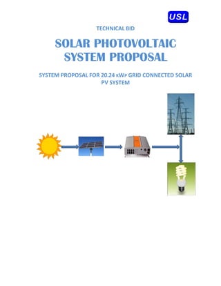
1. TECH
HNICAL BID
SO R PH OVO AIC
OLAR HOTO OLTA
SYST
S TEM PRO OSAL
OPO L
SYST
TEM PROPOSAL
L FOR 20 KWP GRID C
0.24 P CONNECT
TED SOLAR
L
PV
V SYSTEM
M
CUST
TOMER:
2. CONT
TENT
1.
SY
YSTEM DESIG
GN ...............................
...................
...................
............................................
2.
SY
YSTEM DESC
CRIPTION ......................
...................
..............................................................
3.
SY
YSTEM CONF
FIGURATION
N ................ ......................................................
................... .........
4.
BI
ILL OF MATE
ERIAL ............................
...................
...................
............................................
System P
Proposal – Page 2 of 11
3. 1. SY
YSTEM D
DESIGN
i. CUS
STOMER R
REQUIREM
MENT
The Customer wou like to in
uld nstall 20.24 kWp Grid c
connected S
Solar Power Plant in region of
South IIndia.
ii. DES
SIGN ASSU
UMPTIONS
S
Module Facing : True
e e South
Module Tilt angle : 14°
e
Type of
f System : Grid Connected System
iii. PRO
OPOSED TECHNOLOG
GY
The on‐
‐grid solar photovoltaic power plant to be proposed shall b
t be consisting of Poly crys
stalline
solar modules with fixed tilt a
m h ting systems and the solar inverters shall be of grid
angle mount s
interact
tive central t
type.
iv. BEN
NEFITS OF PROPOSED TECHNO
OLOGY
The ben
nefit of cryst
talline technology as com
mpared to other existing technologie is as fo llo
g es ows;
‐ It occupi less area when comp
ies pared to other thin film technologies
‐ Proven t
technology o
over years
rials to support high volu
‐ Abundan semiconductor mater
nt ume product
tion and
demand
d.
oduction facilities throug
‐ High volumes of pro
ghout world
v. ENERGY SIMU
ULATION R
RESULT
Based o the above inputs & assumption, an energy simulation h been carried out an the
on a has nd
results f
for the same
e are provide below.
ed
System P
Proposal – Page 3 of 11
4. vi. DES
SIGN SUMMARY
Total Installed capac
city : 20.2 Kwp
24
PV Modu
ule : 230W Crystalline Modules (K
Wp KL230)
Total Nu
umber of Mod
dules : 88 N
Numbers
String In
nverter : 5 kW
W
Total Nu
umber of Inve
erters : 4 No
os.
Approx yearly genera
ation / KWp : 1752 kwh /kwp / year
2.0 p
rox Yearly generation
** Appr : 35.4 MWh/ann
46 num**
Module T angle
Tilt : 14 D
Deg
Module orientation : True South
e
Area req
quired for mo
odule installat
tion : 150 Sq.mtrs.
** Note
e:
1. The above value
es are indicative
e for the location
n based on the historical radiatio
on data. The actu
ual data may var
ry
depending on th
he site condition
ns.
System P
Proposal – Page 4 of 11
5. 2. SY
YSTEM D
DESCRIPT
TION
i. Solar PV G
Grid Conne
ected Syste
em
A grid connected system is connected to a large independe
ent grid (ty
ypically the public
city grid) an feeds po
electric nd ower into t he grid. Th is a form of decentralized ele
his m ectricity
generat
tion. In the case of re
e esidential or building m
r mounted grid connected PV system the
d d ms,
electric demand of the build
city ding is met b the PV sy
by ystem. Only the excess is fed into t he grid
when t
there is an excess. The f
e feeding of e
electricity int the grid r
to requires the transformat
tion of
DC into
o AC by a spe
ecial, grid‐co
ontrolled inv
verter.
A grid‐t inverter o a (GTI) is a special ty of Invert (electrica that is us in a rene
tie or ype ter al) sed ewable
energy power syst
tem to conv
vert direct c
current into alternating current an feed it in the
nd nto
utility g
grid. The technical nam for a grid
me d‐tie inverte
er is "grid‐interactive in
nverter". The may
ey
also be called syn
e nchronous in
nverters. Gr
rid‐interactiv inverters typically cannot be u
ve s c used in
standalone applicat
tions where utility powe is not available.
er
The Delta Grid Tie S
Solar Inverte is designed to convert solar electric (photovoltaic or PV) p
er d power
into uti
ility‐grade electricity tha can be us by the h
at sed home or sold to the loca power com
d al mpany.
In orde
er to operat
te, the inver
rter must h
have grid po
ower availab
ble and connected. It w not
will
provide backup po
e ower if the AC grid fails. The invert will automatically sy
A ter ynchronize it
tself to
grid. Th
he inverter is
s provided w
with the isola
ation transfo
ormer internally with basic insulation.
System P
Proposal – Page 5 of 11
6. 3. SYSTEM
M CONFIG
GURATIO
ON
The maj
jor compone
ents of the p
proposed po
ower plant ar
re as follows
s:
Sl. No. Item
m Description
1 Module Cr
rystalline sola
ar modules ea ach of 230 W
Wp
2 Structure Fixed Mountinng
3 Inverter String inverter of 5Kw
4 Monitoring
g System Central
l Monitoring system
DC Combiner Box (DCCB)
5 Junction bo
ox
AC Dist tribution Box (ACDB)
6 Cables PVC Cu Cables
P s
Accessories fo cable inter
A or rconnection &
7 Accessories
s
installa
ation kit & co
onduits
8 Lightning Lightninng Protectionn Units
Solar P
PV Module
es:
Solar ce produce direct curre electricit from light which can be used to power equi
ells ent ty t, n ipment
or to r
recharge a battery. Ce require protection from the e
ells t and are usually
environment
package behind a glass sheet. W
ed tightly b When more power is re
equired than a single cell can
n
deliver, cells are electrically co gether to form photovoltaic module or solar panels.
onnected tog es,
A phot ovoltaic mo packaged interconnected assembly of photovoltaic cells, which
odule is a p y
convert sunlight in electrical power. The
ts nto e cells are h
hermitically s
sealed betwe glass an back
een nd
cover (T
Tedlar) to pr
rotect them from harsh environmen
nts.
The det
tail technical specificatio of both t
l ons types of mod
dules are pro
ovided below
w.
Technical Specifica
ations for Cr
rystalline Mo
odules – As per KL 230 s
specs
System P
Proposal – Page 6 of 11
7. Modul
le Mountin
ng Structu
ures:
The mo
odule mount
ting structur is designe for holding suitable number of modules in series.
re ed
dule mounti ng structure is of Mild Steel of s
The frames and leg assemblies of the mod
g s es d suitable
sections of Angle, Channel, T
s Tubes or any other sec
y cti ons confo
orming to IS
S:2062 to me the
eet
design criteria. All hardware c
considered for fastening modules w
g with this stru
ucture are o very
of
ainless Steel (SS304). Th module mounting st
good quality of Sta l he tructure is d
designed in such a
way tha it will occupy minimum space w
at without sacrificing the o
output from
m SPV panels at the
same time it will wi
ithstand severe wind spe
eed up to a maximum 120 kmph.
Technical S
Specification – Module M
n Mounting St
tructures
Mat
terial MS
Ove
erall dimensi
ion As pe
er design
Coa
ating Powd
der Coated fo
or MS
Win
nd rating 120 k
km/hr
Tilt angle Fixed angle, depe
ends on the s
site latitude
Foundation PCC for roof top f
fixing
Fixin
ng type SS 304 fasteners
Junction Boxes:
The jun
nction boxes
s are of dust, vermin, and waterp
proof and m
made of The
ermo Plastic
c. The
termina will be co
als onnected to copper bus ‐bar arrange
ement of pr
roper sizes. The junction boxes
T n
will hav
ve suitable cable entry
y points fitt
ted with cable glands of appropriate sizes fo
or both
incomin and outgo
ng oing cables.
Technical Specification – Ju
unction Boxe
es
Mat
terial Therm
moplastic
Type Dust, Vermin & W
Water proof
Har
rdware SS 304
Cab
ble Gland Therm
moplastic
Prot
tection IP 65
System P
Proposal – Page 7 of 11
8. Delta G
Grid Conn
nect Invert
ter:
The 5 k Delta Grid Tie Solar Inverters So
kW olivia 5.0 is being used in this proje to conve DC
ect ert
power i
into AC and also to expo
ort the gener
rated power
r into public grid.
The Del Grid Tie S
lta Solar Inverte is designe to convert solar electric (photovo
er ed t oltaic or PV) power
into uti
ility‐grade electricity tha can be us by the h
at sed home or sold to the loca power com
d al mpany.
In orde
er to operat
te, the inver
rter must h
have grid po
ower availab
ble and connected. It w not
will
provide backup po
e ower if the A grid fails. The invert will auto
AC . ter omatically sy
ynchronize it
tself to
grid. Th inverter is provided with the is
he solation tran
nsformer int
ternally with basic insu
ulation.
tput of the inverter will be single ph
The out hase 230V & with 50Hz frequency.
The solar inverter from Delta h a peak e
f has efficiency of 96.0%, so it
t rightfully o
occupies first place
among inverters with transform
w mer. The ele
egant and co
ompact desig of the casing and low noise
gn w
charact
teristics of the Solivia 5. makes the solar inv
.0 ese verters from Delta look good even in living
areas.
System P
Proposal – Page 8 of 11
9. Monitoring Syst
tem:
Monito
oring system is mainly used to mo
ms onitor the performance of the Inve
erter, energy yield,
y
rature, etc. At additiona
temper al cost the sys
stem at optio
on of custom
mer it can pro
ovide an ext
tremely
flexible interface to facilitate PC‐ base inverter monitoring and contro via Ethern
e e ed ol net, or
Interne
et connections.
Industr
ry‐Leading Features and
d Performance:
• Inverter mo
onitoring pa
arameters in
nclude: ene
ergy yield, p
power, array voltages, array
y
currents, AC
C parameters, and temp
peratures.
Field‐Pr
roven Reliab
bility:
• Enhanced remote‐moni
itoring capa
abilities enab the colle
ble ection and a
analysis of c
critical
data needed to facilitate increased power syste reliability
d em y.
Installe Friendly:
er
• A front‐mounted LCD display pro
ovides visua confirmation of all critical operating
al
parameters
s.
• Compact ea
asy‐to‐install package with readily‐ac
ccessible ele
ectrical conn
nections.
Unmatc
ched Applica
ations Flexib
bility:
• Data logger and display‐enabled configurations are available.
Cables
s:
The size of the cab
e bles between array inter
n rconnections
s, array to junction box
xes, junction boxes
to Char
rge controlle etc is so se
er elected to ke
eep the volta drop and
age d losses to t he minimum
m.
Technical S
Specification – Cables
Type PV Ins
sulated, sheath & UV resistance
Mat
terial Copper
Volt
tage Max. 1100V
Test
t Voltage 650V/
/1.1V
Tem
mperature 10 – 7
70 °C
Colo
our Red/ Black / Gree
en
The bright anneale 99.97% pure bare copper conduc
ed ctors that offer low con
nductor resistance,
esult in lowe heating th
they re er hereby incre
ease in life and savings in power co
a onsumption. These
wires a
are insulated with a sp
d pecial grade
e PVC comp
pound formu
ulated and manufactur
red in ‐
house. The skin coloration offers high insul
lation resista
ance and lon
ng life.
System P
Proposal – Page 9 of 11
10. Earthi
ing & Lightning Prot
tection:
Earthing: The array structure o the PV yard will be gr
y of rounded pro
operly using adequate n
number
of earth
hing kits. All metal casin / shielding of the plan shall be th
ng g nt horoughly grounded to ensure
safety o
of the power plant.
r
rovided with lightning & over voltage protectio The
Lightnin The SPV Power Plan shall be pr
ng: nt h & on.
main aim in this protection sh be to re
hall educe the ov voltage to a tolerab value be
ver ble efore it
reaches the PV or other sub sy
s ystem comp
ponents. The source of over voltage can be lightning,
e e
atmosp
phere distur
rbances etc Metal ox
c. xide variasto
ors shall be provided inside the Array
e
Combin Boxes. In addition suitable SPD also sha be provid
ner I D’s all ded in the Inverter to protect
the inve
erter from o
over voltage.
.
System P
Proposal – Page 1 of 11
10
11. 4. BI
ILL OF M
MATERIA
AL
The brie
ef bill of mat
terial is prov
vided below as ready ref
ference.
Sl.No. Descript
tion Qu
uantity
1 230W
Wp Crystalline Modules 88
8 Nos.
2 Mou
unting struct
tures As required
3 Soliv
via 5.0 string
g inverter 4 Nos.
4 Mon
nitoring Syst
tem 1 Set
1
5 Earthing & lightn
ning protect
tion As required
6 Junc
ction boxes As required
7 Cables As required
8 Acce
essories 1 Set
1
System P
Proposal – Page 1 of 11
11