
Recommended
More Related Content
Similar to 2011 04 Ms
Similar to 2011 04 Ms (20)
Recently uploaded
Recently uploaded (20)
2011 04 Ms
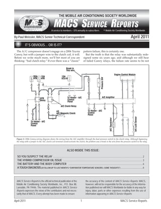
- 1. A service to members – $70 annually to subscribers © Mobile Air Conditioning Society Worldwide By Paul Weissler, MACS Senior Technical Correspondent April 2011 IT’S OBVIOUS… OR IS IT? The A/C compressor doesn’t engage on a 2006 Toyota pattern failure, this is certainly one. Camry, but with a jumper wire to the clutch coil, it will. But the truth is that the relay was substantially rede- Before we write much more, we’ll bet most of you are signed some six years ago, and although we still hear thinking: “bad clutch relay.” If ever there was a “classic” of failed Camry relays, the failure rate seems to be not Figure 1: 2006 Camry wiring diagram shows the wiring from the A/C amplifier through the dual pressure switch to the clutch relay. Although bypassing the relay with a jumper to the A/C clutch coil terminal would activate the clutch, the problem was a break in the wire from the pressure switch to the relay. ALSO INSIDE THIS ISSUE: SO YOU SUSPECT THE RELAY ..................................................................................................................................................... 2 THE HYBRID COMPRESSOR OIL ISSUE .................................................................................................................................... 3 THE BATTERY AND THE BODY COMPUTER ........................................................................................................................... 6 A TOUGH DIAGNOSIS (A FOLLOW-UP TO LAST MONTH’S “EVAPORATOR TEMPERATURE SENSORS—SOME THOUGHTS”) .........................................6 MACS Service Reports is the official technical publication of the the accuracy of the content of MACS Service Reports. MACS, Mobile Air Conditioning Society Worldwide, Inc., P.O. Box 88, however, will not be responsible for the accuracy of the informa- Lansdale, PA 19446. The material published in MACS Service tion published nor will MACS Worldwide be liable in any way for Reports expresses the views of the contributors and not neces- injury, labor, parts or other expenses resulting from the use of sarily that of MACS. Every attempt has been made to ensure information appearing in MACS Service Reports. April 2011 1 MACS Service Reports
- 2. much different from those of A/C clutch relays on any for body shops, like mobile technician and MACS Con- make. vention trainer John Anello, he’d probably say, “Collision The technician believed the pattern failure and re- damage is a major cause.” Technicians who work on a lot placed the relay, and by now you should not be surprised of very late models might say, “When add-on accessories to find that it didn’t fix the problem. are installed, the installers may yank on existing harness- Aha, you might be thinking (as some technicians did), es, damage existing terminals and bends pins in multi- it must be the amplifier (A/C module). Well, over the way connectors, tap into wires with Scotchloks and then years we’ve heard of amplifier failures, but considering maybe move them somewhere else, leaving damaged the rate at which Toyotas sell, the rate is not indicative wiring in their wake. And then there’s just the usual mis- of a significant pattern failure. So once more, the parts handling from technicians doing unrelated underhood replacement wouldn’t fix the problem. When it comes to service. But we’ll tell you this: for every new car with a relays, we have some additional thoughts, discussed in screw driven through a wire in a harness on the assembly the following article, “SO YOU SUSPECT THE RELAY.” line eventually causing a problem, there are probably a What was the problem? Answer: a broken wire be- few hundred problems from things that happen after the tween the relay and the dual pressure switch (Figure 1). car is put into service.■ Why do wires break? If you ask someone who does work SO YOU SUSPECT THE RELAY When the clutch doesn’t engage, or a fan doesn’t go to high speed, the relay is invariably one of the items on the list of suspects. If you have another relay on the shelf and it’s the correct one, you can do a fast substitution. But there are lots of different relays, and in general, too many parts that are likely to not be on the shelf. A better alternative is a new relay test kit recently in- troduced by Hickok-Waekon (www.hickok-inc.com, 800- 342-5080). The idea is neat and simple. The kit (Waekon No. 77465) contains four plug-in replacements for all common relay applications (Figure 2). One is a four- terminal replacement, but some of the five-terminals Figure 3: If the coil-side circuit of the relay is good, activating the ac- cessory should make the simulator body glow brightly. If the simulator body doesn’t glow, the circuit is defective, and if it glows dimly, there is resistance elsewhere in the circuit. check the secondary side circuit, using the kit’s remote test switch (which as shown in the photo of the kit, is a push button switch with wires). Plug the terminals of those wires into sockets in the relay simulator body, and Figure 2: This Waekon relay simulator kit makes it easy to test relays with the circuit activated, press the button on the switch, and the two circuits in which they are wired. It includes the four simula- which jumpers across the terminals of what would be the tors to replace different relays and a push-button test switch. secondary side of the relay (Figure 4). If the circuit now works, the relay was the problem and replacing it should also may work in place of a specific four-terminal. The be the fix. If it doesn’t, there’s a problem elsewhere in the replacement is sort-of a simulator. Install the appropri- circuit that includes the relay secondary, and a new relay ate one in place of a relay, activate the circuit, and if the would be a waste of time and money. circuit that includes the coil side of the relay is good, the There’s also a new type of relay test kit, recently intro- body of the relay simulator will glow brightly (Figure duced to the market by Lisle Corp., another well-known 3). If there’s high resistance somewhere in the circuit specialty tool/test equipment maker. In fact, there are (other than the relay), the body will glow dimly. If the two kits, each with four “jumpers.” Each jumper is a body doesn’t glow at all, there’s apparently a break in plug-in replacement for a specific type of relay, and the that circuit. removed relay is then plugged into the top of the jumper, If the simulator body glows brightly, the next step is to with which it forms a unit (Figure 5). The jumper has April 2011 2 MACS Service Reports
- 3. contact tabs for jumper wires or multimeter leads, corre- be reached with a jumper or meter lead. That permits sponding to the wiring connections of the relay that can’t easy testing for continuity and voltage at all terminals of the relay coil and contacts, so the technician can check for power at each, and jumper across with a conventional jumper wire to test the circuit operation. The primary kit, No. 56810, contains four relay jump- ers, a red one for 1984-96 Ford, a blue for later Fords and Chrysler products, a green for General Motors, Navistar truck and Kia, and a yellow for that common Bosch type used on most cars since the 1980’s. The second kit, No. 60610 (Figure 6), has an orange relay for GM and Navi- star, a white for Honda, Toyota, Nissan and 2009 Hyun- dai, an orange for certain GM and Navistar, and a purple for Nissan fuel pumps to 2004, and 2009 Hyundai. The purple may not be particularly useful, but the kit other- wise has important coverage. ■ Figure 4: If the relay simulator glows brightly, the next step is to check the secondary side circuit with the test switch with two wire leads, so it actually forms a type of jumper wire. Just plug each wire terminal into one of the special sockets in the relay simulator, then press the test switch button. If the circuit now works, the relay is defective. If it doesn’t, the problem is elsewhere in the circuit and a new relay won’t help. Figure 5: Lisle “jumper” replaces the relay in the fuse box cavity, and the relay itself plugs into the top of the jumper to complete the test setup. The Figure 6: This is one of the two kits of four Lisle “jumpers” that plug into jumper has accessible contact pads and tabs for circuit and relay testing the fuse box relay cavity. with jumper wires and a multimeter. THE HYBRID COMPRESSOR OIL ISSUE If you’re a regular MACS Service Report reader, you no oil contamination problem with the A/C, even if the know we’ve covered the subject of the effect of PAG A/C hadn’t been on. oil contamination of A/C systems with electric drive There are two things wrong with this theory, certainly compressors. We have explained that the on-board di- on Toyota systems like the Prius, which are the bulk of agnostics will check the ground isolation of the system the hybrid market with electric motor-drive compres- and log a diagnostic trouble code if the resistance is low sors at this time. First, the oil issue (assuming only par- – something like the ground fault interrupter switch in tial contamination and not a totally incorrect charge with many household circuits. One of the possible causes of PAG oil) that causes a trouble code to be logged, occurs that code is PAG oil in the system, instead of the specified only in the first seconds of A/C operation. If the CAN polyol ester (POE) oil, causing loss of resistivity in the (controller area network) data bus diagnostics detect the chambers of the compressor. low resistivity, it may log POAG-611, and this can disable However, there seems to be an impression that if the the A/C, but it does not prevent the vehicle itself from hybrid system turns on a ready light, all is okay, and if running. Neither Toyota nor DENSO, the manufacturer the car arrived at your shop without a warning , there is of the system, discloses the computer algorithm that sets April 2011 3 MACS Service Reports
- 4. that code. a CAN communication failure and an A/C failure from So if the A/C doesn’t run, the first thing to do is a trou- PAG oil contamination. ble code scan, and if that code comes up, check vehicle history for any A/C service, to determine if there’s any Compressor Motor Testing chance that the system was recharged and PAG oil added If you don’t know whether there is severe oil cross- instead of polyol ester oil (POE) -- ND-11 recommended contamination causing the motor to fail, a good way to by Toyota for the DENSO system. If you trace the prob- start is by checking the compressor motor for a short to lem to significant oil contamination (Honda says any ground. This is Toyota’s recommended procedure: contamination), you probably have heard that the manu- • Clear the trouble code(s) and turn the facturers say to replace all the components, and that is power switch (“ignition”) on. really, really expensive. • Set the blower speed to High, the Temper- However, you should be aware that in addition to ature to MAX COLD and the A/C on. contaminated oil, the code could be caused by other is- • After three minutes, turn the switch off sues, such as a defective electric motor in the compressor and remove the high-voltage safety plug or a communications problem in the CAN itself, and a from the battery box cover. scan tool with OE-level diagnostics also may produce a • Disconnect the two-wire connector from CAN communication trouble code. But if the only code is the high-voltage compressor and connect a POAG-611, a good vehicle history can give you the start- grounded ohmmeter to each of the two ter- ing point, and if POE oil contaminated by PAG is strongly minals on the motor. Each should read ultra- indicated, keep that in mind. But note that a basic check high resistance (2 megohm or greater). Note of the electric motor-drive is not difficult, and a defec- the wiring schematic, which shows the eight tive motor, which certainly could have been caused by oil wires that connect to the compressor. You contamination (if it occurred some time ago), is impor- want the two that go to the inverter. See Fig- tant to also keep in the diagnostic evaluation. ures 7 and 8. It is possible, although unlikely, for the A/C to log both • If the readings are low, this indicates a shorted motor. Replace the com- pressor assembly. If you get the acceptable readings (over 2 megohm resistance), try to oper- ate the A/C system but without a cooling load, this way: A/C Cycle Test • Reinstall the connector to the compressor motor and refit the high-voltage safety plug. • Clear any trouble codes and turn on the power switch (“ignition”). • Set blower speed to LOW, Temperature to 77 degrees F. and A/C (or defrost) on. • Run the A/C for 10 min- utes, which will collect a maxi- mum amount of oil in the com- pressor. • Turn the power switch off and let the system sit overnight. • Remove the high-voltage safety plug and repeat the test with the two-wire connector un- plugged from the high-voltage compressor (grounded ohmme- ter to each of the two terminals on the motor. • Once more you should get Figure 7: Wiring schematic for the electric-motor-drive compressor in a 2010 Toyota Prius. The an ultra-high resistance reading two-wire connector is for those at the bottom, which run to the inverter. April 2011 4 MACS Service Reports
- 5. lower the oil contamination ratio sufficiently for the sys- tem to function normally. What would be “significant oil contamination?” Toyota doesn’t say, but the Prius system takes only 3.5 oz. of oil because the compressor itself is designed with baffles to minimize oil circulation with the refrigerant, keeping most of it in the compressor, both to improve lubrication and reduce energy used by the compressor to circulate it. So “a couple of ounces” is not minor stuff. However, as noted, Toyota does allow for the possibility of eliminat- ing the problem without replacing all the parts, so you’re not way out in left field. If you try to clear the codes, but POAG-611 comes back and the system will not operate, use a recovery/recycle/ recharge machine. Then replace what oil you recover with pure ND-11 POE oil. Clear the code once more, and if the A/C is operative again, happy days. If you don’t remove any or enough oil with the R/R/R machine to clear the code, or perhaps you’d prefer an ap- proach that is more likely to remove a maximum amount of contaminated oil, you can proceed this way: Perform the A/C cycle test for 10 minutes to collect oil in the compressor, turn off the power switch and remove the high-voltage safety plug from the battery cover. Then remove and drain the compressor. As we’ve noted, the Prius electric-drive compressor is designed to trap a lot of oil, so it is possible you may be able to get much of it out Figure 8: Illustration of compressor shows location of the motor termi- this way. It probably won’t be a quick and easy drain, but nals. Each should produce ultra-high resistance with an ohmmeter test from the vehicle owner’s standpoint it beats replacing to ground. expensive parts. It is possible that the compressor won’t run (and the code to be cleared), but then, there still may (for this test, Toyota specifies 3 megohm or be enough oil collected in the compressor for a drain to greater). work. If you get significantly lower readings (be sure to check If you have a case of major oil contamination, an in- ohmmeter and connections to be sure), replace the com- operative system as a result and no fix from the previ- pressor. If however, you have evidence that a PAG oil has ous suggestions, we’re back to the possibility of flushing, been in the system, Toyota does recommend changing all which although not recommended by Toyota, is some- the components in the A/C system. thing the motorist may prefer as an alternative to replac- ing all the parts. Oil Contamination However, you’ll have to explain to the motorist that If you’re able to absolutely confirm that a Toyota elec- the flush also may not cure the problem, and remember, tric-drive compressor system was charged with PAG oil the cross-contamination limit specification is just 1% for (such as with a vehicle history), do you really want to DENSO systems used by Toyota, just 2% for the Mitsubi- replace all the components? Well, better to ask, does the shi compressors used by Ford. Although DENSO does vehicle owner want you to do that? Almost surely not, set that limit, we cannot tell you at what voltage indica- and so long as the owner fully understands—and accepts tion the code sets, or for that matter, if that relates to a the cost of the effort-- you do have the option of trying specific oil contamination level. The chances are there’s to remove as much oil as possible and recharge the sys- a test or maybe more than one that the computer makes tem using the correct (ND-11 or equivalent) POE oil. The and a voltage limit that it looks for. The number may worst that can happen is that the effort doesn’t succeed, include a deterioration factor for the insulation on the and then the vehicle’s owner can decide if he wants to electric drive compressor motor windings. Whatever the make the investment in new parts. exact algorithm, there’s probably is a giant safety factor Toyota does recognize that a small amount (undefined) for the possibility of a technician not using lineman’s in- of PAG oil may have been put into the system, causing sulated gloves touching the compressor the instant the the trouble code to log. So it suggests collecting the maxi- A/C is turned on. mum amount of oil in the compressor, then draining the Although refrigerant flushing removes oil, there pres- compressor and adding fresh ND-11 oil. This could well ently is no data on how effective it may be in removing April 2011 5 MACS Service Reports
- 6. enough contaminated oil to be successful. And a refrig- With all these facts in mind, you should carefully ex- erant flush is not some super-fast procedure, although plain the situation to the motorist, so he doesn’t expect much of it may be done automatically, without a techni- an assured positive result. And because the compressor is cian in attendance. A solvent flush is another alternative, designed to trap oil, we’d be inclined at this time to stop although it has been used primarily for removing debris with a compressor drain. All we can say at this point is and dirty oil. One system, Hecat, reports success for re- that if we get any data – lab tests or even in-depth case moving debris and dirty oil from condensers, evapora- histories of successful flushes (with refrigerant or sol- tors and hoses after a compressor failure. However, it vent), we’ll report them to MACS members. All that said, must be performed very precisely to both work and not there have been a few technicians’ online reports of flush- leave any more than the slightest residual trace of the sol- ing after replacement of a failed Prius compressor, but vent. And here again, there is no lab data for using a sol- no details and following the compressor replacement, no vent flush to correct a problem of PAG oil contamination long-time performance and durability data. ■ of a hybrid system. THE BATTERY AND THE BODY COMPUTER The once simple act of disconnecting the battery safe). can now cause all kinds of issues, including the loss But then, except for some safety systems and the of computer memory, the triggering of antitheft codes in the radio, the setting of data bus communications codes, etc. So if you don’t have a computer memory saver, you could face this problem. Then, what if you have one, but it plugs into the cigarette lighter (which typically is part of the dashboard), and you have to pull the dash for a job, such as a heater core or evapo- rator replacement? Outwardly, there seems to be not much choice for saving the radio and computer memories, if all you have is that simple computer memory saver. You cer- tainly do have to disconnect the battery – after get- ting the radio antitheft code from the motorist (if the antitheft is activated). And if it takes some doing on his/her part to locate the code, so be it. Otherwise, if you disconnect and the audio system and it locks up, you or the customer probably will have to go through the dealer to get a factory-programmed code to reset the system. Fortunately, many late-model GM cars just automatically sense the VIN, so if the audio system hasn’t been changed, it should reactivate. But never assume the car you’re working on will reinitial- ize. Check the owner’s manual if the motorist doesn’t know. If you just remove the dashboard without discon- necting the battery, surely the instrument cluster com- puter, and likely the body computer if part of the dash assembly, will continue to be powered until the ve- hicle electronics suddenly lose the ground provided through the dashboard. That loss of ground may cause an internal body computer spike that could blow ei- Figure 9: The computer memory saver is an essential special tool. But ther or both modules (and any others that might be when you’re working under the dash and may have it out and apart for a while, you need more than a saver with a 9-volt battery. And you grounded through the dash). Whereas if you first just certainly want some place other than the cigarette lighter socket to plug disconnect the battery, the entire car will lose power it in for power, if the socket is in the dashboard. This EZ-Red unit plugs (and all the computer modules will be electronically into the OBD II connector, and includes both a battery and a power cord for lengthy operation. April 2011 6 MACS Service Reports
- 7. odometer, which have capacitive back-up electrical ies, etc., but many of them just plug into the cigarette power, you’ll also have all sorts of trouble codes to lighter socket, the same way as the 9-volter. And how erase, possibly some module initialization issues, etc., often is the lighter socket not working, leaving you issues from loss of memory. with a problem just as you’re starting the job? The savers that connect somewhere else, such as directly Better Way To Retain Memory to the battery cables, and have some form of power Sure, you have that little computer memory saver backup are what you should have. And over the years that holds a 9-volt battery, and if all you’re doing is we’ve talked about a few. changing a battery or other quick job, and you use a A new saver from E-Z Red, the MS4000 (www.ezred. fresh 9-volter, it’s fine, eliminating the worry about com, 800-522-7947) is an alternative. It plugs into the loss of data (although recording the radio antitheft OBD II connector under the dash, so it saves all the code still is something very worthwhile doing). memory and presets (including the antitheft codes). It But when you’re doing something significant to has an internal five amp-hour battery and an external the air conditioning system, the job can take a day or charger, simple off-on switch, low-volt indicator that more. There are memory savers with lantern batter- comes on at 11.7 volts (Figure 9). ■ A TOUGH DIAGNOSIS (A FOLLOW-UP TO LAST MONTH’S “EVAPORATOR TEMPERATURE SENSORS—SOME THOUGHTS”) The 2003 Lincoln Town Car came in with a no-cooling pressure switch circuit. He went through the Ford pin- complaint. The technician jumpered the clutch relay and point diagnostics, but found nothing wrong. However, the system worked, so he replaced the relay. But that the system would repeatedly come on intermittently didn’t fix the problem and he noticed the compressor for a few seconds, then cut out. He replaced the high- was noisy and the high side readings were bouncing. So side pressure “switch” (a pressure transducer), but that he replaced the compressor (and accumulator), and al- didn’t help. though the pressure readings then were okay, there was He didn’t know where to go from there, because he obviously still a circuit problem that had to be resolved. saw no other possibility in the wiring diagram (Figure He ran a scan that produced enhanced Ford power- 10). He asked for help, and then someone who knew train trouble code P1462, which is for the A/C high-side something about the Town Car of that vintage, said it Figure 10: 2003 Lincoln Town Car diagram in factory website shows both evaporator sensor (circled, bottom) and low refrigerant charge protection switch (circled, upper center). However, the evaporator sensor and its connection to the Powertrain Control Module did not appear in an early wiring diagram that is used in an aftermarket service information system. Even this particular factory website diagram, however, does not show the high-side transducer. April 2011 7 MACS Service Reports
- 8. had been changed from 2002, to include an evaporator again at 250 psi to restore compressor operation). temperature sensor. The technician checked his wiring Although there are trouble codes for switch and sen- diagram, and it didn’t show this sensor, but the sensor sor failures, you basically have to go through all the was there in the evaporator, and replacing it fixed the diagrams and component listings to see what’s in the problem. system, and check everything out. What happened? The answer is that the wiring dia- That’s a lesson that’s tough to learn. All we can sug- gram in the aftermarket service information system gest is that when you have an apparently insoluble was an early factory diagram that was in error. The di- problem, certainly an electrical one, a visit to the fac- agram on the factory website (www.motorcraftservice. tory website might give you later information and com) was not perfect either. It shows the evap sensor corrected diagrams. We can remember when errone- and the low-pressure/low refrigerant cutout switch, ous wiring diagrams, with missing circuits, could but not the high side pressure transducer – you have take years to correct – if ever. These days, with online to go to another diagram to see that (Figure 11). information, the corrections get made, if the factory If you go back to the 2002 Town Car, the cycling was has enough people working to upgrade the website. controlled by the cycling clutch switch on the accu- We send in correction notices, but we have seen some mulator (closes at 28 psi, opens at 44.5 psi). The high- slow responses – one took over a year for the change pressure side has a cutout switch, not a transducer, to be made, and that was with a factory site. It’s a to signal the powertrain control module to break the tough business, so just accept the fact that an occa- clutch circuit if pressures reach 420 psi (switch closes sional struggle is par for the course. ■ Figure 11: It’s necessary to find this additional wiring diagram for the 2003 Lincoln Town Car to see the circuit that includes the high-side transducer (circled) and its wiring to the Powertrain Control Module. Editors: Elvis Hoffpauir, Paul DeGuiseppi MACS Service Reports is published monthly by the Mobile Air Conditioning Soci- Production Designer: Laina Casey ety Worldwide. It is distributed to members of MACS Worldwide and is intended Manager of Service Training: Paul DeGuiseppi for the educational use of members of the automotive air conditioning service and repair industry. Suggestions for articles will be considered for publication, Mobile Air Conditioning Society Worldwide however, MACS Worldwide reserves the right to choose and edit all submissions. P.O. Box 88, Lansdale, PA 19446 Nonmembers wishing to receive MACS Service Reports should contact the na- Phone: (215) 631-7020 • Fax: (215) 631-7017 tional office. Non-member price for 12 issues is $70. Email: membership@macsw.org • Website: www.macsw.org April 2011 8 MACS Service Reports
- 9. MACS Service Reports Quiz #MSR0311 Based on March 2011 issue of MACS Service Reports This test must be received within 30 days in order to be processed. Fill out the information at left, and circle the correct answer for each question in the box below. Mail or fax your completed test to: MACS Worldwide, P.O. Box 88, Lansdale, PA 19446; Fax: (215) 631-7017 Your Name: 1. When performing diagnostics, “sub- indication the system has successfully c. Both. stituting with a known good part” is gone into self-diagnostics is that the d. Neither. Company Name: understandable EXCEPT for when: digital display will flash three times in a. The part is a high-failure item. quick succession, then display two- 8. An airstream sensor, used instead Position/Title: b. There is an applicable service digit trouble codes (if any are present). of the conventional evaporator tem- Address: bulletin. Who is right? perature sensor, is located: c. The part is relatively inexpen- a. Technician A. a. In the plenum just before the City: sive. b. Technician B. evaporator core. d. The part is easy to replace. c. Both. b. In the plenum close to the State/Zip: d. Neither. evaporator outlet face. 2. On a 2001 Hyundai Santa Fe: c. In the air duct to the A/C cen- Day Phone: ( ) ter registers. a. The A/C system’s triple pres- 5. Technician A says the de-ice sure switch “low” and “high” con- switch is a form of evaporator temper- d. Either a or b is correct, Fax: tacts are wired in series. ature sensor intended to prevent evap- depending on system design. E-mail: b. The A/C system’s triple pres- orator icing. Technician B says that if sure switch “low” contacts close the switch sticks closed, the compres- 9. Technician A says the airstream Is this your first MSR Test? (Circle one) at pressures of about 30 psi and sor clutch probably will not engage. type evaporator temperature sensor YES NO under. Who is right? on General Motors Cadillac DTS and All members of MACS Worldwide may copy c. The A/C system’s triple pres- a. Technician A. Buick Lucerne is removed by taking sure switch “high” contacts close b. Technician B. out the HVAC case, taking it apart and and distribute copies of this test to their at pressures of about 385 psi c. Both. depressing sensor retaining tangs company employees. The MACS Service accessible on the inside. Technician B Reports Training Program is only available to and higher. d. Neither. d. All of the above. says that for replacement, a failed members of MACS and their company airstream type sensor on DTS and 6. Technician A says the evaporator employees. Lucerne must be detached from the 3. Technician A says if it detects a hard temperature sensor is used on sys- failure of the ambient temperature sen- tems with an expansion valve. harness with a special tool. Who is Certificate of Achievement - If you pass 8 tests sor, the A/C system on a 2001 Hyundai Technician B says the evaporator tem- right? each year (Aug. - Aug.), scoring at least 80% on Santa Fe inserts a fail-safe value of 25 perature sensor is never used with an a. Technician A. each test, you qualify for a certificate of achievement. degrees C (77 degrees F.). Technician orifice tube/accumulator system. Who b. Technician B. If you qualify, MACS Worldwide will notify you by mail B says if it detects a hard failure of the is right? c. Both. and you may order your Certificate of Achievement in-car temperature sensor, the A/C a. Technician A. d. Neither. for $10.00. system on a 2001 Hyundai Santa Fe b. Technician B. inserts a fail-safe value of 20 degrees c. Both. 10. A periodically-seen cause of inter- C (68 degrees F.). Who is right? d. Neither. mittent operation with some conven- a. Technician A. tional evaporator temperature sensors Rec'd: 1. A B C D is when the sensor: b. Technician B. 7. Technician A says that the evapo- 2. A B C D c. Both. rator temperature sensor should be a a. Must issue rapid changes in 3. A B C D d. Neither. tight fit between the fins. Technician B temperature detection. Score: 4. A B C D says sensor looseness, however, is an b. Sees no changes for an 5. A B C D 4. Technician A says to initiate ATC issue only if there is evaporator sur- extended period, and goes 6. A B C D system self diagnostics on a 2001 face corrosion, and the sensor should through a “drift” as a result. Hyundai Sana Fe, press the AMB not be relocated otherwise. Who is c. Is coated with moisture, as Init.: 7. A B C D (ambient) switch at least five times right? may happen with high humidity. 8. A B C D d. All of the above. 9. A B C D within two seconds while pressing the a. Technician A. 10. A B C D AUTO switch. Technician B says an b. Technician B.