SlideShare ist ein Scribd-Unternehmen logo
1 von 2
What is the difference between a DC motor and servo motor?
A DC motor has a two wire connection. All drive power is supplied over these two wires—think of a
light bulb. When you turn on a DC motor, it just starts spinning round and round. Most DC motors are
pretty fast, about 5000 RPM (revolutions per minute).
With the DC motor, its speed (or more accurately, its power level) is controlled using a technique
named pulse width modulation, or simply PWM. This is idea of controlling the motor’s power level by
strobing the power on and off. The key concept here is duty cycle—the percentage of “on time”
versus“off time.” If the power is on only 1/2 of the time, the motor runs with 1/2 the power of its full-
on operation.
If you switch the power on and off fast enough, then it just seems like the motor is running weaker—
there’s no stuttering. This is what PWM means when referring to DC motors. The Handy Board’s DC
motor power drive circuits simply switch on and off, and the motor runs more slowly because it’s only
receiving power for 25%, 50%, or some other fractional percentage of the time.
A servo motor is an entirely different story. The servo motor is actually an assembly of four things: a
normal DC motor, a gear reduction unit, a position-sensing device (usually a potentiometer—a volume
control knob), and a control circuit.
The function of the servo is to receive a control signal that represents a desired output position of the
servo shaft, and apply power to its DC motor until its shaft turns to that position. It uses the position-
sensing device to determine the rotational position of the shaft, so it knows which way the motor must
turn to move the shaft to the commanded position. The shaft typically does not rotate freely round and
round like a DC motor, but rather can only turn 200 degrees or so back and forth.
The servo has a 3 wire connection: power, ground, and control. The power source must be constantly
applied; the servo has its own drive electronics that draw current from the power lead to drive the
motor.
The control signal is pulse width modulated (PWM), but here the duration of the positive-going pulse
determines the position of the servo shaft. For instance, a 1.520 millisecond pulse is the center position
for a Futaba S148 servo. A longer pulse makes the servo turn to a clockwise-from-center position, and a
shorter pulse makes the servo turn to a counter-clockwise-from-center position.
The servo control pulse is repeated every 20 milliseconds. In essence, every 20 milliseconds you are
telling the servo, “go here.”
To recap, there are two important differences between the control pulse of the servo motor versus the
DC motor. First, on the servo motor, duty cycle (on-time vs. off-time) has no meaning whatsoever—all
that matters is the absolute duration of the positive-going pulse, which corresponds to a commanded
output position of the servo shaft. Second, the servo has its own power electronics, so very little power
flows over the control signal. All power is draw from its power lead, which must be simply hooked up
to a high-current source of 5 volts.
Contrast this to the DC motor. On the Handy Board, there are specific motor driver circuits for four DC
motors. Remember, a DC motor is like a light bulb; it has no electronics of its own and it requires a
large amount of drive current to be supplied to it. This is the function of the L293D chips on the Handy
Board, to act as large current switches for operating DC motors.
Plans and software drivers are given to operate two servo motors from the HB. This is done simply by
taking spare digital outputs, which are used to generate the precise timing waveform that the servo uses
as a control input. Very little current flows over these servo control signals, because the servo has its
own internal drive electronics for running its built-in motors.

Weitere ähnliche Inhalte

Mehr von Krunal Siddhapathak

Mehr von Krunal Siddhapathak (11)

Grid computing
Grid computingGrid computing
Grid computing
 
Microblaze
MicroblazeMicroblaze
Microblaze
 
MICROWAVE RADIO COVERAGE FOR VEHICLE TO-VEHICLE AND IN-VEHICLE COMMUNICATION
MICROWAVE RADIO COVERAGE FOR VEHICLE TO-VEHICLE AND IN-VEHICLE COMMUNICATION MICROWAVE RADIO COVERAGE FOR VEHICLE TO-VEHICLE AND IN-VEHICLE COMMUNICATION
MICROWAVE RADIO COVERAGE FOR VEHICLE TO-VEHICLE AND IN-VEHICLE COMMUNICATION
 
Optical coherence tomography
Optical coherence tomographyOptical coherence tomography
Optical coherence tomography
 
Sic a new era in power electronics
Sic a new era in power electronicsSic a new era in power electronics
Sic a new era in power electronics
 
Ultra wide band antenna
Ultra wide band antennaUltra wide band antenna
Ultra wide band antenna
 
Atumatic toll tax system
Atumatic toll tax systemAtumatic toll tax system
Atumatic toll tax system
 
Musketeers mind rover
Musketeers mind roverMusketeers mind rover
Musketeers mind rover
 
Larrabee
LarrabeeLarrabee
Larrabee
 
Embedded C
Embedded CEmbedded C
Embedded C
 
Features of modern intel microprocessors
Features of modern intel microprocessorsFeatures of modern intel microprocessors
Features of modern intel microprocessors
 

Difference between servo and dc

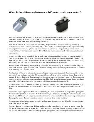
  • 1. What is the difference between a DC motor and servo motor? A DC motor has a two wire connection. All drive power is supplied over these two wires—think of a light bulb. When you turn on a DC motor, it just starts spinning round and round. Most DC motors are pretty fast, about 5000 RPM (revolutions per minute). With the DC motor, its speed (or more accurately, its power level) is controlled using a technique named pulse width modulation, or simply PWM. This is idea of controlling the motor’s power level by strobing the power on and off. The key concept here is duty cycle—the percentage of “on time” versus“off time.” If the power is on only 1/2 of the time, the motor runs with 1/2 the power of its full- on operation. If you switch the power on and off fast enough, then it just seems like the motor is running weaker— there’s no stuttering. This is what PWM means when referring to DC motors. The Handy Board’s DC motor power drive circuits simply switch on and off, and the motor runs more slowly because it’s only receiving power for 25%, 50%, or some other fractional percentage of the time. A servo motor is an entirely different story. The servo motor is actually an assembly of four things: a normal DC motor, a gear reduction unit, a position-sensing device (usually a potentiometer—a volume control knob), and a control circuit. The function of the servo is to receive a control signal that represents a desired output position of the servo shaft, and apply power to its DC motor until its shaft turns to that position. It uses the position- sensing device to determine the rotational position of the shaft, so it knows which way the motor must turn to move the shaft to the commanded position. The shaft typically does not rotate freely round and round like a DC motor, but rather can only turn 200 degrees or so back and forth. The servo has a 3 wire connection: power, ground, and control. The power source must be constantly applied; the servo has its own drive electronics that draw current from the power lead to drive the motor. The control signal is pulse width modulated (PWM), but here the duration of the positive-going pulse determines the position of the servo shaft. For instance, a 1.520 millisecond pulse is the center position for a Futaba S148 servo. A longer pulse makes the servo turn to a clockwise-from-center position, and a shorter pulse makes the servo turn to a counter-clockwise-from-center position. The servo control pulse is repeated every 20 milliseconds. In essence, every 20 milliseconds you are telling the servo, “go here.” To recap, there are two important differences between the control pulse of the servo motor versus the DC motor. First, on the servo motor, duty cycle (on-time vs. off-time) has no meaning whatsoever—all that matters is the absolute duration of the positive-going pulse, which corresponds to a commanded
  • 2. output position of the servo shaft. Second, the servo has its own power electronics, so very little power flows over the control signal. All power is draw from its power lead, which must be simply hooked up to a high-current source of 5 volts. Contrast this to the DC motor. On the Handy Board, there are specific motor driver circuits for four DC motors. Remember, a DC motor is like a light bulb; it has no electronics of its own and it requires a large amount of drive current to be supplied to it. This is the function of the L293D chips on the Handy Board, to act as large current switches for operating DC motors. Plans and software drivers are given to operate two servo motors from the HB. This is done simply by taking spare digital outputs, which are used to generate the precise timing waveform that the servo uses as a control input. Very little current flows over these servo control signals, because the servo has its own internal drive electronics for running its built-in motors.