MX960 Router Hardware Overview
•Als PPTX, PDF herunterladen•
10 gefällt mir•10,506 views

The MX960 is an Ethernet-optimized edge router that provides switching and routing capabilities of up to 1.32 terabits per second. It enables services like VPNs, broadband, and data center interconnection. The MX960 provides redundancy through redundant power supplies, fan trays, routing engines, and switch control boards. It can stack up to three routers in a single rack for high port density.

Empfohlen
Weitere ähnliche Inhalte
Was ist angesagt?
Was ist angesagt? (20)
Andere mochten auch
Andere mochten auch (20)
Ähnlich wie MX960 Router Hardware Overview
Ähnlich wie MX960 Router Hardware Overview (20)
Mehr von Kashif Latif
Mehr von Kashif Latif (17)
Kürzlich hochgeladen
Kürzlich hochgeladen (20)
MX960 Router Hardware Overview
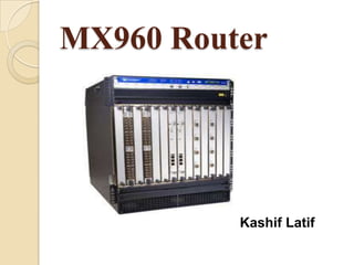
- 1. MX960 Router Kashif Latif
- 2. MX960 Router Overview The MX960 3D Universal Edge Router is an Ethernet-optimized edge router that provides both switching and carrier-class Ethernet routing. The MX960 router has a capacity of up to 1,320 gigabits per second (Gbps), full duplex.
- 3. Count… The MX960 router enables a wide range of business and residential applications and services, including high-speed transport and VPN services, next-generation broadband multiply services, and high-volume Internet data center internetworking. The MX960 chassis provides redundancy and resiliency. The hardware system is fully redundant, including power supplies, fan trays, Routing Engines, and Switch Control Boards.
- 4. Count… The MX960 router is 16 rack units (U) tall. Three routers can be stacked in a single floor-to-ceiling rack, for increased port density per unit of floor space. The router provides 14 slots that can be populated with up to 12 Dense Port Concentrators (DPCs) or Modular Port Concentrators (MPCs), six Flexible PIC Concentrators (FPCs), and two Switch Control Boards (SCBs) in nonredundant fabric configurations.
- 5. MX960 Hardware Components MX960 Chassis Description MX960 Rack-Mounting Hardware MX960 Midplane Description MX960 Dense Port Concentrator (DPC) MX960 Modular Port Concentrator (MPC) MX960 Modular Interface Card MX960 Switched Fabric (SF) MX960 Flexible PIC
- 6. Count… MX960 PIC MX960 Host Subsystem MX960 Switch Control Board (SCB) MX960 Routing Engine (RE) MX960 Craft Interface Description MX960 Power System Description MX960 Cooling System MX960 Cable Manager
- 7. MX960 Chassis Description The router chassis is a rigid sheet metal structure that houses all the other router. The chassis installs in many types of racks, including 800-mm deep (or larger) enclosed cabinets, standard19-in. equipment racks, or telco open- frame racks.
- 8. MX960 Rack-Mounting Hardware The rack-mounting hardware for the MX960 router includes: The large mounting shelf for mounting in four- post racks, cabinets, and open-frame racks. The small mounting shelf for front-mounting in a four-post rack or cabinet. Front-mounting flanges on the front of the chassis for front-mounting in a four-post rack or cabinet. Two center-mounting brackets attached to the center of the chassis for center-mounting in an open-frame rack. For an open-frame rack, center- mounting is preferable because of the more even distribution of weight.
- 9. MX960 Midplane Description The midplane is located toward the rear of the chassis and forms the rear of the card cage. The midplane performs the following major functions: Data Path—Data packets are transferred across the midplane between the line cards through the fabric ASICs on the SCBs. Power Distribution—The router power supplies connect to the midplane, which distributes power to all the router components. Signal Path—The midplane provides the signal path to the line cards, SCBs, Routing Engines, and other system components for monitoring and control of the system.
- 10. MX960 Dense Port Concentrator A Dense Port Concentrator (DPC) is optimized for Ethernet density. The DPC assembly combines packet forwarding and Ethernet interfaces on a single board, with either two or four 10-Gbps Packet Forwarding Engines.
- 11. Count… The router has 11 dedicated DPC slots. DPCs install vertically in the front of the router. The dedicated DPC slots are numbered 0 though 5, and 7 though11, left to right. An additional multifunction slot labeled2/6 supports either an SCB or a DPC. ADPC can be installed in any slot that supports DPCs. You can install any combination of DPC types in the router.
- 12. DPC Components Each DPC consists of the following components: DPC cover, which functions as a ground plane and a stiffener Fabric interfaces Two Giga bit Ethernet interfaces that allow control information, route information, and Statistics to be sent between the Routing Engine and the CPU on the DPCs Two interfaces from the SCBs that enable the DPCs to be powered on and controlled Physical DPC connectors Two or four Packet Forwarding Engines Mid plane connectors and power circuitry Process or sub system, which includes a1.2-GHz CPU, system controller, and1GB of SDRAM Online button—Takes the DPC online or offline when pressed LEDs on the DPC face plate.
- 13. MX960 Modular Port Concentrator Modular Port Concentrators (MPCs) provide packet forwarding services. The MPCs are inserted into a slot in a router. Modular Interface Cards (MICs) provide the physical interfaces and install into the MPCs. You can install up to two MICs of different media types on the same MPC as long as the MPC supports those MICs. The MX960 router supports up to 12 MPCs.
- 14. Count… When a slot is not occupied by an MPC or other line card, you must insert a blank DPC panel to fill the empty slot and ensure proper cooling of the system. MPCs are hot-removable and hot-insert able. When you install an MPC in an operating router, the Routing Engine downloads the MPC software, the MPC runs its diagnostics, and the Packet Forwarding Engines housed on the MPC are enabled. Forwarding on other MPCs continues uninterrupted during this process.
- 15. MPC Components Each MPC consists of the following components: MPC card carrier, which includes two MIC slots (excludes the fixed configuration MPC) Fabric interfaces Two Giga bit Ethernet interfaces that allow control information, route information, and statistics to be sent between the Routing Engine and the CPU on the MPCs Two interfaces from the SCBs that enable the MPCs to be powered on and controlled Physical MPC connectors Up to four Junos Trio chipsets, which perform control functions tailored to the MPC’s media type. Mid plane connector sand power circuitry Process or subsystem, which includes a1.5-GHz CPU, system controller, and1GB of SDRAM. Online button which takes the MPC online or offline when pressed OK/Fail LED on the MPC face plate.
- 16. MX960 Modular Interface Card Modular Interface Cards (MICs) install into Modular Port Concentrators (MPCs) and provide the physical connections to various network media types. MICs allow different physical interfaces to be supported on a single line card. MICs are hot-removable and hot-insertable. You can install up to two MICs in the slots in each MPC.
- 17. MX960 Switched Fabric (SF) Switched Fabric is a network topology where network nodes connect with each other via one or more network switches.
- 18. Count… Each PFE (Packet Forwarding Engines) is connected to all Fabric Planes. Diagram shows only two DPCs (FPCs) in the chassis. All other DPCs are also connected in same way. 4 Active Planes and 2 Spare Planes.
- 19. MX960 Flexible PIC Concentrator A Flexible PIC Concentrator (FPC) occupies two Dense Port Concentrator (DPC) slots on an MX Series router. The MX960 router has 11 dedicated DPCs lots and one multi functions lot that supports either a DPC, FPC, or Switch Control Board (SCB). The dedicated DPC slots are numbered 0 though 5, and 7 though 11, left to right. The multi functions lot is labeled 2/6. Up to six FPC scan be installed vertically in any two slots that support FPCs. The interface corresponds to the lowest numbered DPC slot for which the FPC is installed.
- 20. FPC Components Each FPC consists of the following components: FPC card carrier, which includes two PIC slots Up to two Packet Forwarding Engines, each consisting of one I-chip for Layer 3 processing and one Layer 2 network processor Mid plane connectors and power circuitry Process or subsystem (PMB), which includes a1.2- GHz CPU, system controller, 1GB of SDRAM, and two Giga bit Ethernet interfaces Two LEDs, located on the craft interface above the FPC, that display the status of the FPC and are labeled OK and FAIL FPC online/offline button, located on the craft interface above the FPC
- 21. MX960 PIC PICs provide the physical connection to various network media types, receiving incoming packets from the network and transmitting out going packets to the network. During this process, each PIC performs framing and line-speed signaling for its media type. Before transmitting out going data packets, the PICs encapsulate the packets received from the FPCs. Each PIC is equipped with an ASIC that performs control functions specific to the media type of that PIC. PICs are hot-removable and hot-insert able. Up to two PICs can be installed in the slots in each FPC. Up to six FPCs can be installed in an MX960 router. PICs used in an FPC2 have captive screws at their upper and lower corners. PICs used in a Type 3 FPC have an upper eject or handle and a lower captive screw.
- 22. MX960 Host Subsystem The host subsystem provides the routing and system management functions of the router. You can install one or two host subsystems on the router. Each host subsystem functions as a unit; the Routing Engine must be installed directly into the Switch Control Board.
- 23. MX960 Switch Control Board The Switch Control Board (SCB) provides the following functions: Powers on and powers off DPCs, FPCs, and MPCs Controls clocking, system resets, and booting Monitor sand controls system functions, including fan speed, board power status, PDM status and control, and the craft interface Provides inter connections to all the DPCs, FPCs, and MPCs with in the chassis through the switch fabrics integrated into the SCB
- 24. SCB Components Each SCB consists of the following components: Chassis management Ethernet switch I2C bus logic, used for low-level communication with each component Component redundancy circuitry Control Board/Routing Engine master ship mechanism Gigabit Ethernet switch that is connected to the embedded CPU complex on all components
- 25. Count… Switch fabric—Provides the switching functions for the DPCs, FPCs, and MPCs Control FPGA—Provides the Peripheral Component Interconnect (PCI) interface to the Routing Engine 1000Base-T Ethernet controller—Provides a 1- Gbps Ethernet link between the Routing Engines Ethernet switch—Provides 1-Gbps link speeds between the Routing Engine and the DPCs, FPCs, and MPCs Circuits for chassis management and control Power circuits for the Routing Engine and SCB LEDs—Provide status
- 26. MX960 Routing Engine If the host system is redundant, the backup Routing Engine is hot-removable and hot- insertable, but the master Routing Engine is hot- pluggable. A Routing Engine that is not redundant is hot- pluggable.
- 27. Supported Routing Engines The MX960 router supports the following Routing Engines: RE-S-1300-2048 supported for Junos OS Release 8.2 and later. RE-S-2000-4096 supported for Junos OS Release 8.2 and later. RE-S-1800x2 supported for Junos OS Release 10.4 and later. RE-S-1800x4 supported for Junos OS Release 10.4 and later.
- 28. Routing Engine Function The Routing Engine runs the Junos OS. Software processes that run on the Routing Engine maintain the routing tables, manage the routing protocols used on the router, control the router interfaces, control some chassis components, and provide the interface for system management and user access to the router.
- 29. Routing Engine Slots You can install one or two Routing Engines in the router. Each Routing Engine must be installed directly in to an SCB. A USB port on the Routing Engine accepts a USB memory device that allows you to load Junos OS. The Routing Engines install in to the front of the chassis in vertical slots directly into the SCBs labeled 0 and1.
- 30. Count… If two Routing Engines are installed, one functions as the master and the other acts as the backup. If the master Routing Engine fails or is removed and the backup is configured appropriately, the backup takes over as the master. On the MX960 router, a Routing Engine installed in SCB slot 2/6 receives no power and supplies no additional routing functions. If no SCB is installed in slot2/6, install a blank panel in the slot.
- 31. Routing Engine Interface Ports Three ports, located on the right side of the routing engine, connect the Routing Engine to one or more external devices on which system administrators can issue Junos OS command- line interface (CLI) commands to manage the router. The ports with the indicated labels function as follows: 1. AUX 2. CONSOLE 3. ETHERNET
- 32. Count… AUX—Connects the Routing Engine to a laptop, modem, or other auxiliary device through a serial cable with an RJ-45 connector. CONSOLE—Connects the Routing Engine to a system console through a serial cable with an RJ-45 connector. ERNEETHT—Connects the Routing Engine through an Ethernet connection to a management LAN (or any other device that plugs into an Ethernet connection) for out-of-band management. The port uses an auto sensing RJ-45 connector to support 10-Mbps or100 Mbps connections. Two small LEDs on the bottom of the port indicate the connection in use: the LED flashes yellow or green for a10-Mbps or100-Mbps connection, and the LED is light green when traffic is passing through the port.
- 33. Routing Engine Boot Sequence The router is shipped with the Junos OS preinstalled on the Routing Engine. There are three copies of software: 1. One copy on the CompactFlash card in the Routing Engine. 2. One copy on the hard disk in the Routing Engine. 3. One copy on a USB flash drive that can be inserted into the slot on the Routing Engine faceplate. The Routing Engine boots from the storage media in this order: the USB device (if present), then the CompactFlash card, then the hard disk, then the LAN. Normally, the router boots from the copy of the software on the CompactFlash card.
- 34. MX960 Craft Interface The craft interface allows you to view status and troubleshooting information at a glance and to perform many system control functions. It is hot-insert able and hot-removable. The craft interface is located on the front of the router above the upper fan tray and contains LEDs for the router components, the alarm relay contacts, and alarm cutoff button.
- 35. MX960 Power System The MX960 router uses either AC or DC power supplies. The MX960 router is configurable with three or four normal-capacity AC power supplies, up to four high-capacity DC power supplies, and up to four high-capacity AC power supplies. The power supplies connect to the midplane, which distributes the different output voltages produced by the power supplies to the router components, depending on their voltage requirements.
- 36. MX960 Cooling System The cooling system consists of the following components: 1. Upper front fan tray 2. Lower front fan tray 3. Front air filter The cooling system components work together to keep all router components within the acceptable temperature range.
- 37. MX960 Cable Manager The standard cable manager is a tray located below the line-card cage, which has a row of fourteen dividers for securing the cables for each Dense Port Concentrator (DPC), Modular Port Concentrator (MPC), Modular Interface Card (MIC), or PIC.
- 38. Installing an MX960 Router To install the MX960 router follow these steps: 1. Prepare your installation site 2. Review the safety guidelines 3. Unpack the router and verify the parts 4. Install the mounting hardware 5. Lift the router on to the rack. Because of the weight of the router, we recommend that you use a mechanical lift 6. Connect cables to the network and external devices 7. Connect the grounding cable 8. Connect the AC power cord or DC power cables 9. Power on the router 10. Perform the initial system configuration
- 39. Tools and Parts Required to Maintain the MX960 Router To maintain hardware components, you need the following tools and parts: 1. ESD grounding wrist strap 2. Flat-blade (–) screwdriver 3. Phillips (+) screwdriver, number 1 4. Phillips (+) screwdriver, number 2
- 40. Troubleshooting Resources for MX960 Routers These are the resources which are helpful on troubleshooting for MX960 routers: 1. Command-Line Interface 2. Chassis and Interface Alarm Messages 3. Alarm Relay Contacts 4. Craft Interface LEDs 5. Component LEDs 6. Networks Technical Assistance Center
- 41. MX960 Field-Replaceable Units Field-replaceable units (FRUs) are router components that can be replaced at the customer site. Replacing most FRUs requires minimal router downtime. The router uses the following types of FRUs: Hot-removable and hot-insert able FRUs—You can remove and replace these components without powering off the router or disrupting the routing functions. Hot-pluggable FRUs—You can remove and replace these components without powering off the router, but the routing functions of the system are interrupted when the component is removed.
- 42. Hot-Removable and Hot-Insert able FRUs 1. Air filter 2. Craft interface 3. Backup Switch Control Board (SCB) (if redundant) 4. Master Switch Control Board (SCB) (if nonstop active routing is configured) 5. Backup Routing Engine (if redundant) 6. Master Routing Engine (if nonstop active routing is configured) 7. Dense Port Concentrators (DPCs) 8. Flexible PIC Concentrators (FPCs) 9. Modular Port Concentrators (MPCs) 10. Modular Interface Cards (MICs) 11. PICs 12. AC and DC power supplies (if redundant) 13. Fan tray
- 43. Hot-Pluggable FRUs 1. Master Switch Control Board (SCB) (if nonstop active routing is not configured) 2. Master Routing Engine (if nonstop active routing is not configured) 3. Switch Control Board (SCB) (non redundant) 4. Routing Engine (non redundant)
- 44. General Safety Guidelines of Hardware Equipment The following guidelines help ensure your safety and protect the hardware equipment from damage. The list of guidelines might not address all potentially hazardous situations in your working environment, so be alert and exercise good judgment at all times. Make sure that only authorized service personnel perform other system services. Keep the area around the chassis clear and free from dust before, during, and after installation. Keep tools away from areas where people could trip over them while walking. Do not wear loose clothing or jewelry, such as rings, bracelets, or chains, which could become caught in the chassis. Wear safety glasses if you are working under any conditions that could be hazardous to your eyes. Do not perform any actions that create a potential hazard to people or make the equipment unsafe.
- 45. Count… Never attempt to lift an object that is too heavy for one person to handle. Never install or manipulate wiring during electrical storms. Never install electrical jacks in wet locations unless the jacks are specifically designed for wet environments. Operate the hardware equipment only when the chassis is properly grounded. Do not open or remove chassis covers or sheet metal parts. Do not push or force any objects through any opening in the chassis frame. Such an action could result in electrical shock or fire. Avoid spilling liquid onto the chassis or onto any hardware component. Such an action could cause electrical shock or damage the hardware equipment. Avoid touching uninsulated electrical wires or terminals that have not been disconnected from their power source. Such an action could cause electrical shock.
- 46. Tools and Parts Required to Remove Components from an MX960 Router To remove components from the router or the router from a rack, you need the following tools and parts: 1. 2.5-mm flat-blade (–) screwdriver, for detaching alarm relay terminal block 2. 7/16-in. (11 mm) nut driver 3. Blank panels to cover empty slots 4. Electrostatic bag or antistatic mat, for each component 5. Electrostatic discharge (ESD) grounding wrist strap 6. Flat-blade (–) screwdriver 7. Mechanical lift, if available 8. Phillips (+) screwdrivers, numbers 1 and 2 9. Rubber safety cap for fiber-optic interfaces or cable 10. Wire cutters
- 47. Kashif Latif